Aspire 3000 / 3500 / 5000 Service Guide
Page 7
...System Block Diagram (For Aspire 3000/5000 3 System Block Diagram (For Aspire 3500 4 Board Layout (For Aspire 3000/5000 5 Top View 5 Bottom View 6 Panel 8 Front view 8 Closed front view 9 Left view 9 Right view 10 Rear view 10 Bottom view 11 Indicators 12 Launch Keys 13 Using the keyboard 14 Lock keys and embedded... the Optical Disc Drive Module 51 Removing the Memory 51 Removing the LCD Module 53 Removing the Middle Cover 53 Removing the Keyboard 53 Removing the Fan, the CPU Thermal Module and the CPU 53 Removing the Wireless LAN Card 54 Removing the LCD Module...
...System Block Diagram (For Aspire 3000/5000 3 System Block Diagram (For Aspire 3500 4 Board Layout (For Aspire 3000/5000 5 Top View 5 Bottom View 6 Panel 8 Front view 8 Closed front view 9 Left view 9 Right view 10 Rear view 10 Bottom view 11 Indicators 12 Launch Keys 13 Using the keyboard 14 Lock keys and embedded... the Optical Disc Drive Module 51 Removing the Memory 51 Removing the LCD Module 53 Removing the Middle Cover 53 Removing the Keyboard 53 Removing the Fan, the CPU Thermal Module and the CPU 53 Removing the Wireless LAN Card 54 Removing the LCD Module...
Aspire 3000 / 3500 / 5000 Service Guide
Page 8
...Control Board 63 Chapter 4 Troubleshooting 66 System Check Procedures 67 External Diskette Drive Check 67 External CD-ROM Drive Check 67 Keyboard or Auxiliary Input Device Check 67 Memory check 68 Power System Check 68 Touchpad Check 70 Power-On Self-Test (POST...5 Jumper and Connector Locations 84 Top View 84 Bottom View 86 Cahpter 6 FRU (Field Replaceable Unit) List 88 Aspire 3000/5000 Exploded Diagram 89 Aspire 3000/3500/5000 Series 101 Appendix A Model Definition and Configuration 101 Appendix B Test Compatible Components 104 Microsoft Windows XP Environment Test 105...
...Control Board 63 Chapter 4 Troubleshooting 66 System Check Procedures 67 External Diskette Drive Check 67 External CD-ROM Drive Check 67 Keyboard or Auxiliary Input Device Check 67 Memory check 68 Power System Check 68 Touchpad Check 70 Power-On Self-Test (POST...5 Jumper and Connector Locations 84 Top View 84 Bottom View 86 Cahpter 6 FRU (Field Replaceable Unit) List 88 Aspire 3000/5000 Exploded Diagram 89 Aspire 3000/3500/5000 Series 101 Appendix A Model Definition and Configuration 101 Appendix B Test Compatible Components 104 Microsoft Windows XP Environment Test 105...

Aspire 3000 / 3500 / 5000 Service Guide
Page 11
Input devices T T T T 88-/89-key Acer FineTouchTM keyboard Touchpad with 4-way integrated scroll button Four easy-launch buttons Two front-panel buttons: wireless LED-button and Bluetooth® LED-button I/O interface T T T T T T T T Three USB 2.0 ... jack Headphones/speaker/line-out port Type II PC Card slot DC-in jack for AC adaptor Pleaes aware of these two items only for Aspire 3000/5000 case usage : Note 1: Integrated 3D AGP graphics with up to 128 MB of shared memory based on system configuration with 512MB system memory Note...
Input devices T T T T 88-/89-key Acer FineTouchTM keyboard Touchpad with 4-way integrated scroll button Four easy-launch buttons Two front-panel buttons: wireless LED-button and Bluetooth® LED-button I/O interface T T T T T T T T Three USB 2.0 ... jack Headphones/speaker/line-out port Type II PC Card slot DC-in jack for AC adaptor Pleaes aware of these two items only for Aspire 3000/5000 case usage : Note 1: Integrated 3D AGP graphics with up to 128 MB of shared memory based on system configuration with 512MB system memory Note...

Aspire 3000 / 3500 / 5000 Service Guide
Page 12
System Block Diagram (For Aspire 3000/5000) 8 7 HOST 200MHz ZCLK 133MHz CLK-GEN AGP 66MHz ICS 952801 PCI 33MHz D USB 48MHz REF 14.318MHz Page 2 3V_ALWAYS 5VPCU 3V_S5 3V/5V 1.8V_S5 3VSUS C ... 16 RJ-11 Page 16 B Int. Speaker A PROJECT : ZL5 Size Document Number BLOCK DIAGRAM Rev 3A Date: Wednesday, February 23, 2005 Sheet 1 of 26 6 5 4 3 2 1 Chapter 1 3 Keyboard 87-Key Page 21 Touch Pad 6-Button Page 21 Page 11,12,13 LPC EC NS PC97551 Page 20 AC97 Codec ALC203 Page 17 BIOS...
System Block Diagram (For Aspire 3000/5000) 8 7 HOST 200MHz ZCLK 133MHz CLK-GEN AGP 66MHz ICS 952801 PCI 33MHz D USB 48MHz REF 14.318MHz Page 2 3V_ALWAYS 5VPCU 3V_S5 3V/5V 1.8V_S5 3VSUS C ... 16 RJ-11 Page 16 B Int. Speaker A PROJECT : ZL5 Size Document Number BLOCK DIAGRAM Rev 3A Date: Wednesday, February 23, 2005 Sheet 1 of 26 6 5 4 3 2 1 Chapter 1 3 Keyboard 87-Key Page 21 Touch Pad 6-Button Page 21 Page 11,12,13 LPC EC NS PC97551 Page 20 AC97 Codec ALC203 Page 17 BIOS...
Aspire 3000 / 3500 / 5000 Service Guide
Page 17
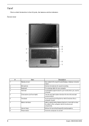
.... Front view # 1 2 3 4 5 6 7 8 9 Item Display screen Microphone Keyboard Palmrest Click buttons (Left and right) Touchpad Status indicators Launch keys Power button Description Also called LCD (Liquid Crystal Display), displays computer output. Internal microphone for launching frequently used programs. Turns the computer on and off . 8 Aspire 3000/3500//5000 Panel This is a brief introduction to...
.... Front view # 1 2 3 4 5 6 7 8 9 Item Display screen Microphone Keyboard Palmrest Click buttons (Left and right) Touchpad Status indicators Launch keys Power button Description Also called LCD (Liquid Crystal Display), displays computer output. Internal microphone for launching frequently used programs. Turns the computer on and off . 8 Aspire 3000/3500//5000 Panel This is a brief introduction to...
Aspire 3000 / 3500 / 5000 Service Guide
Page 21
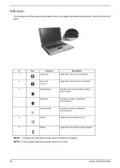
Wireless LAN Indicates the status of Bluetooth communication. Fully charged: light shows green when in AC mode. 12 Aspire 3000/3500//5000 Icon Function Description # Icon Function Description 1 Caps Lock Lights when Caps Lock is activated. 2 Num Lock Lights when Numeric Lock is activated... the battery is charging. NOTE: 2. NOTE: 1. Indicators The computer has three easy-to-read status icons on the upper-right above the keyboard, and four on . 5 Battery Lights when the battery is active. Bluetooth Indicates the status of Bluetooth communication. 4 Power Lights when the ...
Wireless LAN Indicates the status of Bluetooth communication. Fully charged: light shows green when in AC mode. 12 Aspire 3000/3500//5000 Icon Function Description # Icon Function Description 1 Caps Lock Lights when Caps Lock is activated. 2 Num Lock Lights when Numeric Lock is activated... the battery is charging. NOTE: 2. NOTE: 1. Indicators The computer has three easy-to-read status icons on the upper-right above the keyboard, and four on . 5 Battery Lights when the battery is active. Bluetooth Indicates the status of Bluetooth communication. 4 Power Lights when the ...
Aspire 3000 / 3500 / 5000 Service Guide
Page 22
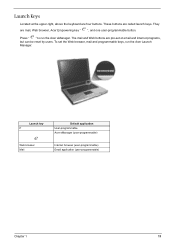
....eTbhberomwasilear,nmd aWileabnbdupttroongsraamremparbel-esekteoytse, mruanilthaendAicneter rLnaeutnpcrhograms, Manager. Hot Key Icon Function Description DFens-cFr1iption Launch Keys Fn-F2 Located at the upper-right, above the keyboard are mail, Web browser, Acer Empowering key " ", an"dAcoenr e user-programmable button. They are four buttons. These buttons are called launch keys.
....eTbhberomwasilear,nmd aWileabnbdupttroongsraamremparbel-esekteoytse, mruanilthaendAicneter rLnaeutnpcrhograms, Manager. Hot Key Icon Function Description DFens-cFr1iption Launch Keys Fn-F2 Located at the upper-right, above the keyboard are mail, Web browser, Acer Empowering key " ", an"dAcoenr e user-programmable button. They are four buttons. These buttons are called launch keys.
Aspire 3000 / 3500 / 5000 Service Guide
Page 23
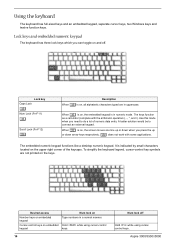
.... 14 Num lock off . Use this mode when you can toggle on the upper right corner of numeric data entry. To simplify the keyboard legend, cursor-control key symbols are in uppercase. The embedded numeric keypad functions like a desktop numeric keypad. When [ is indicated by small... Lock key Caps Lock @ Num Lock (Fn-F11) ] Scroll Lock (Fn-F12) [ Description When @is in a normal manner. Using the keyboard The keyboard has full-sized keys and an embedded keypad, separate cursor keys, two Windows keys and twelve function keys. Lock keys and embedded numeric keypad The...
.... 14 Num lock off . Use this mode when you can toggle on the upper right corner of numeric data entry. To simplify the keyboard legend, cursor-control key symbols are in uppercase. The embedded numeric keypad functions like a desktop numeric keypad. When [ is indicated by small... Lock key Caps Lock @ Num Lock (Fn-F11) ] Scroll Lock (Fn-F12) [ Description When @is in a normal manner. Using the keyboard The keyboard has full-sized keys and an embedded keypad, separate cursor keys, two Windows keys and twelve function keys. Lock keys and embedded numeric keypad The...

Aspire 3000 / 3500 / 5000 Service Guide
Page 24
it opens the application's context menu. Keys Windows logo key Application key Description Start button. Windows keys The keyboard has two keys that perform Windows-specific functions. Combinations with this key perform shortcut functions. Chapter 1 15 keypad. Hot Keys The computer employs hot keys...clicking the right mouse button; To activate hot keys, press and hold the key before pressing the other key in a normal manner. Desired access Main keyboard keys Num lock on Num lock off Hold while typing letters on embedded Type the letters in the hot key combination.
it opens the application's context menu. Keys Windows logo key Application key Description Start button. Windows keys The keyboard has two keys that perform Windows-specific functions. Combinations with this key perform shortcut functions. Chapter 1 15 keypad. Hot Keys The computer employs hot keys...clicking the right mouse button; To activate hot keys, press and hold the key before pressing the other key in a normal manner. Desired access Main keyboard keys Num lock on Num lock off Hold while typing letters on embedded Type the letters in the hot key combination.
Aspire 3000 / 3500 / 5000 Service Guide
Page 25
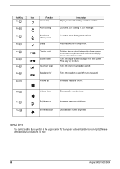
... Launches Power Management options. mutes the sound. To type: 16 Aspire 3000/3500//5000 Puts the computer in Acer eManager. Hot Key Fn-l Fn-m Fn-n Fn-o Fn-p Fn-q Fn-r Fn-s Fn-w Icon Function Hotkey help Acer eSetting Description Displays a list of your keyboard. Launches Acer eSetting in Sleep mode. Special keys You can locate the Euro...
... Launches Power Management options. mutes the sound. To type: 16 Aspire 3000/3500//5000 Puts the computer in Acer eManager. Hot Key Fn-l Fn-m Fn-n Fn-o Fn-p Fn-q Fn-r Fn-s Fn-w Icon Function Hotkey help Acer eSetting Description Displays a list of your keyboard. Launches Acer eSetting in Sleep mode. Special keys You can locate the Euro...
Aspire 3000 / 3500 / 5000 Service Guide
Page 26
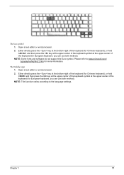
...Either directly press the key at the bottom-right of the keyboard (for Chinese keyboard), or hold and then press the key at the upper-center of the keyboard.symbol at the upper-center of the keyboard (for European keyboard, you can use both method). Either directly press the key ...at the bottom-right of the keyboard (for Chinese keyboard), or hold and then press the key at the upper-center of the keyboard.symbol at the upper-center of the keyboard (for European keyboard, you can use both method). Open a text editor or word ...
...Either directly press the key at the bottom-right of the keyboard (for Chinese keyboard), or hold and then press the key at the upper-center of the keyboard.symbol at the upper-center of the keyboard (for European keyboard, you can use both method). Either directly press the key ...at the bottom-right of the keyboard (for Chinese keyboard), or hold and then press the key at the upper-center of the keyboard.symbol at the upper-center of the keyboard (for European keyboard, you can use both method). Open a text editor or word ...
Aspire 3000 / 3500 / 5000 Service Guide
Page 29
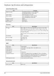
Aspire 5000 V1.00; Hardware Specifications and Configurations System Board Major Chip Item System core logic Audio controller Video controller Keyboard controller CardBus Controller IEEE Controller Processor CPU type Item CPU package CPU core voltage CPU I/O voltage BIOS Item BIOS vendor BIOS Version BIOS ROM type ...
Aspire 5000 V1.00; Hardware Specifications and Configurations System Board Major Chip Item System core logic Audio controller Video controller Keyboard controller CardBus Controller IEEE Controller Processor CPU type Item CPU package CPU core voltage CPU I/O voltage BIOS Item BIOS vendor BIOS Version BIOS ROM type ...

Aspire 3000 / 3500 / 5000 Service Guide
Page 36
... Total number of keypads Windows keys Internal & external keyboard work simultaneously Specification EC NS PC97551 keyboard controller Darfon 88-/89-key Yes Yes Battery Item Vendor & model name Battery Type Pack capacity Nominal voltage Number of battery cell Package configuration Package ...
... Total number of keypads Windows keys Internal & external keyboard work simultaneously Specification EC NS PC97551 keyboard controller Darfon 88-/89-key Yes Yes Battery Item Vendor & model name Battery Type Pack capacity Nominal voltage Number of battery cell Package configuration Package ...
Aspire 3000 / 3500 / 5000 Service Guide
Page 38
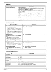
Display Standby Mode Keyboard, built-in standby mode. (spindle turned-off T Hard disk drive is idle within a specified period of FCC part 15, Subpart B for a specified period. Hard Disk ...
Display Standby Mode Keyboard, built-in standby mode. (spindle turned-off T Hard disk drive is idle within a specified period of FCC part 15, Subpart B for a specified period. Hard Disk ...
Aspire 3000 / 3500 / 5000 Service Guide
Page 39
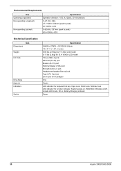
... Microphone/line-in jack Headphones/speaker/line-out jack Type II PC Card slot DC-in jack for AC adaptor One Plastic LED indicator for keyboard hot key: Caps Lock, Scroll Lock, NUmber lock LED indicator for function indicator: System power-on, HDD/ODD, Wireless on/off, Arcade LED mode, DC...
... Microphone/line-in jack Headphones/speaker/line-out jack Type II PC Card slot DC-in jack for AC adaptor One Plastic LED indicator for keyboard hot key: Caps Lock, Scroll Lock, NUmber lock LED indicator for function indicator: System power-on, HDD/ODD, Wireless on/off, Arcade LED mode, DC...

Aspire 3000 / 3500 / 5000 Service Guide
Page 57
...flowchart on the succeeding page gives you a graphic representation on the entire disassembly sequence and instructs you must first remove the keyboard, then disassemble the inside assembly frame in that need to remove the main board, you on the components that order. For... be removed during servicing. Start Battery HDD Module *2 HDD HDD Holder *2 Dimm Cover Memory *1 Modem Cover *2 Modem Board Hinge Caps *2 Middle Cover Keyboard *6 LCD Module *2 Launch Board Lower Case Assembly *2 FDD Module *3 *3 *11 *4 RTC Battery *3 Mini PCI Card Plate Upper Case Assembly Disconnect...
...flowchart on the succeeding page gives you a graphic representation on the entire disassembly sequence and instructs you must first remove the keyboard, then disassemble the inside assembly frame in that need to remove the main board, you on the components that order. For... be removed during servicing. Start Battery HDD Module *2 HDD HDD Holder *2 Dimm Cover Memory *1 Modem Cover *2 Modem Board Hinge Caps *2 Middle Cover Keyboard *6 LCD Module *2 Launch Board Lower Case Assembly *2 FDD Module *3 *3 *11 *4 RTC Battery *3 Mini PCI Card Plate Upper Case Assembly Disconnect...

Aspire 3000 / 3500 / 5000 Service Guide
Page 62
... as image shows. 3. Detach the middle cover carefully then remove it. See "Removing the Middle Cover" on page 53. 4. See "Removing the Keyboard" on page 53. 3. Then detach the fan from the main unit. 53 Chapter 3 See "Removing the Battery" on page 50. 2. Removing the Fan, the CPU ...Thermal Module and the CPU 1. Disconnect the fan cable. 6. Open the notebook as shown. 5. Remove the four screws securing the keyboard. 4. Removing the LCD Module Removing the Middle Cover 1. See "Removing the Battery" on page 50. 2.
... as image shows. 3. Detach the middle cover carefully then remove it. See "Removing the Middle Cover" on page 53. 4. See "Removing the Keyboard" on page 53. 3. Then detach the fan from the main unit. 53 Chapter 3 See "Removing the Battery" on page 50. 2. Removing the Fan, the CPU ...Thermal Module and the CPU 1. Disconnect the fan cable. 6. Open the notebook as shown. 5. Remove the four screws securing the keyboard. 4. Removing the LCD Module Removing the Middle Cover 1. See "Removing the Battery" on page 50. 2.
Aspire 3000 / 3500 / 5000 Service Guide
Page 64
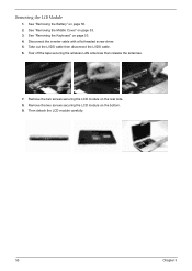
See "Removing the Keyboard" on page 50. 2. Take out the LVDS cable then disconnect the LVDS cable. 6. See "Removing the Battery" on page 53. 4. Remove the two screws securing the LCD module on the bottom. 9. Removing the LCD Module 1. Disconnect the inverter cable with a flat headed screw driver. 5. Tear off the tape securing the wireless LAN antennae then release the antennae. 7. Remove the two screws securing the LCD module on the rear side. 8. Then detach the LCD module carefully. 55 Chapter 3 See "Removing the Middle Cover" on page 53. 3.
See "Removing the Keyboard" on page 50. 2. Take out the LVDS cable then disconnect the LVDS cable. 6. See "Removing the Battery" on page 53. 4. Remove the two screws securing the LCD module on the bottom. 9. Removing the LCD Module 1. Disconnect the inverter cable with a flat headed screw driver. 5. Tear off the tape securing the wireless LAN antennae then release the antennae. 7. Remove the two screws securing the LCD module on the rear side. 8. Then detach the LCD module carefully. 55 Chapter 3 See "Removing the Middle Cover" on page 53. 3.

Aspire 3000 / 3500 / 5000 Service Guide
Page 65
... See "Removing the Middle Cover" on page 53. 4. Discnnect the LCD inverter board. 14. Disassembling the LCD Module Removing the LCD Bezel 1. See "Removing the Keyboard" on page 53. 3. Remove the four screws securing the left LCD bracket, then remove the left bracket.
... See "Removing the Middle Cover" on page 53. 4. Discnnect the LCD inverter board. 14. Disassembling the LCD Module Removing the LCD Bezel 1. See "Removing the Keyboard" on page 53. 3. Remove the four screws securing the left LCD bracket, then remove the left bracket.
Aspire 3000 / 3500 / 5000 Service Guide
Page 68
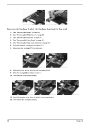
... Middle Cover" on page 58. 6. See "Removing the Upper Case Assembly" on page 53. 3. Remove the four screws securing the touchpad bracket. 9. See "Removing the Keyboard" on page 50. 2. Disconnect the touchpad FFC the remove it. 8. Pull back the tape covering the touchpad FFC. 7. Removing the Touchpad Bracket, the Touchpad Board...
... Middle Cover" on page 58. 6. See "Removing the Upper Case Assembly" on page 53. 3. Remove the four screws securing the touchpad bracket. 9. See "Removing the Keyboard" on page 50. 2. Disconnect the touchpad FFC the remove it. 8. Pull back the tape covering the touchpad FFC. 7. Removing the Touchpad Bracket, the Touchpad Board...


