
Aspire 1360 - 1520 Service Guide
Page 7
... Introduction 1 Features 1 System Block Diagram 3 Board Layout 4 Top View 4 Bottom View 5 Panel 6 Front View 6 Left view 7 Right View 8 Rear Panel 9 Bottom View 10 Indicators 11 Keyboard 12 Special keys 12 Hot Keys 15 Hardware Specifications and Configurations 18 Chapter 2 System Utilities 32 BIOS Setup Utility 32 Navigating the BIOS Utility 33... LCD 58 Removing the LCD Brackets 59 Removing the LCD Coaxial Cable 59 Removing the LCD Hinges 60 Disassembling the Main Unit 61 Removing the Keyboard 61 Removing the RTC Battery 61 VII
... Introduction 1 Features 1 System Block Diagram 3 Board Layout 4 Top View 4 Bottom View 5 Panel 6 Front View 6 Left view 7 Right View 8 Rear Panel 9 Bottom View 10 Indicators 11 Keyboard 12 Special keys 12 Hot Keys 15 Hardware Specifications and Configurations 18 Chapter 2 System Utilities 32 BIOS Setup Utility 32 Navigating the BIOS Utility 33... LCD 58 Removing the LCD Brackets 59 Removing the LCD Coaxial Cable 59 Removing the LCD Hinges 60 Disassembling the Main Unit 61 Removing the Keyboard 61 Removing the RTC Battery 61 VII

Aspire 1360 - 1520 Service Guide
Page 8
...to Wireless Unit 71 Chapter 4 Troubleshooting 72 System Check Procedures 73 External Diskette Drive Check 73 External CD-ROM Drive Check 73 Keyboard or Auxiliary Input Device Check 73 Memory check 74 Power System Check 74 Touchpad Check 76 Power-On Self-Test (POST) ... Recovery 93 Chapter 5 Jumper and Connector Locations 98 Top View 98 Bottom View 99 Chapter 6 FRU (Field Replaceable Unit) List 100 Aspire 1660 Exploded Diagram 101 Appendix A Model Definition and Configuration 112 Model Name Definition 112 Appendix B Test Compatible Components 114 Microsoft Windows XP...
...to Wireless Unit 71 Chapter 4 Troubleshooting 72 System Check Procedures 73 External Diskette Drive Check 73 External CD-ROM Drive Check 73 Keyboard or Auxiliary Input Device Check 73 Memory check 74 Power System Check 74 Touchpad Check 76 Power-On Self-Test (POST) ... Recovery 93 Chapter 5 Jumper and Connector Locations 98 Top View 98 Bottom View 99 Chapter 6 FRU (Field Replaceable Unit) List 100 Aspire 1660 Exploded Diagram 101 Appendix A Model Definition and Configuration 112 Model Name Definition 112 Appendix B Test Compatible Components 114 Microsoft Windows XP...

Aspire 1360 - 1520 Service Guide
Page 11
... two Type II CardBus PC Card slots Upgradeable hard disk and memory modules Human-centric design T Rugged, yet extremely portable, construction T Stylish appearance T Full-size keyboard with four programmable launch keys T Comfortable palm rest area with well-positioned touchpad I/O Ports T T T T T T T T T T T T Two Type II or one Type III PC CardBus (PCMCIA) slot...
... two Type II CardBus PC Card slots Upgradeable hard disk and memory modules Human-centric design T Rugged, yet extremely portable, construction T Stylish appearance T Full-size keyboard with four programmable launch keys T Comfortable palm rest area with well-positioned touchpad I/O Ports T T T T T T T T T T T T Two Type II or one Type III PC CardBus (PCMCIA) slot...

Aspire 1360 - 1520 Service Guide
Page 13
... Socket 16 North Bridge 17 Fan Connector 18 Note: There is no 18 on this main board. 19 Touchpad Cable Connector 20 HDD Connector 21 Keyboard Connector 22 Speaker Cable Connector 23 Optical Drive Connector 24 South Bridge 25 RTC Battery Connector 26 Launch Board Cable Connector 27 SW1 (Please see...
... Socket 16 North Bridge 17 Fan Connector 18 Note: There is no 18 on this main board. 19 Touchpad Cable Connector 20 HDD Connector 21 Keyboard Connector 22 Speaker Cable Connector 23 Optical Drive Connector 24 South Bridge 25 RTC Battery Connector 26 Launch Board Cable Connector 27 SW1 (Please see...

Aspire 1360 - 1520 Service Guide
Page 15
..., even after the prolonged use the computer. Front View # 1 2 3 4 5 6 7 8 9 Item Display screen Status indicators Power button Launch Keys Palmrest Click buttons & 4-way scroll key Touchpad Keyboard Ventilation Slot Description Liquid-Crystal Display (LCD) provides visual output. The left and right mouse buttons, the center button serves as you use . 6 Chapter 1 Panel...
..., even after the prolonged use the computer. Front View # 1 2 3 4 5 6 7 8 9 Item Display screen Status indicators Power button Launch Keys Palmrest Click buttons & 4-way scroll key Touchpad Keyboard Ventilation Slot Description Liquid-Crystal Display (LCD) provides visual output. The left and right mouse buttons, the center button serves as you use . 6 Chapter 1 Panel...
Aspire 1360 - 1520 Service Guide
Page 21
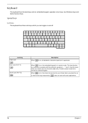
...with the arithmetic operators ), -, *, and /). When ] is on and off. A better solution would be to do a lot of numeric data entry. Keyboard The keyboard has full-sized keys and an embedded keypad, separate cursor keys, two Windows keys and twelve function keys. The keys function as a calculator (complete with... some applications. 12 Chapter 1 Special keys Lock keys The keyboard has three lock keys which you can toggle on , the screen moves one line up or down when you need to connect an external...
...with the arithmetic operators ), -, *, and /). When ] is on and off. A better solution would be to do a lot of numeric data entry. Keyboard The keyboard has full-sized keys and an embedded keypad, separate cursor keys, two Windows keys and twelve function keys. The keys function as a calculator (complete with... some applications. 12 Chapter 1 Special keys Lock keys The keyboard has three lock keys which you can toggle on , the screen moves one line up or down when you need to connect an external...
Aspire 1360 - 1520 Service Guide
Page 22
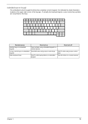
... keypad The embedded numeric keypad functions like a desktop numeric keypad. keypad. Desired access Number keys on embedded keypad Cursor-control keys on embedded keypad Main keyboard keys Num lock on the keys. Hold Shift while using cursor-control keys. Hold Fn while typing letters on the upper right corner of the...
... keypad The embedded numeric keypad functions like a desktop numeric keypad. keypad. Desired access Number keys on embedded keypad Cursor-control keys on embedded keypad Main keyboard keys Num lock on the keys. Hold Shift while using cursor-control keys. Hold Fn while typing letters on the upper right corner of the...

Aspire 1360 - 1520 Service Guide
Page 23
dialog box) Opens a context menu (same as a right-click). 14 Chapter 1 Combinations with this key perform shortcut functions. Below are a few examples: + Tab (Activates next taskbar button) + E (Explores My Computer) + F (Finds Document) + M (Minimizes All) j+ + M (Undoes Minimize All) + R (Displays the Run... Windows keys The keyboard has two keys that perform Windows-specific functions. Keys Windows logo key Application key Description Start button.
dialog box) Opens a context menu (same as a right-click). 14 Chapter 1 Combinations with this key perform shortcut functions. Below are a few examples: + Tab (Activates next taskbar button) + E (Explores My Computer) + F (Finds Document) + M (Minimizes All) j+ + M (Undoes Minimize All) + R (Displays the Run... Windows keys The keyboard has two keys that perform Windows-specific functions. Keys Windows logo key Application key Description Start button.

Aspire 1360 - 1520 Service Guide
Page 25
..., Control Panel. 2. then select United States-International and click on ADD; Open a text editor or word processor. 3. The Euro symbol If your keyboard layout is set up Windows. If not, select and click on OK. 5. Home Functions as the d key. Fn-} End Functions as the ...OK. To type the Euro symbol: 1. Verify that the keyboard layout used for US keyboard users: The keyboard layout is set to United States-international. Locate the Euro symbol on your keyboard. 2. For the Euro symbol to work, the keyboard layout has to United States-International. NOTE: for "En...
..., Control Panel. 2. then select United States-International and click on ADD; Open a text editor or word processor. 3. The Euro symbol If your keyboard layout is set up Windows. If not, select and click on OK. 5. Home Functions as the d key. Fn-} End Functions as the ...OK. To type the Euro symbol: 1. Verify that the keyboard layout used for US keyboard users: The keyboard layout is set to United States-international. Locate the Euro symbol on your keyboard. 2. For the Euro symbol to work, the keyboard layout has to United States-International. NOTE: for "En...

Aspire 1360 - 1520 Service Guide
Page 26
... and Wireless buttons. To set by the user. Launch Keys Located at the top of the keyboard are six buttons. The Wireless and Bluetooth buttons cannot be set the other four launch keys, run the Acer Launch Manager. # 1 2 3 4 5 6 Icon Mail Function Web browser e P Bluetooth (optional) Description Launches email application Launches Internet browser...
... and Wireless buttons. To set by the user. Launch Keys Located at the top of the keyboard are six buttons. The Wireless and Bluetooth buttons cannot be set the other four launch keys, run the Acer Launch Manager. # 1 2 3 4 5 6 Icon Mail Function Web browser e P Bluetooth (optional) Description Launches email application Launches Internet browser...
Aspire 1360 - 1520 Service Guide
Page 27
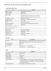
... AMD Sempron processor 2600+ to 3000+ or higher (for Aspire 1360) AMD Athlon 64 processor 3000+ to 3400+ or higher (for Aspire 1520) uOG 754 pin 1.5V High speed: 1.2V => for RAM 2.5V Low speed: 1.2V =>for Aspire 1520 Series Embedded in VT8235CE Mitsubish LPC keyboard controller M38857 TI PCI 7420 Embedded in VT8235CE TI PCI...
... AMD Sempron processor 2600+ to 3000+ or higher (for Aspire 1360) AMD Athlon 64 processor 3000+ to 3400+ or higher (for Aspire 1520) uOG 754 pin 1.5V High speed: 1.2V => for RAM 2.5V Low speed: 1.2V =>for Aspire 1520 Series Embedded in VT8235CE Mitsubish LPC keyboard controller M38857 TI PCI 7420 Embedded in VT8235CE TI PCI...

Aspire 1360 - 1520 Service Guide
Page 38
... and system is not ready to enter Hibernation mode. 2.System standby/ Hibernation timer expires and system is ready to enter Hibernation mode. Display Standby Mode Keyboard, built-in standby mode. (spindle turned-off T Hard disk drive is idle within a specified period of time. Hibernation Mode Enter Hibernation Mode (suspend to HDD...
... and system is not ready to enter Hibernation mode. 2.System standby/ Hibernation timer expires and system is ready to enter Hibernation mode. Display Standby Mode Keyboard, built-in standby mode. (spindle turned-off T Hard disk drive is idle within a specified period of time. Hibernation Mode Enter Hibernation Mode (suspend to HDD...
Aspire 1360 - 1520 Service Guide
Page 43
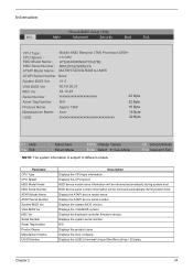
Info. Displays the keyboard controller firmware version. N/A Displays the product name. Displays the Acer company. Display the ATAPI device serial number Displays the system BIOS version. Display the ATAPI device model name. Displays the CPU speed. Displays ... BIOS Ver KBC Ver Serial Number 90.F8.00.37 02.13.29 xxxxxxxxxxxxxxxxxxxxxx 22 Byte Asset Tag Number N/A 32 Byte Produce Name Aspire 1360 16 Byte Manufacturer Name: Acer UUID: xxxxxxxxxxxxxxxxxxxxxxxxxxxxxxxx 16 Byte 32 Byte F1 Help Esc Exit ↑ ↓ Select Item ← → Select Menu F5/F6...
Info. Displays the keyboard controller firmware version. N/A Displays the product name. Displays the Acer company. Display the ATAPI device serial number Displays the system BIOS version. Display the ATAPI device model name. Displays the CPU speed. Displays ... BIOS Ver KBC Ver Serial Number 90.F8.00.37 02.13.29 xxxxxxxxxxxxxxxxxxxxxx 22 Byte Asset Tag Number N/A 32 Byte Produce Name Aspire 1360 16 Byte Manufacturer Name: Acer UUID: xxxxxxxxxxxxxxxxxxxxxxxxxxxxxxxx 16 Byte 32 Byte F1 Help Esc Exit ↑ ↓ Select Item ← → Select Menu F5/F6...

Aspire 1360 - 1520 Service Guide
Page 57
Start Battery HDD Module G*2 HDD HDD Holder *2 DIMM Cover Memory *2 Modem Cover Hinge Caps Wireless LAN Board D*2 Modem Board J*2 Middle Cover RTC Battery Keyboard F*6 LCD Module *2 Launch Board Second Fan J*3 Bracket Lower Case Assembly J*2 FDD Module J*5 F*10 D*4 Upper Case Assembly D*4 Wireless LAN Antenna Touchpad... succeeding page gives you a graphic representation on the entire disassembly sequence and instructs you must first remove the keyboard, then disassemble the inside assembly frame in that need to remove the main board, you on the components that order.
Start Battery HDD Module G*2 HDD HDD Holder *2 DIMM Cover Memory *2 Modem Cover Hinge Caps Wireless LAN Board D*2 Modem Board J*2 Middle Cover RTC Battery Keyboard F*6 LCD Module *2 Launch Board Second Fan J*3 Bracket Lower Case Assembly J*2 FDD Module J*5 F*10 D*4 Upper Case Assembly D*4 Wireless LAN Antenna Touchpad... succeeding page gives you a graphic representation on the entire disassembly sequence and instructs you must first remove the keyboard, then disassemble the inside assembly frame in that need to remove the main board, you on the components that order.

Aspire 1360 - 1520 Service Guide
Page 70
... See "Removing the Middle Cover" on page 54. 3. Use a plastic tweezers or a plastic flat screwdriver to disconnect the keyboard cable from the main board carefully, then remove the keyboard. See "Removing the Battery" on page 50. 2. See "Removing the Battery" on page 50. 2. Disconnect the RTC ...battery cable then remove it . 61 Chapter 3 See "Removing the Middle Cover" on page 61. 4. See "Removing the Keyboard" on page 54. 3. To remove the keyboard, carefully pull the keyboard out and upwards as the pticute shows. 4. Disassembling the Main Unit Removing the...
... See "Removing the Middle Cover" on page 54. 3. Use a plastic tweezers or a plastic flat screwdriver to disconnect the keyboard cable from the main board carefully, then remove the keyboard. See "Removing the Battery" on page 50. 2. See "Removing the Battery" on page 50. 2. Disconnect the RTC ...battery cable then remove it . 61 Chapter 3 See "Removing the Middle Cover" on page 61. 4. See "Removing the Keyboard" on page 54. 3. To remove the keyboard, carefully pull the keyboard out and upwards as the pticute shows. 4. Disassembling the Main Unit Removing the...

Aspire 1360 - 1520 Service Guide
Page 71
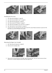
.... 2. See "Removing the Battery" on page 50. 2. Chapter 3 62 See "Removing the Middle Cover" on page 61. 4. See "Removing the Keyboard" on page 54. 3. Removing the Processor 1. See "Removing the Keyboard" on page 61. 5. See "Removing the RTC Battery" on page 61. 4. Removing the Thermal Module 1. Then remove the thermal module. Then...
.... 2. See "Removing the Battery" on page 50. 2. Chapter 3 62 See "Removing the Middle Cover" on page 61. 4. See "Removing the Keyboard" on page 54. 3. Removing the Processor 1. See "Removing the Keyboard" on page 61. 5. See "Removing the RTC Battery" on page 61. 4. Removing the Thermal Module 1. Then remove the thermal module. Then...
Aspire 1360 - 1520 Service Guide
Page 72
... the Battery" on page 62. 7. See "Removing the Thermal Module" on page 50. 2. See "Removing the Keyboard" on page 61. 4. Remove the 5 screws that secure the upper case to the CPU socket. See "Removing the Keyboard" on page 61. 2. See "Removing the RTC Battery" on page 54. 3. Lift up the CPU lever...
... the Battery" on page 62. 7. See "Removing the Thermal Module" on page 50. 2. See "Removing the Keyboard" on page 61. 4. Remove the 5 screws that secure the upper case to the CPU socket. See "Removing the Keyboard" on page 61. 2. See "Removing the RTC Battery" on page 54. 3. Lift up the CPU lever...
Aspire 1360 - 1520 Service Guide
Page 73
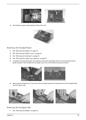
... page 54. 3. See "Removing the Battery" on page 63. 5. See "Removing the Upper Case Assemly" on page 50. 2. Removing the Touchpad Board 1. See "Removing the Keyboard" on the back as the picture shows. 6. To detach the touch pad board, first disconnect the touch pad cable from the upper case. 4.
... page 54. 3. See "Removing the Battery" on page 63. 5. See "Removing the Upper Case Assemly" on page 50. 2. Removing the Touchpad Board 1. See "Removing the Keyboard" on the back as the picture shows. 6. To detach the touch pad board, first disconnect the touch pad cable from the upper case. 4.
Aspire 1360 - 1520 Service Guide
Page 74
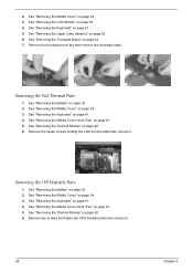
... 1. See "Removing the Middle Cover Hook /Fan" on page 63. 6. See "Removing the Thermal Module" on page 61. 5. See "Removing the Keyboard" on page 62. 6. Remove the seven screws holding the VGA thermal plate then remove it . 65 Chapter 3 Remove two screws that fasten the CPU ... "Removing the LCD Module" on page 64. 7. Removing the CPU Heatsink Plate 1. See "Removing the Touchpad Board" on page 55. 4. See "Removing the Keyboard" on page 62. 6. See "Removing the Thermal Module" on page 61. 4. Remove the touchpad scroll key then remove the touchpad cable. 2. See "Removing the...
... 1. See "Removing the Middle Cover Hook /Fan" on page 63. 6. See "Removing the Thermal Module" on page 61. 5. See "Removing the Keyboard" on page 62. 6. Remove the seven screws holding the VGA thermal plate then remove it . 65 Chapter 3 Remove two screws that fasten the CPU ... "Removing the LCD Module" on page 64. 7. Removing the CPU Heatsink Plate 1. See "Removing the Touchpad Board" on page 55. 4. See "Removing the Keyboard" on page 62. 6. See "Removing the Thermal Module" on page 61. 4. Remove the touchpad scroll key then remove the touchpad cable. 2. See "Removing the...

Aspire 1360 - 1520 Service Guide
Page 75
Removing the ODD Module(1) 1. See "Removing the Keyboard" on page 63. See "Removing the Upper Case Assemly" on page 61. 4. See "Removing the Battery" on the bottom. Remove the screw that fasten the ...
Removing the ODD Module(1) 1. See "Removing the Keyboard" on page 63. See "Removing the Upper Case Assemly" on page 61. 4. See "Removing the Battery" on the bottom. Remove the screw that fasten the ...


