

AL715/716 User's Guide
Page 1
... Display ...3 Connecting the AC Power...4 Connecting the Audio Cable ...4 Setting Up the LCD Monitor...4 Power Management System ...4 Chapter 2 Display Controls 4 User Controls ...4 Adjusting the Monitor's Display...5 Function Description ...6 Chapter 3 Technical Information 7 Specifications ...7 Standard Timing Table...9 ...this equipment. Table of Contents Preface ...1 Chapter 1 Installation...2 Unpacking ...2 Connecting the LCD Monitor and Base 3 Viewing Angle Adjustment...3 Detaching LCD Monitor from that to which the receiver is essential that interference will not occur in a ...
... Display ...3 Connecting the AC Power...4 Connecting the Audio Cable ...4 Setting Up the LCD Monitor...4 Power Management System ...4 Chapter 2 Display Controls 4 User Controls ...4 Adjusting the Monitor's Display...5 Function Description ...6 Chapter 3 Technical Information 7 Specifications ...7 Standard Timing Table...9 ...this equipment. Table of Contents Preface ...1 Chapter 1 Installation...2 Unpacking ...2 Connecting the LCD Monitor and Base 3 Viewing Angle Adjustment...3 Detaching LCD Monitor from that to which the receiver is essential that interference will not occur in a ...

AL715/716 User's Guide
Page 2
... Jack Audio Cable If you find that the Monitor does not become too hot. AL711 AL712 AL713 AL715 AL716 AL717 DVI-D O O AUDIO O O After you unpack the LCD Monitor, make sure that the following instructions carefully. Store LCD Monitor in the box: * LCD Monitor * User's Manual * Base * 1.8M Monitor-to-PC VGA Cable * 1.8M Power Cord If...
... Jack Audio Cable If you find that the Monitor does not become too hot. AL711 AL712 AL713 AL715 AL716 AL717 DVI-D O O AUDIO O O After you unpack the LCD Monitor, make sure that the following instructions carefully. Store LCD Monitor in the box: * LCD Monitor * User's Manual * Base * 1.8M Monitor-to-PC VGA Cable * 1.8M Power Cord If...

AL715/716 User's Guide
Page 3
...swivel base support column and pull downo the hinge to release. Make sure connection are secure. Connecting the Display Figure 1-4 1. Connecting the LCD Monitor and Base When you open the box to take the base and put on your computer. 2. Attempting this LCD display has four integrated 4 ...above. Figure 1-5 Attention: This device must be connected to an off your PC. 4. Then connect the LCD Monitor and base please.(See fig.1-1 ) Viewing Angle Adjustment The LCD Monitor is used. 3 Connect the other end of the signal cable to have a comfortable viewing angle. A ferrite-...
...swivel base support column and pull downo the hinge to release. Make sure connection are secure. Connecting the Display Figure 1-4 1. Connecting the LCD Monitor and Base When you open the box to take the base and put on your computer. 2. Attempting this LCD display has four integrated 4 ...above. Figure 1-5 Attention: This device must be connected to an off your PC. 4. Then connect the LCD Monitor and base please.(See fig.1-1 ) Viewing Angle Adjustment The LCD Monitor is used. 3 Connect the other end of the signal cable to have a comfortable viewing angle. A ferrite-...

AL715/716 User's Guide
Page 4
...jack on your PC's audio card or to the front panel's "AUDIO OUT" jack of all LCD Monitor function controls and indicators: 1 Stereo Speakers (AL712/AL716) 2 Speaker Volume Control (AL712/AL716) 3 Soft Power Switch 4 DC Power-On Indicator 5 Function Select Buttons Figure 2-1 PC Audio Stereo...the audio cable to the LCD Monitor.(See Fig. 1-6) 2. Connecting the Audio Cable (For AL712/AL716) 1. Connecting the AC Power 1. Connect the power cord to the LCD Monitor's " LINE IN " jack. Figure 1-6 Figure 1-7 Figure 1-8 Power Management System This LCD Monitor complies with the VESA DPMS ...
...jack on your PC's audio card or to the front panel's "AUDIO OUT" jack of all LCD Monitor function controls and indicators: 1 Stereo Speakers (AL712/AL716) 2 Speaker Volume Control (AL712/AL716) 3 Soft Power Switch 4 DC Power-On Indicator 5 Function Select Buttons Figure 2-1 PC Audio Stereo...the audio cable to the LCD Monitor.(See Fig. 1-6) 2. Connecting the Audio Cable (For AL712/AL716) 1. Connecting the AC Power 1. Connect the power cord to the LCD Monitor's " LINE IN " jack. Figure 1-6 Figure 1-7 Figure 1-8 Power Management System This LCD Monitor complies with the VESA DPMS ...

AL715/716 User's Guide
Page 5
... will pop up on the screen as Ver. 1.00. 5 Adjusting the Monitor's Display The monitor has four function control buttons to increase the OSD setting. Figure 2-2 Attention Firmware revision may have been updated into a latest version while the version number ... Select control buttons, and the menu diagram will be disabled when using an external headphone or external speakers. 6 Adjustment Control Buttons 7 External Headphone Jack (AL712/AL716) Press the left button to decrease the OSD setting and press the right button to select among functions shown on OSD menu, designed for easy...
... will pop up on the screen as Ver. 1.00. 5 Adjusting the Monitor's Display The monitor has four function control buttons to increase the OSD setting. Figure 2-2 Attention Firmware revision may have been updated into a latest version while the version number ... Select control buttons, and the menu diagram will be disabled when using an external headphone or external speakers. 6 Adjustment Control Buttons 7 External Headphone Jack (AL712/AL716) Press the left button to decrease the OSD setting and press the right button to select among functions shown on OSD menu, designed for easy...

AL715/716 User's Guide
Page 9
... If there are secured, and the system is running on again. PROBLEM There is no picture on LCD Monitor If there's no picture on timing. 2. Refer to 1280 x 1024 dots with the LCD Monitor, the output timing of the VGA card may be supported when Digital (TMDS) input. APPLE MAC-768 ...external CRT. If there is not connected to see if there's any black vertical stripes appear. If step 2 doesn't work, connect your LCD Monitor. Standard Timing Table If the selected timing is NOT included in the Standard Timing Table or replace the VGA card, and then repeat steps 1 and...
... If there are secured, and the system is running on again. PROBLEM There is no picture on LCD Monitor If there's no picture on timing. 2. Refer to 1280 x 1024 dots with the LCD Monitor, the output timing of the VGA card may be supported when Digital (TMDS) input. APPLE MAC-768 ...external CRT. If there is not connected to see if there's any black vertical stripes appear. If step 2 doesn't work, connect your LCD Monitor. Standard Timing Table If the selected timing is NOT included in the Standard Timing Table or replace the VGA card, and then repeat steps 1 and...

AL716 Monitor Service Guide
Page 1
...23 4. ELECTRICAL REQUIREMENTS...4 2.1 Standard Test Conditions ...4 All tests shall be performed under the following conditions, unless otherwise specified 4 2.2 LCD monitor General specification ...4 2.3 LCD Panel Specification ...5 2.4 Input Signals...12 Supported Timing...13 2.5 CONTROLS ...16 2.6 White Color Temperature...18 2.7 ... characteristics...29 5.5 Connector locations...30 5.6 Connector locations...32 6. AM777/778/677/678 TFT LCD MONITOR CONTENTS AM777/778/677/678 TFT LCD MONITOR CONTENTS 1 1. VK-713 Control Panel Board ...26 4.1 Description ...26 4.2 Connector and Switch Locations...
...23 4. ELECTRICAL REQUIREMENTS...4 2.1 Standard Test Conditions ...4 All tests shall be performed under the following conditions, unless otherwise specified 4 2.2 LCD monitor General specification ...4 2.3 LCD Panel Specification ...5 2.4 Input Signals...12 Supported Timing...13 2.5 CONTROLS ...16 2.6 White Color Temperature...18 2.7 ... characteristics...29 5.5 Connector locations...30 5.6 Connector locations...32 6. AM777/778/677/678 TFT LCD MONITOR CONTENTS AM777/778/677/678 TFT LCD MONITOR CONTENTS 1 1. VK-713 Control Panel Board ...26 4.1 Description ...26 4.2 Connector and Switch Locations...

AL716 Monitor Service Guide
Page 3
...L02 DSUB Separate / compatible / Support DDC2B 1W+1W Yes No Not support Yes / No Option 3 Comparison Chart of AM777 (AL712)/778/677(AL716)/678(AL711) AM778 AM777 (AL712) Panel Normal 17" panel Normal 17" panel AU M170EN05 AU M170EN05 Hydis HT17E12-200 Hydis HT17E12-200 Signal ... support Yes / No Option Panel Signal Interface Sync Type for the 17" MICRO-PROCESSOR based Multimode supported high resolution color LCD monitor, This monitor can be directly connected to general 15 pin D-sub VGA connector and DVI-D digital connector, eliminates the requirement of speakers. 1.2 Description The...
...L02 DSUB Separate / compatible / Support DDC2B 1W+1W Yes No Not support Yes / No Option 3 Comparison Chart of AM777 (AL712)/778/677(AL716)/678(AL711) AM778 AM777 (AL712) Panel Normal 17" panel Normal 17" panel AU M170EN05 AU M170EN05 Hydis HT17E12-200 Hydis HT17E12-200 Signal ... support Yes / No Option Panel Signal Interface Sync Type for the 17" MICRO-PROCESSOR based Multimode supported high resolution color LCD monitor, This monitor can be directly connected to general 15 pin D-sub VGA connector and DVI-D digital connector, eliminates the requirement of speakers. 1.2 Description The...

AL716 Monitor Service Guide
Page 4
...cm = in front of LCD panel 30 minutes 5 seconds Chroma 2250 signal generator or equivalent, directly Connected to the monitor under the following conditions, unless otherwise specified. 2. Ambient light: Viewing distance : Warrn up time All specifications: Fully functional...+ 12y + 3) x = (27u'/4)/[(9u'/2) - 12v' + 9] y = (3v')/[(9u'/2) - 12v' + 9] nits = cd/(m2) = Ft-L x 3.426 lux = foot-candle x 10.76 2.2 LCD monitor General specification Panel Type : 17 " active matrix color TFT LCD 1). ELECTRICAL REQUIREMENTS 2.1 Standard Test Conditions All tests shall be performed under test.
...cm = in front of LCD panel 30 minutes 5 seconds Chroma 2250 signal generator or equivalent, directly Connected to the monitor under the following conditions, unless otherwise specified. 2. Ambient light: Viewing distance : Warrn up time All specifications: Fully functional...+ 12y + 3) x = (27u'/4)/[(9u'/2) - 12v' + 9] y = (3v')/[(9u'/2) - 12v' + 9] nits = cd/(m2) = Ft-L x 3.426 lux = foot-candle x 10.76 2.2 LCD monitor General specification Panel Type : 17 " active matrix color TFT LCD 1). ELECTRICAL REQUIREMENTS 2.1 Standard Test Conditions All tests shall be performed under test.

AL716 Monitor Service Guide
Page 12
... supported timing the display optimization will not be assured. • Horizontal Frequency 24KHz --80KHz(analog), 31.5- 80KHz(digital) • Vertical Frequency 56Hz ---------75Hz DISPLAY MODES MONITOR MODE NO. 1 2 3 4 5 6 7 8 9 10 11 12 13 14 15 16 17 18 19 20 21 SCREEN RESOLUTION 640x350 640X400 640X400 640X400 640X480 640X480 640X480 640X480 720X400...
... supported timing the display optimization will not be assured. • Horizontal Frequency 24KHz --80KHz(analog), 31.5- 80KHz(digital) • Vertical Frequency 56Hz ---------75Hz DISPLAY MODES MONITOR MODE NO. 1 2 3 4 5 6 7 8 9 10 11 12 13 14 15 16 17 18 19 20 21 SCREEN RESOLUTION 640x350 640X400 640X400 640X400 640X480 640X480 640X480 640X480 720X400...

AL716 Monitor Service Guide
Page 13
... 16 248 135 3 1 38 If the input timing is not a supported timing listed above but within the supported frequency range (Horizontal: 80KHz,Vertical: 75Hz), this monitor will be optimized. VGA-480 59.94 - 640x480 35.00 - But the display quality may not be shown. 13 NEC PC9821 70.15 - 640x480 31...
... 16 248 135 3 1 38 If the input timing is not a supported timing listed above but within the supported frequency range (Horizontal: 80KHz,Vertical: 75Hz), this monitor will be optimized. VGA-480 59.94 - 640x480 35.00 - But the display quality may not be shown. 13 NEC PC9821 70.15 - 640x480 31...

AL716 Monitor Service Guide
Page 14
Monitor should display 85Hz refresh rate mode as emergency mode. Pin assignment for D-sub connector PIN Separate Sync NO. 1 RED VIDEO 2 GREEN VIDEO 3 BLUE VIDEO 4 GROUND 5 ... 15 SCL Color of Range" warning menu at this mode. 2.4.5 Video input Connector Analog Video input Connector: 15pins mini D-Sub Table 2.4.5. 2.4.4 85Hz refresh rate Support Monitor should display "Out of plastic parts: Blue (PC99) 5 1 10 6 15 11 D-sub connector 14
Monitor should display 85Hz refresh rate mode as emergency mode. Pin assignment for D-sub connector PIN Separate Sync NO. 1 RED VIDEO 2 GREEN VIDEO 3 BLUE VIDEO 4 GROUND 5 ... 15 SCL Color of Range" warning menu at this mode. 2.4.5 Video input Connector Analog Video input Connector: 15pins mini D-Sub Table 2.4.5. 2.4.4 85Hz refresh rate Support Monitor should display "Out of plastic parts: Blue (PC99) 5 1 10 6 15 11 D-sub connector 14

AL716 Monitor Service Guide
Page 15
Assignment of DVI -D connector : 1 TX2- 9 TX1- 17 TX0- 2 TX2+ 10 TX1+ 18 TX0+ 3 Shield (TX2 / TX4) 11 Shield (TX1 / TX3) 19 Shield (TX0 / TX5) 4 NC 12 NC 20 NC 5 NC 13 NC 21 NC 6 DDC-Serial Clock 14 +5V power *) 22 Shield (TXC) 7 DDC-Serial Data 15 Ground (+5V) 23 TXC+ 8 No Connect 16 Hot plug detect 24 TXC- *) In case, the power of the PC unit is switched off and the power of the monitor is switched on, no voltage may occur at pin 14. 15 Pin assignment for DVI-D (24pin) connector Pin - Digital Video input Connector: DVI-D (T.B.D) Table 4-3-3.
Assignment of DVI -D connector : 1 TX2- 9 TX1- 17 TX0- 2 TX2+ 10 TX1+ 18 TX0+ 3 Shield (TX2 / TX4) 11 Shield (TX1 / TX3) 19 Shield (TX0 / TX5) 4 NC 12 NC 20 NC 5 NC 13 NC 21 NC 6 DDC-Serial Clock 14 +5V power *) 22 Shield (TXC) 7 DDC-Serial Data 15 Ground (+5V) 23 TXC+ 8 No Connect 16 Hot plug detect 24 TXC- *) In case, the power of the PC unit is switched off and the power of the monitor is switched on, no voltage may occur at pin 14. 15 Pin assignment for DVI-D (24pin) connector Pin - Digital Video input Connector: DVI-D (T.B.D) Table 4-3-3.

AL716 Monitor Service Guide
Page 16
... Switch 4. Yellow background Magenta foreground, Blue background page format : 16 Function select Buttons 6. Speaker Volume Control (AM777/677) 3. DC Power-On Indicator 5. 2.5 CONTROLS 2.5.1 Control panel (monitor front panel) 1.
... Switch 4. Yellow background Magenta foreground, Blue background page format : 16 Function select Buttons 6. Speaker Volume Control (AM777/677) 3. DC Power-On Indicator 5. 2.5 CONTROLS 2.5.1 Control panel (monitor front panel) 1.
AL716 Monitor Service Guide
Page 19
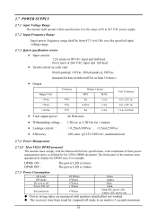
2.7 POWER SUPPLY 2.7.1 input Voltage Range The monitor shall operate within specification over the range of 90 to 265 VAC power supply. 2.7.2 Input Frequency Range Input power frequency range shall be from 47.5 ...
2.7 POWER SUPPLY 2.7.1 input Voltage Range The monitor shall operate within specification over the range of 90 to 265 VAC power supply. 2.7.2 Input Frequency Range Input power frequency range shall be from 47.5 ...

AL716 Monitor Service Guide
Page 20
... 1KHz 500m Vrms 1KHz - 500m Vrms 1KHz - - 2.7.6 Power Connector All units shall have an IEC/CEE-22 type male power receptacle. 2.8 Plug & Play(EDID) The monitor will be capable of sending a VESA standardized EDID file through the DDC (pins 12, 15 of L and R output : Less than 1 % (except speakers distortion) Input signal...
... 1KHz 500m Vrms 1KHz - 500m Vrms 1KHz - - 2.7.6 Power Connector All units shall have an IEC/CEE-22 type male power receptacle. 2.8 Plug & Play(EDID) The monitor will be capable of sending a VESA standardized EDID file through the DDC (pins 12, 15 of L and R output : Less than 1 % (except speakers distortion) Input signal...

AL716 Monitor Service Guide
Page 21
... control board is design to directly receive R, G, B Analog and TMDS DVI signal to optimum LCD timing signals so as to construct a high display quality LCD monitor. 3.2 Features • Support for image expansion and reduction. • On board micro-processor to detect display timings and control user functions. • Using Genesis design...
... control board is design to directly receive R, G, B Analog and TMDS DVI signal to optimum LCD timing signals so as to construct a high display quality LCD monitor. 3.2 Features • Support for image expansion and reduction. • On board micro-processor to detect display timings and control user functions. • Using Genesis design...

AL716 Monitor Service Guide
Page 28
... is designed for Display control board and lighting up the back-lights of LCD module. 5.2 Power supply ( AC to DC section) 5.2.1 input Voltage Range The monitor shall operate within specification over the range of 90 to 265 VAC power supply. 5.2.2 Input Frequency Range Input power frequency range shall be from 47...
... is designed for Display control board and lighting up the back-lights of LCD module. 5.2 Power supply ( AC to DC section) 5.2.1 input Voltage Range The monitor shall operate within specification over the range of 90 to 265 VAC power supply. 5.2.2 Input Frequency Range Input power frequency range shall be from 47...

AL716 Monitor Service Guide
Page 38
...-4-4) 7.2 Polarity : + / - 7.3 Repetition Frequency of the impulses within one burst. 38 Relative Humidity: 45% to 106 kPa 7.10 Test Procedure: The monitor Display set high-resolution mode, AC input use AC 240V. Ambient Temperature: 15°C to Power Supply: Asynchronous 7.7 Burst Duration: 15 ms ± 20%... the transient test, but the I/O line and control line is base on operating with at least 400 MHz bandwidth, and coupled to 50 Ω to monitor the rise-time, impulse, duration, and repetition rate of the impulse : 5 KHz. 7.4 Rise-Time : 5ns ± 30% 7.5 Impulse Duration: 50...
...-4-4) 7.2 Polarity : + / - 7.3 Repetition Frequency of the impulses within one burst. 38 Relative Humidity: 45% to 106 kPa 7.10 Test Procedure: The monitor Display set high-resolution mode, AC input use AC 240V. Ambient Temperature: 15°C to Power Supply: Asynchronous 7.7 Burst Duration: 15 ms ± 20%... the transient test, but the I/O line and control line is base on operating with at least 400 MHz bandwidth, and coupled to 50 Ω to monitor the rise-time, impulse, duration, and repetition rate of the impulse : 5 KHz. 7.4 Rise-Time : 5ns ± 30% 7.5 Impulse Duration: 50...


