

User Manual
Page 5
... and Utilities Operation 41 3.1 Installing Drivers 41 3.2 A-Tuning 42 3.3 Intel® Rapid Start Technology 48 3.4 Intel® Smart Connect Technology 53 3.5 ASRock APP Shop 58 3.5.1 UI Overview 58 3.5.2 Apps 59 3.5.3 BIOS & Drivers 62 3.5.4 Setting 63 3.6 Start8 64 Chapter 4 UEFI SETUP UTILITY 67 4.1 Introduction 67 4.1.1 UEFI Menu Bar 67 4.1.2 Navigation Keys 68 4.2 Main...
... and Utilities Operation 41 3.1 Installing Drivers 41 3.2 A-Tuning 42 3.3 Intel® Rapid Start Technology 48 3.4 Intel® Smart Connect Technology 53 3.5 ASRock APP Shop 58 3.5.1 UI Overview 58 3.5.2 Apps 59 3.5.3 BIOS & Drivers 62 3.5.4 Setting 63 3.6 Start8 64 Chapter 4 UEFI SETUP UTILITY 67 4.1 Introduction 67 4.1.1 UEFI Menu Bar 67 4.1.2 Navigation Keys 68 4.2 Main...
User Manual
Page 7
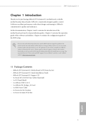
.... Chapter 3 contains the operation guide of the BIOS setup. Z97 Extreme6/3.1 Chapter 1 Introduction hank you for mini-PCIe Slot 1 English Chapter 4 contains the coniguration guide of the sotware and utilities. ASRock website http://www.asrock.com. 1.1 Package Contents • ASRock Z97 Extreme6/3.1 Motherboard (ATX Form Factor) • ASRock Z97 Extreme6/3.1 Quick Installation Guide • ASRock Z97 Extreme6/3.1 Support CD • 4 x Serial ATA (SATA) Data...
.... Chapter 3 contains the operation guide of the BIOS setup. Z97 Extreme6/3.1 Chapter 1 Introduction hank you for mini-PCIe Slot 1 English Chapter 4 contains the coniguration guide of the sotware and utilities. ASRock website http://www.asrock.com. 1.1 Package Contents • ASRock Z97 Extreme6/3.1 Motherboard (ATX Form Factor) • ASRock Z97 Extreme6/3.1 Quick Installation Guide • ASRock Z97 Extreme6/3.1 Support CD • 4 x Serial ATA (SATA) Data...

User Manual
Page 11
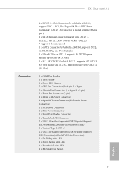
Z97 Extreme6/3.1 • 4 x SATA3 6.0 Gb/s Connectors by ASMedia ASM1061, support NCQ, AHCI, Hot Plug and ASRock HDD Saver Technology (SATA3_A4 connector is shared with the eSATA port) • 1 x SATA Express Connector (shared with ... 1 x hunderbolt AIC Connector • 2 x USB 2.0 Headers (support 4 USB 2.0 ports) (Supports ESD Protection (ASRock Full Spike Protection)) • 1 x Vertical Type A USB 2.0 • 2 x USB 3.0 Headers (support 4 USB 3.0 ports) (Supports ESD Protection (ASRock Full Spike Protection)) • 1 x Dr. Debug with LED • 1 x Power Switch with LED • ...
Z97 Extreme6/3.1 • 4 x SATA3 6.0 Gb/s Connectors by ASMedia ASM1061, support NCQ, AHCI, Hot Plug and ASRock HDD Saver Technology (SATA3_A4 connector is shared with the eSATA port) • 1 x SATA Express Connector (shared with ... 1 x hunderbolt AIC Connector • 2 x USB 2.0 Headers (support 4 USB 2.0 ports) (Supports ESD Protection (ASRock Full Spike Protection)) • 1 x Vertical Type A USB 2.0 • 2 x USB 3.0 Headers (support 4 USB 3.0 ports) (Supports ESD Protection (ASRock Full Spike Protection)) • 1 x Dr. Debug with LED • 1 x Power Switch with LED • ...

User Manual
Page 12
... information, please visit our website: http://www.asrock.com Please realize that Windows® cannot use ASRock XFast RAM to utilize the memory that there is a certain risk involved with multilingual GUI support (1 x Main BIOS and 1 x Backup BIOS) • Supports Secure Backup UEFI Technology ...® 64-bit operating systems do not have such limitations. BIOS Feature Hardware Monitor OS Certiications • 2 x 64Mb AMI UEFI Legal BIOS with overclocking, including adjusting the setting in the BIOS, applying Untied Overclocking Technology, or using third-party overclocking tools....
... information, please visit our website: http://www.asrock.com Please realize that Windows® cannot use ASRock XFast RAM to utilize the memory that there is a certain risk involved with multilingual GUI support (1 x Main BIOS and 1 x Backup BIOS) • Supports Secure Backup UEFI Technology ...® 64-bit operating systems do not have such limitations. BIOS Feature Hardware Monitor OS Certiications • 2 x 64Mb AMI UEFI Legal BIOS with overclocking, including adjusting the setting in the BIOS, applying Untied Overclocking Technology, or using third-party overclocking tools....

User Manual
Page 14
...) 14 SATA3 Connectors (SATA3_2_5) 15 SATA Express Connector (SATAE_1) 16 Chassis Fan Connector (CHA_FAN1) 17 Chassis Speaker Header (SPEAKER1) 18 Power LED Header (PLED1) 19 BIOS Selection Switch (BIOS_SEL1) 20 Power Switch (PWRBTN1) 21 Reset Switch (RSTBTN1) 22 HDD Saver Connector (SATA_PWR_1) 23 System Panel Header (PANEL1) 24 Vertical Type A USB...
...) 14 SATA3 Connectors (SATA3_2_5) 15 SATA Express Connector (SATAE_1) 16 Chassis Fan Connector (CHA_FAN1) 17 Chassis Speaker Header (SPEAKER1) 18 Power LED Header (PLED1) 19 BIOS Selection Switch (BIOS_SEL1) 20 Power Switch (PWRBTN1) 21 Reset Switch (RSTBTN1) 22 HDD Saver Connector (SATA_PWR_1) 23 System Panel Header (PANEL1) 24 Vertical Type A USB...

User Manual
Page 25
... irst, and then shut it down before you do not clear the CMOS right ater you update the BIOS. Ater waiting for 5 seconds. he illustration shows a 3-pin jumper whose pin1 and pin2 are setup. Z97 Extreme6/3.1 2.5 Jumpers Setup he illustration shows how jumpers are "Short" when a jumper cap is placed on the pins...
... irst, and then shut it down before you do not clear the CMOS right ater you update the BIOS. Ater waiting for 5 seconds. he illustration shows a 3-pin jumper whose pin1 and pin2 are setup. Z97 Extreme6/3.1 2.5 Jumpers Setup he illustration shows how jumpers are "Short" when a jumper cap is placed on the pins...

User Manual
Page 32
... next system boot. English 26 his function is corrupted or damaged, just lip the BIOS Selection Switch to "B", then the backup BIOS will work on the primary BIOS. Users may refer to the BIOS LEDs (BIOS_A_LED or BIOS_B_LED) to identify which enhances the safety and stability of your ... Switch, allowing users to quickly turn on/of the system. his motherboard has two BIOS chips, a primary BIOS (BIOS_A) and a backup BIOS (BIOS_ B), which BIOS is currently activated. However, if the primary BIOS is workable only when you power of your system. Ater that, use "Secure Backup UEFI" in ...
... next system boot. English 26 his function is corrupted or damaged, just lip the BIOS Selection Switch to "B", then the backup BIOS will work on the primary BIOS. Users may refer to the BIOS LEDs (BIOS_A_LED or BIOS_B_LED) to identify which enhances the safety and stability of your ... Switch, allowing users to quickly turn on/of the system. his motherboard has two BIOS chips, a primary BIOS (BIOS_A) and a backup BIOS (BIOS_ B), which BIOS is currently activated. However, if the primary BIOS is workable only when you power of your system. Ater that, use "Secure Backup UEFI" in ...

User Manual
Page 52
Tech Service Contact Tech Service if you have problems with details of BIOS or drivers. Live Update Check for newer versions of the problem. 46 English Please leave your contact information along with your computer.
Tech Service Contact Tech Service if you have problems with details of BIOS or drivers. Live Update Check for newer versions of the problem. 46 English Please leave your contact information along with your computer.

User Manual
Page 55
Enter Windows 8.1/8/7. Press F2 to enter BIOS, then go to Advanced ‐> Storage Coniguration and change SATA Mode to save changes and exit. 5. Windows will automatically create a hidden partition according to your ... your settings. he system will discover the new device and install AHCI drivers automatically. 3.3.2 Setup Guide Coniguring Rapid Start Step 1 Run ASRock Rapid Start utility from Start -> All Programs -> ASRock Utility. Z97 Extreme6/3.1 3. Step 2 If you have more than one hard drives in your system, you must select one, then choose the Partition Size...
Enter Windows 8.1/8/7. Press F2 to enter BIOS, then go to Advanced ‐> Storage Coniguration and change SATA Mode to save changes and exit. 5. Windows will automatically create a hidden partition according to your ... your settings. he system will discover the new device and install AHCI drivers automatically. 3.3.2 Setup Guide Coniguring Rapid Start Step 1 Run ASRock Rapid Start utility from Start -> All Programs -> ASRock Utility. Z97 Extreme6/3.1 3. Step 2 If you have more than one hard drives in your system, you must select one, then choose the Partition Size...

User Manual
Page 68
Please update them all soon. Click on Step 2 to start the update process. 62 English Step 3 Click Update to see more items you will see a list of recommended or critical updates for the BIOS or drivers. Click to select one or more details. Step 1 Please check the item information before update. 3.5.3 BIOS & Drivers Installing BIOS or Drivers When the "BIOS & Drivers" tab is selected, you want to update.
Please update them all soon. Click on Step 2 to start the update process. 62 English Step 3 Click Update to see more items you will see a list of recommended or critical updates for the BIOS or drivers. Click to select one or more details. Step 1 Please check the item information before update. 3.5.3 BIOS & Drivers Installing BIOS or Drivers When the "BIOS & Drivers" tab is selected, you want to update.
User Manual
Page 75
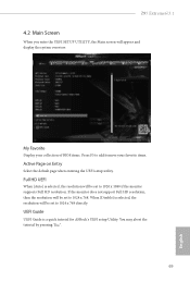
.... You may abort the tutorial by pressing "Esc". 69 English When [Disable] is a quick tutorial for ASRock's UEFI setup Utility. UEFI Guide UEFI Guide is selected, the resolution will be set to 1024 x 768. Z97 Extreme6/3.1 4.2 Main Screen When you enter the UEFI SETUP UTILITY, the Main screen will be set to add... UEFI setup utility. Full HD UEFI When [Auto] is selected, the resolution will appear and display the system overview. My Favorite Display your collection of BIOS items. Press F5 to 1024 x 768 directly.
.... You may abort the tutorial by pressing "Esc". 69 English When [Disable] is a quick tutorial for ASRock's UEFI setup Utility. UEFI Guide UEFI Guide is selected, the resolution will be set to 1024 x 768. Z97 Extreme6/3.1 4.2 Main Screen When you enter the UEFI SETUP UTILITY, the Main screen will be set to add... UEFI setup utility. Full HD UEFI When [Auto] is selected, the resolution will appear and display the system overview. My Favorite Display your collection of BIOS items. Press F5 to 1024 x 768 directly.

User Manual
Page 98
Set [Smart Auto] to automatically enable the USB 3.0 driver ater entering the OS (USB 3.0 is enabled in BIOS). Set [Auto] to keep the USB 3.0 driver enabled (Must install driver to support USB devices under Windows® 7). If you encounter USB compatibility ...UEFI setup and Windows/Linux operating systems only. 92 English Set [Enabled] to keep the USB 3.0 driver enabled ater rebooting (USB 3.0 is disabled in BIOS). Legacy USB Support Enable or disable Legacy OS Support for USB 3.0 devices. 4.4.9 USB Coniguration USB Controller Enable or disable all the USB ports. Intel USB...
Set [Smart Auto] to automatically enable the USB 3.0 driver ater entering the OS (USB 3.0 is enabled in BIOS). Set [Auto] to keep the USB 3.0 driver enabled (Must install driver to support USB devices under Windows® 7). If you encounter USB compatibility ...UEFI setup and Windows/Linux operating systems only. 92 English Set [Enabled] to keep the USB 3.0 driver enabled ater rebooting (USB 3.0 is disabled in BIOS). Legacy USB Support Enable or disable Legacy OS Support for USB 3.0 devices. 4.4.9 USB Coniguration USB Controller Enable or disable all the USB ports. Intel USB...

User Manual
Page 103
...to the secondary lash ROM. Network Coniguration Use this function. Internet Setting Enable or disable sound efects in your UEFI. Internet Flash ASRock Internet Flash downloads and updates the latest UEFI irmware version from our servers for Internet Flash. Please setup network coniguration before using this... other lash ROM and execute Secure Backup UEFI to duplicate the current working ROM image to download the UEFI irmware. 97 English Z97 Extreme6/3.1 Instant Flash Save UEFI iles in your USB storage device and run Instant Flash to update your USB pen drive before using Internet...
...to the secondary lash ROM. Network Coniguration Use this function. Internet Setting Enable or disable sound efects in your UEFI. Internet Flash ASRock Internet Flash downloads and updates the latest UEFI irmware version from our servers for Internet Flash. Please setup network coniguration before using this... other lash ROM and execute Secure Backup UEFI to duplicate the current working ROM image to download the UEFI irmware. 97 English Z97 Extreme6/3.1 Instant Flash Save UEFI iles in your USB storage device and run Instant Flash to update your USB pen drive before using Internet...

Quick Installation Guide
Page 4
...) 14 SATA3 Connectors (SATA3_2_5) 15 SATA Express Connector (SATAE_1) 16 Chassis Fan Connector (CHA_FAN1) 17 Chassis Speaker Header (SPEAKER1) 18 Power LED Header (PLED1) 19 BIOS Selection Switch (BIOS_SEL1) 20 Power Switch (PWRBTN1) 21 Reset Switch (RSTBTN1) 22 HDD Saver Connector (SATA_PWR_1) 23 System Panel Header (PANEL1) 24 Vertical Type A USB...
...) 14 SATA3 Connectors (SATA3_2_5) 15 SATA Express Connector (SATAE_1) 16 Chassis Fan Connector (CHA_FAN1) 17 Chassis Speaker Header (SPEAKER1) 18 Power LED Header (PLED1) 19 BIOS Selection Switch (BIOS_SEL1) 20 Power Switch (PWRBTN1) 21 Reset Switch (RSTBTN1) 22 HDD Saver Connector (SATA_PWR_1) 23 System Panel Header (PANEL1) 24 Vertical Type A USB...

Quick Installation Guide
Page 7
... purchasing ASRock Z97 Extreme6/3.1 motherboard, a reliable motherboard produced under ASRock's consistently stringent quality control. You may ind the latest VGA cards and CPU support list on ASRock's website without notice. In case any modiications of this documentation occur, the updated version will be available on ASRock's website as well. Because the motherboard speciications and the BIOS sotware...
... purchasing ASRock Z97 Extreme6/3.1 motherboard, a reliable motherboard produced under ASRock's consistently stringent quality control. You may ind the latest VGA cards and CPU support list on ASRock's website without notice. In case any modiications of this documentation occur, the updated version will be available on ASRock's website as well. Because the motherboard speciications and the BIOS sotware...
Quick Installation Guide
Page 11
Z97 Extreme6/3.1 Connector • 4 x SATA3 6.0 Gb/s Connectors by ASMedia ASM1061, support NCQ, AHCI, Hot Plug and ASRock HDD Saver Technology (SATA3_A4 connector is shared with the eSATA port) • 1 x SATA Express Connector (shared ...1 x hunderbolt AIC Connector • 2 x USB 2.0 Headers (support 4 USB 2.0 ports) (Supports ESD Protection (ASRock Full Spike Protection)) • 1 x Vertical Type A USB 2.0 • 2 x USB 3.0 Headers (support 4 USB 3.0 ports) (Supports ESD Protection (ASRock Full Spike Protection)) • 1 x Dr. Debug with LED • 1 x Power Switch with LED •...
Z97 Extreme6/3.1 Connector • 4 x SATA3 6.0 Gb/s Connectors by ASMedia ASM1061, support NCQ, AHCI, Hot Plug and ASRock HDD Saver Technology (SATA3_A4 connector is shared with the eSATA port) • 1 x SATA Express Connector (shared ...1 x hunderbolt AIC Connector • 2 x USB 2.0 Headers (support 4 USB 2.0 ports) (Supports ESD Protection (ASRock Full Spike Protection)) • 1 x Vertical Type A USB 2.0 • 2 x USB 3.0 Headers (support 4 USB 3.0 ports) (Supports ESD Protection (ASRock Full Spike Protection)) • 1 x Dr. Debug with LED • 1 x Power Switch with LED •...

Quick Installation Guide
Page 12
.../EuP ready power supply is required) * For detailed product information, please visit our website: http://www.asrock.com Please realize that Windows® cannot use ASRock XFast RAM to limitation, the actual memory size may afect your system's stability, or even cause damage to... adjust chassis fan speed by overclocking. Due to utilize the memory that there is a certain risk involved with multilingual GUI support (1 x Main BIOS and 1 x Backup BIOS) • Supports Secure Backup UEFI Technology • ACPI 1.1 Compliant wake up events • SMBIOS 2.3.1 Support • CPU, DRAM, ...
.../EuP ready power supply is required) * For detailed product information, please visit our website: http://www.asrock.com Please realize that Windows® cannot use ASRock XFast RAM to limitation, the actual memory size may afect your system's stability, or even cause damage to... adjust chassis fan speed by overclocking. Due to utilize the memory that there is a certain risk involved with multilingual GUI support (1 x Main BIOS and 1 x Backup BIOS) • Supports Secure Backup UEFI Technology • ACPI 1.1 Compliant wake up events • SMBIOS 2.3.1 Support • CPU, DRAM, ...

Quick Installation Guide
Page 21
... are setup. Clear CMOS Jumper (CLRCMOS1) (see p.1, No. 9) Default Clear CMOS CLRCMOS1 allows you to clear the CMOS when you just inish updating the BIOS, you must boot up the system irst, and then shut it down before you do not clear the CMOS right ater you need to clear... Clear CMOS Switch has the same function as the Clear CMOS jumper. Ater waiting for 5 seconds. English 19 However, please do the clear-CMOS action. Z97 Extreme6/3.1 2.5 Jumpers Setup he illustration shows how jumpers are "Short" when a jumper cap is placed on the pins, the jumper is "Short". To clear and ...
... are setup. Clear CMOS Jumper (CLRCMOS1) (see p.1, No. 9) Default Clear CMOS CLRCMOS1 allows you to clear the CMOS when you just inish updating the BIOS, you must boot up the system irst, and then shut it down before you do not clear the CMOS right ater you need to clear... Clear CMOS Switch has the same function as the Clear CMOS jumper. Ater waiting for 5 seconds. English 19 However, please do the clear-CMOS action. Z97 Extreme6/3.1 2.5 Jumpers Setup he illustration shows how jumpers are "Short" when a jumper cap is placed on the pins, the jumper is "Short". To clear and ...

Quick Installation Guide
Page 28
...power of your system. For safety issues, users are not able to quickly turn on the next system boot. Users may refer to the BIOS LEDs (BIOS_A_LED or BIOS_B_LED) to identify which enhances the safety and stability of your computer and unplug the power supply. Power Switch (PWRBTN) ... in the UEFI Setup Utility to duplicate a working copy of the system, reset the system, clear the CMOS values or boot from either BIOS A or BIOS B. English 26 BIOS Selection Switch (BIOS_SEL1) (see p.4, No. 16) Clear CMOS Switch allows users to quickly clear the CMOS values. 2.7 Smart Switches he ...
...power of your system. For safety issues, users are not able to quickly turn on the next system boot. Users may refer to the BIOS LEDs (BIOS_A_LED or BIOS_B_LED) to identify which enhances the safety and stability of your computer and unplug the power supply. Power Switch (PWRBTN) ... in the UEFI Setup Utility to duplicate a working copy of the system, reset the system, clear the CMOS values or boot from either BIOS A or BIOS B. English 26 BIOS Selection Switch (BIOS_SEL1) (see p.4, No. 16) Clear CMOS Switch allows users to quickly clear the CMOS values. 2.7 Smart Switches he ...

RAID Installation Guide
Page 1
...; 8.1 / 8.1 64-bit / 8 / 8 64-bit / 7 / 7 64-bit With RAID Functions 7 2.4 Coniguring a RAID array 8 2.4.1 Coniguring a RAID array Using UEFI Setup Utility ...... 9 2.4.2 Coniguring a RAID array Using Intel RAID BIOS ...... 13 3. Guide to SATA Hard Disks Installation 2 1.1 Serial ATA (SATA) Hard Disks Installation 2 2. Guide to SATA Hard Disks Installation and RAID Coniguration 1.
...; 8.1 / 8.1 64-bit / 8 / 8 64-bit / 7 / 7 64-bit With RAID Functions 7 2.4 Coniguring a RAID array 8 2.4.1 Coniguring a RAID array Using UEFI Setup Utility ...... 9 2.4.2 Coniguring a RAID array Using Intel RAID BIOS ...... 13 3. Guide to SATA Hard Disks Installation 2 1.1 Serial ATA (SATA) Hard Disks Installation 2 2. Guide to SATA Hard Disks Installation and RAID Coniguration 1.


