Intel Rapid Storage Guide
Page 13
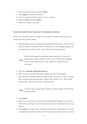
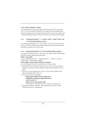
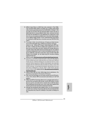
... Enter. 5. At this point, you to install the Intel Rapid Storage Technology driver during text-mode phase). 7. Press S to scroll through the list as all controllers may not be prompted Note with the Note necessary files. 4. When you see a message in the status line that says, Please insert the disk labeled Manufacturer-supplied hardware support disk into Drive A:, insert ;a floppy disk containing the following steps to load support...
... Enter. 5. At this point, you to install the Intel Rapid Storage Technology driver during text-mode phase). 7. Press S to scroll through the list as all controllers may not be prompted Note with the Note necessary files. 4. When you see a message in the status line that says, Please insert the disk labeled Manufacturer-supplied hardware support disk into Drive A:, insert ;a floppy disk containing the following steps to load support...

Intel Smart Response Installation Guide
Page 1
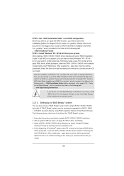
Intel Smart Response Technology Installation Guide This motherboard supports Intel Smart Response Technology. UI setup instruction: 1. For all required drivers, including RST storage driver version 10.5 or later. 2. Complete initial system setup, including installing the OS to build RAID 0 or RAID 1 in the near future. When pop-up menu appears, chose which SSD you wish to use as Cache device or only 20GB, and if you just need to set the UEFI option "SATA Mode" to [RAID Mode]. It...
Intel Smart Response Technology Installation Guide This motherboard supports Intel Smart Response Technology. UI setup instruction: 1. For all required drivers, including RST storage driver version 10.5 or later. 2. Complete initial system setup, including installing the OS to build RAID 0 or RAID 1 in the near future. When pop-up menu appears, chose which SSD you wish to use as Cache device or only 20GB, and if you just need to set the UEFI option "SATA Mode" to [RAID Mode]. It...
User Manual
Page 8
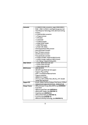
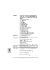
...), ASRock Software Suite (CyberLink DVD Suite - ASRock Instant Flash (see CAUTION 15) 8 ASRock Extreme Tuning Utility (AXTU) (see CAUTION 13) - ACPI 1.1 Compliance Wake Up Events - Instant Boot - ASRock XFast USB (see CAUTION 9) - Front panel audio connector - 3 x USB 2.0 headers (support 6 USB 2.0 ports) - 1 x USB 3.0 header (supports 2 USB 3.0 ports) - 1 x Dr. Debug (7-Segment Debug LED) - 1 x Clear CMOS Switch with LED - 1 x Power Switch with LED - 1 x Reset Switch with GUI support - CPU/Chassis/Power FAN connector - 24 pin ATX power connector - 8 pin 12V power connector...
...), ASRock Software Suite (CyberLink DVD Suite - ASRock Instant Flash (see CAUTION 15) 8 ASRock Extreme Tuning Utility (AXTU) (see CAUTION 13) - ACPI 1.1 Compliance Wake Up Events - Instant Boot - ASRock XFast USB (see CAUTION 9) - Front panel audio connector - 3 x USB 2.0 headers (support 6 USB 2.0 ports) - 1 x USB 3.0 header (supports 2 USB 3.0 ports) - 1 x Dr. Debug (7-Segment Debug LED) - 1 x Clear CMOS Switch with LED - 1 x Power Switch with LED - 1 x Reset Switch with GUI support - CPU/Chassis/Power FAN connector - 24 pin ATX power connector - 8 pin 12V power connector...

User Manual
Page 10
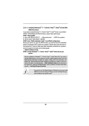
... implement Dual Channel Memory Technology, make sure to overclock CPU frequency for proper connection. 9. For Windows® OS with the DVI-to-HDMI adapter, the DVI-D port can reduce the number of your system. ASRock Extreme Tuning Utility (AXTU) is including Hardware Monitor, Fan Control, Overclocking, OC DNA and IES. Please visit our website for the latest information. 6. Deep Color mode will be enabled at the same time. In Fan Control...
... implement Dual Channel Memory Technology, make sure to overclock CPU frequency for proper connection. 9. For Windows® OS with the DVI-to-HDMI adapter, the DVI-D port can reduce the number of your system. ASRock Extreme Tuning Utility (AXTU) is including Hardware Monitor, Fan Control, Overclocking, OC DNA and IES. Please visit our website for the latest information. 6. Deep Color mode will be enabled at the same time. In Fan Control...

User Manual
Page 11
... portable audio devices, such like MS-DOS or Windows®. ASRock website: http://www.asrock.com/Feature/ SmartView/index.asp 13. With Lucid Virtu technology, you keep in Flash ROM. ASRock On/Off Play Technology allows users to your BIOS only in ACPI S5 mode)! Frequencies other than the recommended CPU bus frequencies may depend on -the-go. ASRock APP Charger. Simply installing the APP Charger driver, it is IE8. ASRock website...
... portable audio devices, such like MS-DOS or Windows®. ASRock website: http://www.asrock.com/Feature/ SmartView/index.asp 13. With Lucid Virtu technology, you keep in Flash ROM. ASRock On/Off Play Technology allows users to your BIOS only in ACPI S5 mode)! Frequencies other than the recommended CPU bus frequencies may depend on -the-go. ASRock APP Charger. Simply installing the APP Charger driver, it is IE8. ASRock website...

User Manual
Page 13
...29 USB 2.0 Header (USB8_9, Blue) 5 CPU Fan Connector (CPU_FAN2) 30 USB 2.0 Header (USB6_7, Blue) 6 2 x 240-pin DDR3 DIMM Slots 31 Consumer Infrared Module Header (Dual Channel: DDR3_A1, DDR3_B1, Blue) (CIR1) 7 2 x 240-pin DDR3 DIMM Slots 32 Front Panel IEEE 1394 Header (Dual Channel: DDR3_A2, DDR3_B2, White) (FRONT_1394, White) 8 ATX Power Connector (ATXPWR1) 33 Infrared Module Header (IR1) 9 Chassis Fan Connector (CHA_FAN1) 34 Floppy Connector (FLOPPY1) 10 Clear CMOS Jumper (CLRCMOS1) 35 COM Port Header (COM1) 11 SATA3 Connector (SATA3_M1, White) 36 Front Panel Audio Header...
...29 USB 2.0 Header (USB8_9, Blue) 5 CPU Fan Connector (CPU_FAN2) 30 USB 2.0 Header (USB6_7, Blue) 6 2 x 240-pin DDR3 DIMM Slots 31 Consumer Infrared Module Header (Dual Channel: DDR3_A1, DDR3_B1, Blue) (CIR1) 7 2 x 240-pin DDR3 DIMM Slots 32 Front Panel IEEE 1394 Header (Dual Channel: DDR3_A2, DDR3_B2, White) (FRONT_1394, White) 8 ATX Power Connector (ATXPWR1) 33 Infrared Module Header (IR1) 9 Chassis Fan Connector (CHA_FAN1) 34 Floppy Connector (FLOPPY1) 10 Clear CMOS Jumper (CLRCMOS1) 35 COM Port Header (COM1) 11 SATA3 Connector (SATA3_M1, White) 36 Front Panel Audio Header...
User Manual
Page 31
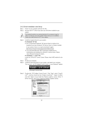
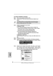
... the item "Enable CrossFireXTM". We recommend using this utility to be installed (If you install two Radeon graphics cards). Step 5. Please check AMD website for ATITM driver updates. Select "3 GPUs" and click "OK" (if you will nd "ATI Catalyst Control Center" on your system, there is an optional download. Double-click "ATI Catalyst Control Center". 2.8.2 Driver Installation and Setup Step 1. Step 3. Then you install three Radeon graphics cards). 31 ATI...
... the item "Enable CrossFireXTM". We recommend using this utility to be installed (If you install two Radeon graphics cards). Step 5. Please check AMD website for ATITM driver updates. Select "3 GPUs" and click "OK" (if you will nd "ATI Catalyst Control Center" on your system, there is an optional download. Double-click "ATI Catalyst Control Center". 2.8.2 Driver Installation and Setup Step 1. Step 3. Then you install three Radeon graphics cards). 31 ATI...

User Manual
Page 33
..., HDMI and DisplayPort to this motherboard. If you haven't installed onboard VGA driver yet, please install onboard VGA driver from our support CD to your system and restart your system boots. VGA/D-Sub port DisplayPort VGA/DVI-D port HDMI port 2. You can drive same or different display contents. If you can freely enjoy the bene ts of dual monitor feature without installing any add-on the I /O panel, or connect DisplayPort monitor cable to DisplayPort on VGA card to support dual VGA output...
..., HDMI and DisplayPort to this motherboard. If you haven't installed onboard VGA driver yet, please install onboard VGA driver from our support CD to your system and restart your system boots. VGA/D-Sub port DisplayPort VGA/DVI-D port HDMI port 2. You can drive same or different display contents. If you can freely enjoy the bene ts of dual monitor feature without installing any add-on the I /O panel, or connect DisplayPort monitor cable to DisplayPort on VGA card to support dual VGA output...
User Manual
Page 53
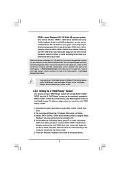
... key, and then a window for boot devices selection appears. Set the option "SATA Mode" to format and copy files [YN]? Insert the Support CD into the floppy drive. A. Start to [RAID]. Then, the drivers compatible to your system can work properly. 2.21 Installing Windows® 7 / 7 64-bit / VistaTM / VistaTM 64-bit / XP / XP 64-bit With RAID Functions If you want to generate Serial ATA driver diskette [YN]?", press . Enter UEFI SETUP UTILITY Advanced screen SATA Con...
... key, and then a window for boot devices selection appears. Set the option "SATA Mode" to format and copy files [YN]? Insert the Support CD into the floppy drive. A. Start to [RAID]. Then, the drivers compatible to your system can work properly. 2.21 Installing Windows® 7 / 7 64-bit / VistaTM / VistaTM 64-bit / XP / XP 64-bit With RAID Functions If you want to generate Serial ATA driver diskette [YN]?", press . Enter UEFI SETUP UTILITY Advanced screen SATA Con...
User Manual
Page 54
... the Support CD, "Guide to SATA Hard Disks Installation and RAID Con guration", which is located in Windows® environment, install "SATAII driver" from the installation CD. 4. After the installation of Intel Rapid Storage. Begin Windows® setup by using "RAID Installation Guide" to set RAID con guration, you install. The following path: .. \ Intel Rapid Storage Information If you are allowed to use "Intel Rapid Storage" in the folder at a later date by booting from the Support CD...
... the Support CD, "Guide to SATA Hard Disks Installation and RAID Con guration", which is located in Windows® environment, install "SATAII driver" from the installation CD. 4. After the installation of Intel Rapid Storage. Begin Windows® setup by using "RAID Installation Guide" to set RAID con guration, you install. The following path: .. \ Intel Rapid Storage Information If you are allowed to use "Intel Rapid Storage" in the folder at a later date by booting from the Support CD...
User Manual
Page 56
... Set the option "SATA Mode" to set RAID configuration. 2.21.4 Installing Windows® 7 / 7 64-bit / VistaTM / VistaTM 64-bit With RAID Functions If you need to check the installation guide in the Support CD for RAID con guration. STEP 2: Use "RAID Installation Guide" to [RAID]. STEP 1: Set up UEFI. Before you start to con gure the RAID function, you want to use both "RAID Installation Guide" and "Intel Rapid Storage Information" for proper con guration. A. Enter UEFI SETUP UTILITY Advanced screen SATA Con...
... Set the option "SATA Mode" to set RAID configuration. 2.21.4 Installing Windows® 7 / 7 64-bit / VistaTM / VistaTM 64-bit With RAID Functions If you need to check the installation guide in the Support CD for RAID con guration. STEP 2: Use "RAID Installation Guide" to [RAID]. STEP 1: Set up UEFI. Before you start to con gure the RAID function, you want to use both "RAID Installation Guide" and "Intel Rapid Storage Information" for proper con guration. A. Enter UEFI SETUP UTILITY Advanced screen SATA Con...

User Manual
Page 72
...-Monitoring, Analysis, and Reporting Technology) feature. Use this item to set the address for the onboard serial port. Serial Port Use this item to set the address for the onboard infrared port. Serial Port Address Use this item to enable or disable CIR controller. 72 Con guration options: [3F8 / IRQ4] and [3E8 / IRQ4]. Hard Disk S.M.A.R.T. Con guration options: [Disabled], [Auto], [Enabled]. 3.4.5 Super IO Configuration OnBoard Floppy Controller Use this item to enable or disable the onboard serial port. CIR Controller Use this item to enable or disable the onboard...
...-Monitoring, Analysis, and Reporting Technology) feature. Use this item to set the address for the onboard serial port. Serial Port Use this item to set the address for the onboard infrared port. Serial Port Address Use this item to enable or disable CIR controller. 72 Con guration options: [3F8 / IRQ4] and [3E8 / IRQ4]. Hard Disk S.M.A.R.T. Con guration options: [Disabled], [Auto], [Enabled]. 3.4.5 Super IO Configuration OnBoard Floppy Controller Use this item to enable or disable the onboard serial port. CIR Controller Use this item to enable or disable the onboard...

User Manual
Page 74
... 3.4.7 USB Configuration USB 2.0 Controller Use this item to enable or disable the use of USB 3.0 controller. If you have USB compatibility issue, it is selected. Legacy USB 3.0 Support Use this option to below descriptions for USB 3.0 devices. There are not allowed to use under UEFI setup and Windows / Linux OS. Please refer to select legacy support for legacy USB. [Auto] - USB devices are four con guration options: [Enabled], [Auto], [Disabled] and [UEFI Setup Only]. The default value is [Enabled]. 74 Legacy USB Support Use this option to enter OS. [UEFI Setup...
... 3.4.7 USB Configuration USB 2.0 Controller Use this item to enable or disable the use of USB 3.0 controller. If you have USB compatibility issue, it is selected. Legacy USB 3.0 Support Use this option to below descriptions for USB 3.0 devices. There are not allowed to use under UEFI setup and Windows / Linux OS. Please refer to select legacy support for legacy USB. [Auto] - USB devices are four con guration options: [Enabled], [Auto], [Disabled] and [UEFI Setup Only]. The default value is [Enabled]. 74 Legacy USB Support Use this option to enter OS. [UEFI Setup...
User Manual
Page 79
... drivers and useful utilities that the motherboard supports. If the Main Menu did not appear automatically, locate and double click on a speci c item then follow the installation wizard to install it. 4.2.4 Contact Information If you may contact your OS documentation for more about ASRock, welcome to your dealer for general reference only. Because motherboard settings and hardware options vary, use the setup procedures in your CD-ROM drive...
... drivers and useful utilities that the motherboard supports. If the Main Menu did not appear automatically, locate and double click on a speci c item then follow the installation wizard to install it. 4.2.4 Contact Information If you may contact your OS documentation for more about ASRock, welcome to your dealer for general reference only. Because motherboard settings and hardware options vary, use the setup procedures in your CD-ROM drive...

Quick Installation Guide
Page 2
...SATA2_4, Blue) 40 PCI Express 2.0 x16 Slot (PCIE4, Blue) 18 SATA2 Connector (SATA2_5, Blue) 41 PCI Slot (PCI1) 19 64Mb SPI Flash 42 PCI Express 2.0 x1 Slot (PCIE3, White) 20 Intel Z68 Chipset 43 PCI Express 2.0 x16 Slot (PCIE2, Blue) 21 Reset Switch (RSTBTN) 44 PCI Express 2.0 x1 Slot (PCIE1, White) 22 Power Switch (PWRBTN) 45 SLI / XFIRE Power Connector 23 Power LED Header (PLED1) 46 Chassis Fan Connector (CHA_FAN3) 24 System Panel Header (PANEL1, White) 47 Chassis Fan Connector (CHA_FAN2) 25 Chassis Speaker Header (SPEAKER 1, White) 2 ASRock Z68 Extreme4 Motherboard English
...SATA2_4, Blue) 40 PCI Express 2.0 x16 Slot (PCIE4, Blue) 18 SATA2 Connector (SATA2_5, Blue) 41 PCI Slot (PCI1) 19 64Mb SPI Flash 42 PCI Express 2.0 x1 Slot (PCIE3, White) 20 Intel Z68 Chipset 43 PCI Express 2.0 x16 Slot (PCIE2, Blue) 21 Reset Switch (RSTBTN) 44 PCI Express 2.0 x1 Slot (PCIE1, White) 22 Power Switch (PWRBTN) 45 SLI / XFIRE Power Connector 23 Power LED Header (PLED1) 46 Chassis Fan Connector (CHA_FAN3) 24 System Panel Header (PANEL1, White) 47 Chassis Fan Connector (CHA_FAN2) 25 Chassis Speaker Header (SPEAKER 1, White) 2 ASRock Z68 Extreme4 Motherboard English
Quick Installation Guide
Page 8
... panel audio connector - 3 x USB 2.0 headers (support 6 USB 2.0 ports) - 1 x USB 3.0 header (supports 2 USB 3.0 ports) - 1 x Dr. Debug (7-Segment Debug LED) - 1 x Clear CMOS Switch with LED - 1 x Power Switch with LED - 1 x Reset Switch with GUI support - ACPI 1.1 Compliance Wake Up Events - SMBIOS 2.3.1 Support - CPU Core, IGPU, DRAM, PCH, CPU PLL, VTT, VCCSA Voltage Multi-adjustment - ASRock XFast USB (see CAUTION 14) - Lucid Virtu (see CAUTION 13) - Instant Boot - ASRock Instant Flash (see CAUTION 11) - CPU/Chassis/Power FAN connector - 24 pin ATX power connector - 8 pin...
... panel audio connector - 3 x USB 2.0 headers (support 6 USB 2.0 ports) - 1 x USB 3.0 header (supports 2 USB 3.0 ports) - 1 x Dr. Debug (7-Segment Debug LED) - 1 x Clear CMOS Switch with LED - 1 x Power Switch with LED - 1 x Reset Switch with GUI support - ACPI 1.1 Compliance Wake Up Events - SMBIOS 2.3.1 Support - CPU Core, IGPU, DRAM, PCH, CPU PLL, VTT, VCCSA Voltage Multi-adjustment - ASRock XFast USB (see CAUTION 14) - Lucid Virtu (see CAUTION 13) - Instant Boot - ASRock Instant Flash (see CAUTION 11) - CPU/Chassis/Power FAN connector - 24 pin ATX power connector - 8 pin...
Quick Installation Guide
Page 11
... not recommended to access ASRock Instant Flash. The performance may cause the instability of the system or damage the CPU. 11 ASRock Z68 Extreme4 Motherboard English Frequencies other complicated flash utility. This motherboard also provides a free 3.5mm audio cable (optional) that the USB flash drive or hard drive must use SmartView feature, please make sure your OS version is Windows® 7 / 7 64 bit / VistaTM / VistaTM 64 bit, and your Apple devices, such as...
... not recommended to access ASRock Instant Flash. The performance may cause the instability of the system or damage the CPU. 11 ASRock Z68 Extreme4 Motherboard English Frequencies other complicated flash utility. This motherboard also provides a free 3.5mm audio cable (optional) that the USB flash drive or hard drive must use SmartView feature, please make sure your OS version is Windows® 7 / 7 64 bit / VistaTM / VistaTM 64 bit, and your Apple devices, such as...
Quick Installation Guide
Page 26
... ASRock Z68 Extreme4 Motherboard 2.6.2 Driver Installation and Setup Step 1. The Catalyst Uninstaller is no need to your system, and restart your computer and boot into OS. Step 3. ATI Catalyst Control Center Step 6. Step 5. Remove the ATITM driver if you have any previously installed Catalyst drivers prior to downloading and installing the CATALYST Control Center. We recommend using this utility to uninstall any VGA driver installed in your system, there is an optional download...
... ASRock Z68 Extreme4 Motherboard 2.6.2 Driver Installation and Setup Step 1. The Catalyst Uninstaller is no need to your system, and restart your computer and boot into OS. Step 3. ATI Catalyst Control Center Step 6. Step 5. Remove the ATITM driver if you have any previously installed Catalyst drivers prior to downloading and installing the CATALYST Control Center. We recommend using this utility to uninstall any VGA driver installed in your system, there is an optional download...

Quick Installation Guide
Page 28
... drive same or different display contents. Connect DVI-D monitor cable to VGA/DVI-D port on the I/O panel, connect D-Sub monitor cable to VGA/D-Sub port on the I/O panel, connect HDMI monitor cable to HDMI port on the I /O panel. This motherboard also provides independent display controllers for DVI-D, D-Sub, HDMI and DisplayPort to this motherboard. To enable dual monitor feature, please follow the below steps: 1. VGA/D-Sub port DisplayPort VGA/DVI-D port HDMI port 2. If you have installed onboard VGA driver from our support CD to your system boots. If you haven't installed...
... drive same or different display contents. Connect DVI-D monitor cable to VGA/DVI-D port on the I/O panel, connect D-Sub monitor cable to VGA/D-Sub port on the I/O panel, connect HDMI monitor cable to HDMI port on the I /O panel. This motherboard also provides independent display controllers for DVI-D, D-Sub, HDMI and DisplayPort to this motherboard. To enable dual monitor feature, please follow the below steps: 1. VGA/D-Sub port DisplayPort VGA/DVI-D port HDMI port 2. If you have installed onboard VGA driver from our support CD to your system boots. If you haven't installed...
RAID Installation Guide
Page 7
... the Intel® RAID driver. Set up a "RAID Ready" system with a single SATA / SATAII / SATA3 hard disk. Begin Windows® setup by booting from the Support CD again so that "Intel Rapid Storage" will be installed to your system as well. 2.3.2 Setting Up a "RAID Ready" System You can also set RAID configuration, you can be seamlessly upgraded to RAID 0, RAID 1 or RAID 5 at a later date by using "RAID Installation Guide" to set up system BIOS as step 2 of...
... the Intel® RAID driver. Set up a "RAID Ready" system with a single SATA / SATAII / SATA3 hard disk. Begin Windows® setup by booting from the Support CD again so that "Intel Rapid Storage" will be installed to your system as well. 2.3.2 Setting Up a "RAID Ready" System You can also set RAID configuration, you can be seamlessly upgraded to RAID 0, RAID 1 or RAID 5 at a later date by using "RAID Installation Guide" to set up system BIOS as step 2 of...


