
User Manual
Page 3
... Dr. Debug 40 2.14 HDMI_SPDIF Header Connection Guide 43 2.15 Serial ATA (SATA) / Serial ATAII (SATAII) Hard Disks Installation 44 2.16 Serial ATA3 (SATA3) Hard Disks Installation 44 2.17 Hot Plug and Hot Swap Functions for SATA / SATAII HDDs 45 2.18 Hot Plug and Hot Swap Functions for... SATA3 HDDs .... 45 2.19 SATA / SATAII / SATA3 HDD Hot Plug Feature and Operation Guide 46 2.20 Driver Installation Guide 48 2.21 Installing Windows® 7 / 7 64-bit / VistaTM /...
... Dr. Debug 40 2.14 HDMI_SPDIF Header Connection Guide 43 2.15 Serial ATA (SATA) / Serial ATAII (SATAII) Hard Disks Installation 44 2.16 Serial ATA3 (SATA3) Hard Disks Installation 44 2.17 Hot Plug and Hot Swap Functions for SATA / SATAII HDDs 45 2.18 Hot Plug and Hot Swap Functions for... SATA3 HDDs .... 45 2.19 SATA / SATAII / SATA3 HDD Hot Plug Feature and Operation Guide 46 2.20 Driver Installation Guide 48 2.21 Installing Windows® 7 / 7 64-bit / VistaTM /...
User Manual
Page 7
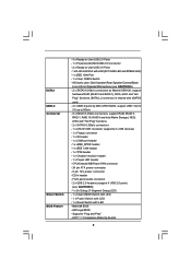
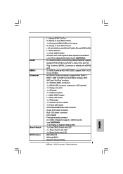
... Wake Up Events 7 Front panel audio connector - 2 x USB 2.0 headers (support 4 USB 2.0 ports) (see CAUTION 5) - 2 x SATA3 6.0Gb/s connectors by Marvell SE9128, support hardware RAID (RAID 0 and RAID 1), NCQ, AHCI and "Hot Plug" functions (SATA3_2 connector is shared...Ready-to 5Gb/s - 6 x SATAII 3.0Gb/s connectors, support RAID (RAID 0, RAID 1, RAID 10, RAID 5 and Intel Matrix Storage), NCQ, AHCI and "Hot Plug" functions - 2 x SATA3 6.0Gb/s connectors - 1 x ATA133 IDE connector (supports 2 x IDE devices) - 1 x Floppy connector - 1 x IR header - 1 x COM port header - 1 x HDMI_SPDIF header ...
... Wake Up Events 7 Front panel audio connector - 2 x USB 2.0 headers (support 4 USB 2.0 ports) (see CAUTION 5) - 2 x SATA3 6.0Gb/s connectors by Marvell SE9128, support hardware RAID (RAID 0 and RAID 1), NCQ, AHCI and "Hot Plug" functions (SATA3_2 connector is shared...Ready-to 5Gb/s - 6 x SATAII 3.0Gb/s connectors, support RAID (RAID 0, RAID 1, RAID 10, RAID 5 and Intel Matrix Storage), NCQ, AHCI and "Hot Plug" functions - 2 x SATA3 6.0Gb/s connectors - 1 x ATA133 IDE connector (supports 2 x IDE devices) - 1 x Floppy connector - 1 x IR header - 1 x COM port header - 1 x HDMI_SPDIF header ...
User Manual
Page 13
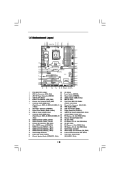
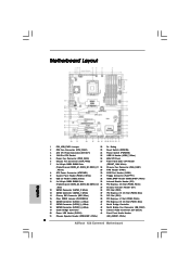
...: DDR3_A2, DDR3_B2, DDR3_C2 34 PCI Express x16 Slot (PCIE4, White) ; Blue) 35 Chassis Intrusion Header (CI1) 12 SATA3 Connector (SATA3_2, White) 36 PCI Slot (PCI2) 13 SATA3 Connector (SATA3_1, White) 37 PCI Express 2.0 x16 Slot (PCIE3, Blue) 14 Primary IDE Connector (IDE1, Blue) 38 ... SATA3_1 Designed in Taipei LAN PHY AUDIO CODEC Super I/O CI1 1 IR1 1 HDMI_SPDIF1 1 FLOPPY1 NEC USB 3.0 SATA3 6Gb/s IDE1 PCIE1 QPI 6.4GT/s PCIE2 PCI Express 2.0 PCI1 X58 Extreme3 8Mb BIOS 1394a CMOS Battery CLRCMOS1 1 PCIE3 ErP/EuP Ready PCI2 VIA VT6308S Intel ICH10R RoHS PCIE4 COM1 1...
...: DDR3_A2, DDR3_B2, DDR3_C2 34 PCI Express x16 Slot (PCIE4, White) ; Blue) 35 Chassis Intrusion Header (CI1) 12 SATA3 Connector (SATA3_2, White) 36 PCI Slot (PCI2) 13 SATA3 Connector (SATA3_1, White) 37 PCI Express 2.0 x16 Slot (PCIE3, Blue) 14 Primary IDE Connector (IDE1, Blue) 38 ... SATA3_1 Designed in Taipei LAN PHY AUDIO CODEC Super I/O CI1 1 IR1 1 HDMI_SPDIF1 1 FLOPPY1 NEC USB 3.0 SATA3 6Gb/s IDE1 PCIE1 QPI 6.4GT/s PCIE2 PCI Express 2.0 PCI1 X58 Extreme3 8Mb BIOS 1394a CMOS Battery CLRCMOS1 1 PCIE3 ErP/EuP Ready PCI2 VIA VT6308S Intel ICH10R RoHS PCIE4 COM1 1...

User Manual
Page 33
Primary IDE connector (Blue) (39-pin IDE1, see p.13 No. 31) Pin1 FLOPPY1 the red-striped side to the instruction of the motherboard! The current SATA3 interface allows up to 6.0 Gb/s data transfer rate. 33 Do NOT place jumper caps over the headers and connectors will cause permanent damage of your ... devices. Serial ATAII Connectors (SATAII_1_2: see p.13, No. 16) (SATAII_3_4: see p.13, No. 17) (SATAII_5_6: see p.13, No. 12) SATA3_2 SATA3_1 These two Serial ATA3 (SATA3) connectors support SATA data cables for internal storage devices.
Primary IDE connector (Blue) (39-pin IDE1, see p.13 No. 31) Pin1 FLOPPY1 the red-striped side to the instruction of the motherboard! The current SATA3 interface allows up to 6.0 Gb/s data transfer rate. 33 Do NOT place jumper caps over the headers and connectors will cause permanent damage of your ... devices. Serial ATAII Connectors (SATAII_1_2: see p.13, No. 16) (SATAII_3_4: see p.13, No. 17) (SATAII_5_6: see p.13, No. 12) SATA3_2 SATA3_1 These two Serial ATA3 (SATA3) connectors support SATA data cables for internal storage devices.

User Manual
Page 34
... certificates, passwords, and data. Then connect the white end of SATA power cable to the power connector of SATA power cable to the SATA / SATAII / SATA3 hard disk or the SATAII / SATA3 connector on this motherboard. This header supports an optional wireless transmitting and receiving infrared module. 34
... certificates, passwords, and data. Then connect the white end of SATA power cable to the power connector of SATA power cable to the SATA / SATAII / SATA3 hard disk or the SATAII / SATA3 connector on this motherboard. This header supports an optional wireless transmitting and receiving infrared module. 34

User Manual
Page 44
... Matrix Storage function, you need to switch the "Configure SATAII as" setting between AHCI and IDE mode after OS installation. 2.16 Serial ATA3 (SATA3) Hard Disks Installation This motherboard adopts Marvell SE9128 chipset that supports Serial ATA (SATA) / Serial ATAII (SATAII) hard disks and RAID (RAID... may install SATA / SATAII hard disks on this motherboard for internal storage devices. This section will guide you to the motherboard's SATA3 connector. It is not recommended to install at least 3 SATA / SATAII hard disks. 2. STEP 3: Connect one end of your chassis. STEP ...
... Matrix Storage function, you need to switch the "Configure SATAII as" setting between AHCI and IDE mode after OS installation. 2.16 Serial ATA3 (SATA3) Hard Disks Installation This motherboard adopts Marvell SE9128 chipset that supports Serial ATA (SATA) / Serial ATAII (SATAII) hard disks and RAID (RAID... may install SATA / SATAII hard disks on this motherboard for internal storage devices. This section will guide you to the motherboard's SATA3 connector. It is not recommended to install at least 3 SATA / SATAII hard disks. 2. STEP 3: Connect one end of your chassis. STEP ...

User Manual
Page 45
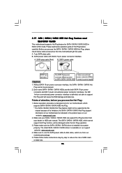
..., please note that it is called "Hot Swap" for RAID configuration, it cannot perform Hot Plug if the OS has been installed into the SATA3 HDD. If SATA3 HDDs are NOT set for the action to insert and remove the SATA / SATAII HDDs while the system is still power-on and in... power-on and in working condition. If SATA / SATAII HDDs are NOT set for RAID configuration, it is called "Hot Plug" for SATA3 in working condition. 45 If the SATA3 HDDs are built as RAID1 then it cannot perform Hot Plug if the OS has been installed into the SATA / SATAII HDD...
..., please note that it is called "Hot Swap" for RAID configuration, it cannot perform Hot Plug if the OS has been installed into the SATA3 HDD. If SATA3 HDDs are NOT set for the action to insert and remove the SATA / SATAII HDDs while the system is still power-on and in... power-on and in working condition. If SATA / SATAII HDDs are NOT set for RAID configuration, it is called "Hot Plug" for SATA3 in working condition. 45 If the SATA3 HDDs are built as RAID1 then it cannot perform Hot Plug if the OS has been installed into the SATA / SATAII HDD...
User Manual
Page 46
... cause the HDD damage and data loss. Please make sure the SATA / SATAII / SATA3 driver is designed only for SATA / SATAII / SATA3 HDD in the product spec on our support website: www.asrock.com 4. Please follow below instructions step by the chipset because of its limitation, the SATA... / SATAII / SATA3 Hot Plug support information of our motherboard is available on our website: www.asrock.com 2. 2.19 SATA / SATAII / SATA3 HDD Hot Plug Feature and Operation Guide This motherboard supports Hot Plug feature for our ...
... cause the HDD damage and data loss. Please make sure the SATA / SATAII / SATA3 driver is designed only for SATA / SATAII / SATA3 HDD in the product spec on our support website: www.asrock.com 4. Please follow below instructions step by the chipset because of its limitation, the SATA... / SATAII / SATA3 Hot Plug support information of our motherboard is available on our website: www.asrock.com 2. 2.19 SATA / SATAII / SATA3 HDD Hot Plug Feature and Operation Guide This motherboard supports Hot Plug feature for our ...

User Manual
Page 47
... before you process the Hot Unplug: Please do follow below instruction sequence to SATA / SATAII / SATA3 HDD. the motherboard's SATAII / SATA3 connector. How to Hot Unplug a SATA / SATAII / SATA3 HDD: Points of attention, before you process the Hot Plug: Please do follow below instruction sequence ...to process the Hot Unplug, improper procedure will cause the SATA / SATAII / SATA3 HDD damage and data loss. Step 1 Unplug SATA data cable from SATA / SATAII / SATA3 HDD side. 47 SATA power cable 1x4-pin power connector (White) Step 3 Connect SATA ...
... before you process the Hot Unplug: Please do follow below instruction sequence to SATA / SATAII / SATA3 HDD. the motherboard's SATAII / SATA3 connector. How to Hot Unplug a SATA / SATAII / SATA3 HDD: Points of attention, before you process the Hot Plug: Please do follow below instruction sequence ...to process the Hot Unplug, improper procedure will cause the SATA / SATAII / SATA3 HDD damage and data loss. Step 1 Unplug SATA data cable from SATA / SATAII / SATA3 HDD side. 47 SATA power cable 1x4-pin power connector (White) Step 3 Connect SATA ...

User Manual
Page 66
...default value is [IDE]. Configuration mode: [IDE] and [AHCI]. Then in the option "Configure SATAII as [IDE] Marvell SATA3 RAID Mode Setup Marvell SATA3 Configuration [Enabled] Marvell SATA3 Operation Mode [IDE] Compatible Mode [Auto] SATAII 1 SATAII 2 SATAII 3 SATAII 4 SATAII 5 SATAII 6 Marvell SATA3_1 Marvell... Storage Configuration SATAII Configuration [Enhanced] Configure SATAII as ", you are allowed to set the selection to build RAID for Marvell SATA3 ports. SATAII Configuration Please select [Compatible] when you select [RAID] or [AHCI] mode, the options "Hot Plug" ...
...default value is [IDE]. Configuration mode: [IDE] and [AHCI]. Then in the option "Configure SATAII as [IDE] Marvell SATA3 RAID Mode Setup Marvell SATA3 Configuration [Enabled] Marvell SATA3 Operation Mode [IDE] Compatible Mode [Auto] SATAII 1 SATAII 2 SATAII 3 SATAII 4 SATAII 5 SATAII 6 Marvell SATA3_1 Marvell... Storage Configuration SATAII Configuration [Enhanced] Configure SATAII as ", you are allowed to set the selection to build RAID for Marvell SATA3 ports. SATAII Configuration Please select [Compatible] when you select [RAID] or [AHCI] mode, the options "Hot Plug" ...
Quick Installation Guide
Page 2
...Triple Channel: DDR3_A1, DDR3_B1, DDR3_C1 28 Chassis Fan Connector (CHA_FAN1) ; Blue) 35 Chassis Intrusion Header (CI1) 12 SATA3 Connector (SATA3_2, White) 36 PCI Slot (PCI2) 13 SATA3 Connector (SATA3_1, White) 37 PCI Express 2.0 x16 Slot (PCIE3, Blue) 14 Primary IDE Connector (IDE1, Blue)...CD1 (Black) 20 Power LED Header (PLED1) 44 Front Panel Audio Header 21 Chassis Speaker Header (SPEAKER 1, White) (HD_AUDIO1, White) 2 ASRock X58 Extreme3 Motherboard English White) 29 TPM Header (TPM1) 8 ATX Power Connector (ATXPWR1) 30 COM Port Header (COM1) 9 System Panel Header (PANEL1,...
...Triple Channel: DDR3_A1, DDR3_B1, DDR3_C1 28 Chassis Fan Connector (CHA_FAN1) ; Blue) 35 Chassis Intrusion Header (CI1) 12 SATA3 Connector (SATA3_2, White) 36 PCI Slot (PCI2) 13 SATA3 Connector (SATA3_1, White) 37 PCI Express 2.0 x16 Slot (PCIE3, Blue) 14 Primary IDE Connector (IDE1, Blue)...CD1 (Black) 20 Power LED Header (PLED1) 44 Front Panel Audio Header 21 Chassis Speaker Header (SPEAKER 1, White) (HD_AUDIO1, White) 2 ASRock X58 Extreme3 Motherboard English White) 29 TPM Header (TPM1) 8 ATX Power Connector (ATXPWR1) 30 COM Port Header (COM1) 9 System Panel Header (PANEL1,...
Quick Installation Guide
Page 7
... audio connector - 2 x USB 2.0 headers (support 4 USB 2.0 ports) (see CAUTION 5) - 2 x SATA3 6.0Gb/s connectors by Marvell SE9128, support hardware RAID (RAID 0 and RAID 1), NCQ, AHCI and "Hot Plug...SATA3 6.0Gb/s connectors - 1 x ATA133 IDE connector (supports 2 x IDE devices) - 1 x Floppy connector - 1 x IR header - 1 x COM port header - 1 x HDMI_SPDIF header - 1 x IEEE 1394 header - 1 x TPM header - 1 x Chassis Intrusion header - 1 x Power LED header - CPU/Chassis/NB/Power FAN connector - 24 pin ATX power connector - 8 pin 12V power connector - Supports "Plug and Play" 7 ASRock X58 Extreme3...
... audio connector - 2 x USB 2.0 headers (support 4 USB 2.0 ports) (see CAUTION 5) - 2 x SATA3 6.0Gb/s connectors by Marvell SE9128, support hardware RAID (RAID 0 and RAID 1), NCQ, AHCI and "Hot Plug...SATA3 6.0Gb/s connectors - 1 x ATA133 IDE connector (supports 2 x IDE devices) - 1 x Floppy connector - 1 x IR header - 1 x COM port header - 1 x HDMI_SPDIF header - 1 x IEEE 1394 header - 1 x TPM header - 1 x Chassis Intrusion header - 1 x Power LED header - CPU/Chassis/NB/Power FAN connector - 24 pin ATX power connector - 8 pin 12V power connector - Supports "Plug and Play" 7 ASRock X58 Extreme3...

Quick Installation Guide
Page 27
The current SATA3 interface allows up to 6.0 Gb/s data transfer rate. 27 ASRock X58 Extreme3 Motherboard Placing jumper caps over these headers and connectors. The current SATAII interface allows up to 3.0 Gb/s data transfer rate. 2.9 Onboard... Headers and Connectors Onboard headers and connectors are NOT jumpers. FDD connector (33-pin FLOPPY1) (see p.2, No. 12) SATA3_2 SATA3_1 These two Serial ATA3 (SATA3) ...
The current SATA3 interface allows up to 6.0 Gb/s data transfer rate. 27 ASRock X58 Extreme3 Motherboard Placing jumper caps over these headers and connectors. The current SATAII interface allows up to 3.0 Gb/s data transfer rate. 2.9 Onboard... Headers and Connectors Onboard headers and connectors are NOT jumpers. FDD connector (33-pin FLOPPY1) (see p.2, No. 12) SATA3_2 SATA3_1 These two Serial ATA3 (SATA3) ...

Marvell SATA3 RAID Installation Guide
Page 1
... or more physical disk drives in combination in parallel to achieve increased disk fault tolerance and improved performance. Two disks mirrored to each other. 1 Marvell SATA3 RAID Installation Guide Overview The Marvell RAID Utility (MRU) is a browser-based graphical user interface (GUI) tool for the Marvell RAID adapter. It supports IO...
... or more physical disk drives in combination in parallel to achieve increased disk fault tolerance and improved performance. Two disks mirrored to each other. 1 Marvell SATA3 RAID Installation Guide Overview The Marvell RAID Utility (MRU) is a browser-based graphical user interface (GUI) tool for the Marvell RAID adapter. It supports IO...

Marvell SATA3 RAID Installation Guide
Page 2
The system will start to the optical drive. Click "Install all" or "Marvell SATA3 Driver". Click "Next" at the welcome screen. 2 Installation Insert ASRock support CD to auto-install Marvell SATA3 driver.
The system will start to the optical drive. Click "Install all" or "Marvell SATA3 Driver". Click "Next" at the welcome screen. 2 Installation Insert ASRock support CD to auto-install Marvell SATA3 driver.

Marvell SATA3 RAID Installation Guide
Page 12
In Marvell BIOS Setup screen, select free disks to create array and continue to enter Marvell BIOS Setup screen. Press . 12 First of all, you can also use Marvell RAID ROM to configure RAID functions. Press + during the POST to create virtual disk on this array. Marvell RAID ROM Besides Marvell SATA3 RAID utility, you need to make a SATA3 driver diskette.
In Marvell BIOS Setup screen, select free disks to create array and continue to enter Marvell BIOS Setup screen. Press . 12 First of all, you can also use Marvell RAID ROM to configure RAID functions. Press + during the POST to create virtual disk on this array. Marvell RAID ROM Besides Marvell SATA3 RAID utility, you need to make a SATA3 driver diskette.