
Quick Installation Guide
Page 1
.... With respect to the contents of this documentation may apply, see www.dtsc.ca.gov/hazardouswaste/ perchlorate" ASRock Website: http://www.asrock.com When you discard the Lithium battery in California, USA, please follow the related regulations in Perchlorate Best ...Management Practices (BMP) regulations passed by ASRock. Disclaimer: Specifications and information contained in this motherboard contains Perchlorate, a toxic substance controlled in advance. This device complies with Part 15 of the ...
.... With respect to the contents of this documentation may apply, see www.dtsc.ca.gov/hazardouswaste/ perchlorate" ASRock Website: http://www.asrock.com When you discard the Lithium battery in California, USA, please follow the related regulations in Perchlorate Best ...Management Practices (BMP) regulations passed by ASRock. Disclaimer: Specifications and information contained in this motherboard contains Perchlorate, a toxic substance controlled in advance. This device complies with Part 15 of the ...
Quick Installation Guide
Page 4
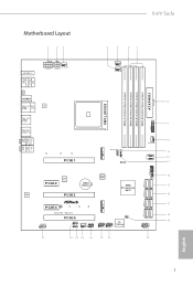
Motherboard Layout 1 23 X470 Taichi 4 5 67 M2_WIFI_1 ATX12V1 CHA_FAN3/WP ATX12V2 CPU_FAN1 CPU_FAN2/WP PS2 Keyboard /Mouse USB 3.1 Gen1 T: USB1 B: USB2 SOCKET AM4 CLRC BTN1 HDMI1 USB 3.1 Gen1 Top: T: USB3 ... module) DDR4_B1 (64 bit, 288-pin module) DDR4_B2 (64 bit, 288-pin module) SATA3_1_2 USB3_9_10 ATXPWR1 USB3_7_8 1 CHA_FAN1/WP F_USB31_TC_1 1 SATA3_3_4 SATA3_5_6 M2_2 PCIE4 HD_AUDIO1 1 X470 Taichi PCIE5 ADDR_LED1 1 RGB_LED1 1 CHA_FAN2/WP SPK_PLED1 1 USB_3_4 USB_1_2 1 1 CLRMOS1 1 Dr. Debug 27 26 25 24 23 22 21 SATA3_A1_A2 PLED PWRBTN 1 HDLED RESET PANEL1 20...
Motherboard Layout 1 23 X470 Taichi 4 5 67 M2_WIFI_1 ATX12V1 CHA_FAN3/WP ATX12V2 CPU_FAN1 CPU_FAN2/WP PS2 Keyboard /Mouse USB 3.1 Gen1 T: USB1 B: USB2 SOCKET AM4 CLRC BTN1 HDMI1 USB 3.1 Gen1 Top: T: USB3 ... module) DDR4_B1 (64 bit, 288-pin module) DDR4_B2 (64 bit, 288-pin module) SATA3_1_2 USB3_9_10 ATXPWR1 USB3_7_8 1 CHA_FAN1/WP F_USB31_TC_1 1 SATA3_3_4 SATA3_5_6 M2_2 PCIE4 HD_AUDIO1 1 X470 Taichi PCIE5 ADDR_LED1 1 RGB_LED1 1 CHA_FAN2/WP SPK_PLED1 1 USB_3_4 USB_1_2 1 1 CLRMOS1 1 Dr. Debug 27 26 25 24 23 22 21 SATA3_A1_A2 PLED PWRBTN 1 HDLED RESET PANEL1 20...
Quick Installation Guide
Page 8
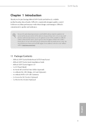
...://www.asrock.com. 1.1 Package Contents • ASRock X470 Taichi Motherboard (ATX Form Factor) • ASRock X470 Taichi Quick Installation Guide • ASRock X470 Taichi Support CD • 1 x I/O Panel Shield • 4 x Serial ATA (SATA) Data Cables (Optional) • 1 x ASRock SLI_HB_Bridge_2S Card (Optional) • 2 x ASRock WiFi 2.4/5 GHz Antennas • 2 x Screws for M.2 Socket (Optional) • 1 x Nut for purchasing ASRock X470 Taichi motherboard, a reliable motherboard produced under ASRock's consistently stringent quality control. X470 Taichi Chapter...
...://www.asrock.com. 1.1 Package Contents • ASRock X470 Taichi Motherboard (ATX Form Factor) • ASRock X470 Taichi Quick Installation Guide • ASRock X470 Taichi Support CD • 1 x I/O Panel Shield • 4 x Serial ATA (SATA) Data Cables (Optional) • 1 x ASRock SLI_HB_Bridge_2S Card (Optional) • 2 x ASRock WiFi 2.4/5 GHz Antennas • 2 x Screws for M.2 Socket (Optional) • 1 x Nut for purchasing ASRock X470 Taichi motherboard, a reliable motherboard produced under ASRock's consistently stringent quality control. X470 Taichi Chapter...

Quick Installation Guide
Page 15
... and ensures extraordinary low power consumption for WiFi 802.11 a/b/ g/n/ac connectivity standards and Bluetooth v4.2. 1.3 WiFi-802.11ac Module and ASRock WiFi 2.4/5 GHz Antenna WiFi-802.11ac + BT Module This motherboard comes with an exclusive WiFi 802.11 a/b/g/n/ac + BT v4.2 module (pre-installed on the rear I/O panel) that adds a whole...
... and ensures extraordinary low power consumption for WiFi 802.11 a/b/ g/n/ac connectivity standards and Bluetooth v4.2. 1.3 WiFi-802.11ac Module and ASRock WiFi 2.4/5 GHz Antenna WiFi-802.11ac + BT Module This motherboard comes with an exclusive WiFi 802.11 a/b/g/n/ac + BT v4.2 module (pre-installed on the rear I/O panel) that adds a whole...

Quick Installation Guide
Page 17
...components, place them on a carpet. Doing so may cause physical injuries to you and damages to motherboard components. • In order to avoid damage from static electricity to the motherboard's components, NEVER place your chassis to ensure that comes with the components. • When placing ...screws to secure the motherboard to the chassis, please do not touch the ICs. • Whenever you uninstall any motherboard settings. • Make sure to use a grounded wrist strap or touch a safety grounded object...
...components, place them on a carpet. Doing so may cause physical injuries to you and damages to motherboard components. • In order to avoid damage from static electricity to the motherboard's components, NEVER place your chassis to ensure that comes with the components. • When placing ...screws to secure the motherboard to the chassis, please do not touch the ICs. • Whenever you uninstall any motherboard settings. • Make sure to use a grounded wrist strap or touch a safety grounded object...

Quick Installation Guide
Page 20
X470 Taichi 2.2 Installing the CPU Fan and Heatsink After you install the CPU into this motherboard, it is necessary to install a larger heatsink and cooling fan to improve heat dissipation. Please turn off the power or remove the power cord before changing a CPU or heatsink. Installing the CPU Box Cooler SR1 1 2 17 English Make sure that the CPU and the heatsink are securely fastened and in good contact with each other. You also need to spray thermal grease between the CPU and the heatsink to dissipate heat.
X470 Taichi 2.2 Installing the CPU Fan and Heatsink After you install the CPU into this motherboard, it is necessary to install a larger heatsink and cooling fan to improve heat dissipation. Please turn off the power or remove the power cord before changing a CPU or heatsink. Installing the CPU Box Cooler SR1 1 2 17 English Make sure that the CPU and the heatsink are securely fastened and in good contact with each other. You also need to spray thermal grease between the CPU and the heatsink to dissipate heat.

Quick Installation Guide
Page 29
...(Mhz) 2933 2400 2933 2400 2133 1866 Ryzen Series CPUs (Summit Ridge) UDIMM Memory Slot A1 A2 B1 B2 - SR - - - otherwise, this motherboard and DIMM may be damaged. DDR4 UDIMM Maximum Frequency Support Ryzen Series CPUs (Pinnacle Ridge): UDIMM Memory Slot A1 A2 B1 B2 - SR - - -.../DR DR Frequency (Mhz) 2667 2667 2667 2400-2667 2133-2400 1866-2133 26 English SR - 2.3 Installing Memory Modules (DIMM) This motherboard provides four 288-pin DDR4 (Double Data Rate 4) DIMM slots, and supports Dual Channel Memory Technology. 1. DR - - - DR - - - SR -...
...(Mhz) 2933 2400 2933 2400 2133 1866 Ryzen Series CPUs (Summit Ridge) UDIMM Memory Slot A1 A2 B1 B2 - SR - - - otherwise, this motherboard and DIMM may be damaged. DDR4 UDIMM Maximum Frequency Support Ryzen Series CPUs (Pinnacle Ridge): UDIMM Memory Slot A1 A2 B1 B2 - SR - - -.../DR DR Frequency (Mhz) 2667 2667 2667 2400-2667 2133-2400 1866-2133 26 English SR - 2.3 Installing Memory Modules (DIMM) This motherboard provides four 288-pin DDR4 (Double Data Rate 4) DIMM slots, and supports Dual Channel Memory Technology. 1. DR - - - DR - - - SR -...

Quick Installation Guide
Page 31
It will cause permanent damage to the motherboard and the DIMM if you force the DIMM into the slot at incorrect orientation. 1 2 3 28 English The DIMM only fits in one correct orientation.
It will cause permanent damage to the motherboard and the DIMM if you force the DIMM into the slot at incorrect orientation. 1 2 3 28 English The DIMM only fits in one correct orientation.

Quick Installation Guide
Page 32
PCIE2 (PCIe 2.0 x1 slot) is used for PCI Express x16 lane width graphics cards. English 29 X470 Taichi 2.4 Expansion Slots (PCI Express Slots) There are 5 PCI Express slots on the motherboard. PCIE4 (PCIe 2.0 x1 slot) is used for PCI Express x1 lane width cards. PCIe slots: PCIE1 (PCIe...Graphics Cards in CrossFireXTM or SLITM Mode PCIE1 x16 x8 PCIE3 N/A x8 For a better thermal environment, please connect a chassis fan to the motherboard's chassis fan connector (CHA_FAN1/WP, CHA_FAN2/WP or CHA_FAN3/WP ) when using multiple graphics cards. PCIE3 (PCIe 3.0 x16 slot) is ...
PCIE2 (PCIe 2.0 x1 slot) is used for PCI Express x16 lane width graphics cards. English 29 X470 Taichi 2.4 Expansion Slots (PCI Express Slots) There are 5 PCI Express slots on the motherboard. PCIE4 (PCIe 2.0 x1 slot) is used for PCI Express x1 lane width cards. PCIe slots: PCIE1 (PCIe...Graphics Cards in CrossFireXTM or SLITM Mode PCIE1 x16 x8 PCIE3 N/A x8 For a better thermal environment, please connect a chassis fan to the motherboard's chassis fan connector (CHA_FAN1/WP, CHA_FAN2/WP or CHA_FAN3/WP ) when using multiple graphics cards. PCIE3 (PCIe 3.0 x16 slot) is ...

Quick Installation Guide
Page 34
... jumper caps over the headers and connectors will cause permanent damage to turn off (S5). The front panel design may configure the way to the motherboard. Note the positive and negative pins before connecting the cables. RESET (Reset Button): Connect to the hard drive activity LED on the chassis front panel...) (see p.1, No. 20) PLED+ PLEDPWRBTN# GND 1 GND RESET# GND HDLEDHDLED+ Connect the power button, reset button and system status indicator on the chassis front panel. X470 Taichi 2.6 Onboard Headers and Connectors Onboard headers and connectors are matched correctly.
... jumper caps over the headers and connectors will cause permanent damage to turn off (S5). The front panel design may configure the way to the motherboard. Note the positive and negative pins before connecting the cables. RESET (Reset Button): Connect to the hard drive activity LED on the chassis front panel...) (see p.1, No. 20) PLED+ PLEDPWRBTN# GND 1 GND RESET# GND HDLEDHDLED+ Connect the power button, reset button and system status indicator on the chassis front panel. X470 Taichi 2.6 Onboard Headers and Connectors Onboard headers and connectors are matched correctly.
Quick Installation Guide
Page 35
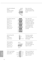
... cables for internal storage devices with up to this header. Each USB 2.0 header can support two ports. 32 English There are two headers on this motherboard. Power LED and Speaker Header (7-pin SPK_PLED1) (see p.1, No. 23) Serial ATA3 Connectors (SATA3_1_2: see p.1, No. 15) (SATA3_3_4: see p.1, No. 16) (SATA3_5_6: see p.1, No. 17...
... cables for internal storage devices with up to this header. Each USB 2.0 header can support two ports. 32 English There are two headers on this motherboard. Power LED and Speaker Header (7-pin SPK_PLED1) (see p.1, No. 23) Serial ATA3 Connectors (SATA3_1_2: see p.1, No. 15) (SATA3_3_4: see p.1, No. 16) (SATA3_5_6: see p.1, No. 17...

Quick Installation Guide
Page 36
... Jack Sensing, but the panel wire on this motherboard. Connect Mic_IN (MIC) to function correctly. GND IntA_PB_SSTX+ IntA_PB_SSTX- Front Panel Audio Header (9-pin HD_AUDIO1) (see p.1, No. 14) 1 Dummy IntA_PB_D+ IntA_PB_D- If you use an AC'97 audio panel, please install it to Ground (GND). X470 Taichi (19-pin USB3_9_10) (see p.1, No. 27) GND...
... Jack Sensing, but the panel wire on this motherboard. Connect Mic_IN (MIC) to function correctly. GND IntA_PB_SSTX+ IntA_PB_SSTX- Front Panel Audio Header (9-pin HD_AUDIO1) (see p.1, No. 14) 1 Dummy IntA_PB_D+ IntA_PB_D- If you use an AC'97 audio panel, please install it to Ground (GND). X470 Taichi (19-pin USB3_9_10) (see p.1, No. 27) GND...

Quick Installation Guide
Page 37
...3) 1 2 34 GND FAN_VOLTAGE FAN_SPEED FAN_SPEED_CONTROL CPU Fan Connector (4-pin CPU_FAN1) (see p.1, No. 24) FAN_SPEED_CONTROL CHA_FAN_SPEED FAN_VOLTAGE GND 4 This motherboard 3 2 provides three 4-Pin water 1 cooling chassis fan connectors. ATX Power Connector (24-pin ATXPWR1) (see p.1, No. 4) FAN_SPEED_CONTROL CPU_FAN_SPEED FAN_VOLTAGE GND 1...along Pin 1 and Pin 13. CPU Water Pump Fan Connector (4-pin CPU_FAN2/WP) (see p.1, No. 8) 12 24 1 13 This motherboard provides a 24-pin ATX power connector. If you plan to Pin 1-3. Chassis Water Pump Fan Connectors (4-pin CHA_FAN1/WP) (see p.1, ...
...3) 1 2 34 GND FAN_VOLTAGE FAN_SPEED FAN_SPEED_CONTROL CPU Fan Connector (4-pin CPU_FAN1) (see p.1, No. 24) FAN_SPEED_CONTROL CHA_FAN_SPEED FAN_VOLTAGE GND 4 This motherboard 3 2 provides three 4-Pin water 1 cooling chassis fan connectors. ATX Power Connector (24-pin ATXPWR1) (see p.1, No. 4) FAN_SPEED_CONTROL CPU_FAN_SPEED FAN_VOLTAGE GND 1...along Pin 1 and Pin 13. CPU Water Pump Fan Connector (4-pin CPU_FAN2/WP) (see p.1, No. 8) 12 24 1 13 This motherboard provides a 24-pin ATX power connector. If you plan to Pin 1-3. Chassis Water Pump Fan Connectors (4-pin CHA_FAN1/WP) (see p.1, ...
Quick Installation Guide
Page 38
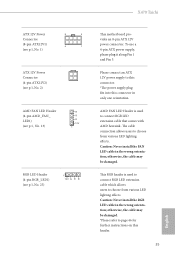
... on this connector in the wrong orientation; X470 Taichi ATX 12V Power Connector (8-pin ATX12V1) (see p.1, No. 1) 8 5 4 1 ATX 12V Power Connector (4-pin ATX12V2) (see p.1, No. 2) AMD FAN LED Header (4-pin AMD_FAN_ LED1) (see p.1, No. 13) B R G 12V 1 RGB LED Header (4-pin RGB_LED1) (see p.1, No. 25) 1 12V G R B This motherboard provides an 8-pin ATX 12V power...
... on this connector in the wrong orientation; X470 Taichi ATX 12V Power Connector (8-pin ATX12V1) (see p.1, No. 1) 8 5 4 1 ATX 12V Power Connector (4-pin ATX12V2) (see p.1, No. 2) AMD FAN LED Header (4-pin AMD_FAN_ LED1) (see p.1, No. 13) B R G 12V 1 RGB LED Header (4-pin RGB_LED1) (see p.1, No. 25) 1 12V G R B This motherboard provides an 8-pin ATX 12V power...

Quick Installation Guide
Page 40
This function is workable only when you power off your computer and unplug the power supply. English 37 X470 Taichi 2.7 Smart Switch The motherboard has one smart switch: Clear CMOS Button, allowing users to quickly clear the CMOS values. Clear CMOS Button (CLRCBTN1) (see p.3, No. 14) Clear CMOS Button allows users to clear the CMOS values.
This function is workable only when you power off your computer and unplug the power supply. English 37 X470 Taichi 2.7 Smart Switch The motherboard has one smart switch: Clear CMOS Button, allowing users to quickly clear the CMOS values. Clear CMOS Button (CLRCBTN1) (see p.3, No. 14) Clear CMOS Button allows users to clear the CMOS values.

Quick Installation Guide
Page 47
... desired nut location on the module type and length. Step 5 Gently insert the M.2 (NGFF) SSD module into place. D C B A D C B A D C B A Step 3 Move the standoff based on the motherboard. Please be used.
... desired nut location on the module type and length. Step 5 Gently insert the M.2 (NGFF) SSD module into place. D C B A D C B A D C B A Step 3 Move the standoff based on the motherboard. Please be used.

Quick Installation Guide
Page 48
X470 Taichi 1 B 12V G R RGB_LED1 1 12V G R B 1. Before installing or removing your RGB LED cable, please power off your RGB LED strip to motherboard components. 1. The RGB LED header supports standard 5050 RGB LED strip (12V/G/R/B), with sophisticated tastes to build...RGB LED cable in the wrong orientation; otherwise, the cable may cause damages to the RGB LED Header (RGB_LED1) on the motherboard. X470 Taichi 2.11 ASRock Polychrome RGB ASRock Polychrome RGB is a lighting control utility specifically designed for unique individuals with a maximum power rating of 3A (12V) and ...
X470 Taichi 1 B 12V G R RGB_LED1 1 12V G R B 1. Before installing or removing your RGB LED cable, please power off your RGB LED strip to motherboard components. 1. The RGB LED header supports standard 5050 RGB LED strip (12V/G/R/B), with sophisticated tastes to build...RGB LED cable in the wrong orientation; otherwise, the cable may cause damages to the RGB LED Header (RGB_LED1) on the motherboard. X470 Taichi 2.11 ASRock Polychrome RGB ASRock Polychrome RGB is a lighting control utility specifically designed for unique individuals with a maximum power rating of 3A (12V) and ...

Quick Installation Guide
Page 49
... LED strip (5V/Data/ GND), with the package. 2. Before installing or removing your RGB LED cable, please power off your Addressable RGB LED strip to motherboard components. 1. ADDR_LED1 1 GND DO_ADDR VOUT 1 X470 Taichi 1. Never install the RGB LED cable in the wrong orientation;
... LED strip (5V/Data/ GND), with the package. 2. Before installing or removing your RGB LED cable, please power off your Addressable RGB LED strip to motherboard components. 1. ADDR_LED1 1 GND DO_ADDR VOUT 1 X470 Taichi 1. Never install the RGB LED cable in the wrong orientation;
Quick Installation Guide
Page 50
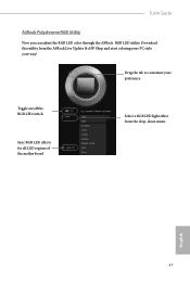
Download this utility from the drop-down menu. English 47 X470 Taichi ASRock Polychrome RGB Utility Now you can adjust the RGB LED color through the ASRock RGB LED utility. Drag the tab to customize your way! Toggle on/off the RGB LED switch Sync RGB LED effects for all LED regions of the motherboard Select a RGB LED light effect from the ASRock Live Update & APP Shop and start coloring your PC style your preference.
Download this utility from the drop-down menu. English 47 X470 Taichi ASRock Polychrome RGB Utility Now you can adjust the RGB LED color through the ASRock RGB LED utility. Drag the tab to customize your way! Toggle on/off the RGB LED switch Sync RGB LED effects for all LED regions of the motherboard Select a RGB LED light effect from the ASRock Live Update & APP Shop and start coloring your PC style your preference.

Quick Installation Guide
Page 225
... Rules. DECLARATION OF CONFORMITY Per FCC Part 2 Section 2.1077(a) Responsible Party Name: ASRock Incorporation Address: 13848 Magnolia Ave, Chino, CA91710 Phone/Fax No: +1-909-590-8308/+1-909-590-1026 hereby declares that the product Product Name : Motherboard Model Number : X470 Taichi Conforms to the following specifications: FCC Part15, SubpartB,Unintentional Radiators Supplementary...
... Rules. DECLARATION OF CONFORMITY Per FCC Part 2 Section 2.1077(a) Responsible Party Name: ASRock Incorporation Address: 13848 Magnolia Ave, Chino, CA91710 Phone/Fax No: +1-909-590-8308/+1-909-590-1026 hereby declares that the product Product Name : Motherboard Model Number : X470 Taichi Conforms to the following specifications: FCC Part15, SubpartB,Unintentional Radiators Supplementary...


