
User Manual
Page 15
... (CHA_FAN1/WP) 13 SATA3 Connectors (SATA3_5_6) 14 SATA3 Connectors (SATA3_3_4) 15 SATA3 Connectors (SATA3_1_2) 16 System Panel Header (PANEL1) 17 RGB LED Header (RGB_LED1) 18 Clear CMOS Jumper (CLRCMOS1) 19 Chassis/Water Pump Fan Connector (CHA_FAN2/WP) 20 Addressable LED Header (ADDR_LED1) 21 Chassis/Water Pump Fan Connector (CHA_FAN3/WP) 22 USB...
... (CHA_FAN1/WP) 13 SATA3 Connectors (SATA3_5_6) 14 SATA3 Connectors (SATA3_3_4) 15 SATA3 Connectors (SATA3_1_2) 16 System Panel Header (PANEL1) 17 RGB LED Header (RGB_LED1) 18 Clear CMOS Jumper (CLRCMOS1) 19 Chassis/Water Pump Fan Connector (CHA_FAN2/WP) 20 Addressable LED Header (ADDR_LED1) 21 Chassis/Water Pump Fan Connector (CHA_FAN3/WP) 22 USB...
User Manual
Page 37
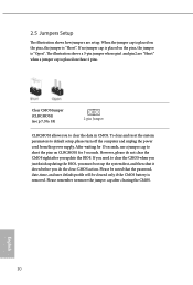
... If you to short the pins on these 2 pins. English 30 The illustration shows a 3-pin jumper whose pin1 and pin2 are setup. Clear CMOS Jumper (CLRCMOS1) (see p.7, No. 18) 2-pin Jumper CLRCMOS1 allows you need to default setup, please turn off the computer and unplug the...system first, and then shut it down before you update the BIOS. However, please do the clear-CMOS action. Please remember toremove the jumper cap after you do not clear the CMOS right after clearing the CMOS. 2.5 Jumpers Setup The illustration shows how jumpers are "Short" when a jumper cap is "Open...
... If you to short the pins on these 2 pins. English 30 The illustration shows a 3-pin jumper whose pin1 and pin2 are setup. Clear CMOS Jumper (CLRCMOS1) (see p.7, No. 18) 2-pin Jumper CLRCMOS1 allows you need to default setup, please turn off the computer and unplug the...system first, and then shut it down before you update the BIOS. However, please do the clear-CMOS action. Please remember toremove the jumper cap after you do not clear the CMOS right after clearing the CMOS. 2.5 Jumpers Setup The illustration shows how jumpers are "Short" when a jumper cap is "Open...

Quick Installation Guide
Page 6
... (CHA_FAN1/WP) 13 SATA3 Connectors (SATA3_5_6) 14 SATA3 Connectors (SATA3_3_4) 15 SATA3 Connectors (SATA3_1_2) 16 System Panel Header (PANEL1) 17 RGB LED Header (RGB_LED1) 18 Clear CMOS Jumper (CLRCMOS1) 19 Chassis/Water Pump Fan Connector (CHA_FAN2/WP) 20 Addressable LED Header (ADDR_LED1) 21 Chassis/Water Pump Fan Connector (CHA_FAN3/WP) 22 USB...
... (CHA_FAN1/WP) 13 SATA3 Connectors (SATA3_5_6) 14 SATA3 Connectors (SATA3_3_4) 15 SATA3 Connectors (SATA3_1_2) 16 System Panel Header (PANEL1) 17 RGB LED Header (RGB_LED1) 18 Clear CMOS Jumper (CLRCMOS1) 19 Chassis/Water Pump Fan Connector (CHA_FAN2/WP) 20 Addressable LED Header (ADDR_LED1) 21 Chassis/Water Pump Fan Connector (CHA_FAN3/WP) 22 USB...

Quick Installation Guide
Page 34
... whose pin1 and pin2 are setup. However, please do the clear-CMOS action. English 30 Please remember toremove the jumper cap after you update the BIOS. Clear CMOS Jumper (CLRCMOS1) (see p.1, No. 18) 2-pin Jumper CLRCMOS1 allows you do not clear the CMOS right after clearing the CMOS. Please be noted that the password, date, time, and user...
... whose pin1 and pin2 are setup. However, please do the clear-CMOS action. English 30 Please remember toremove the jumper cap after you update the BIOS. Clear CMOS Jumper (CLRCMOS1) (see p.1, No. 18) 2-pin Jumper CLRCMOS1 allows you do not clear the CMOS right after clearing the CMOS. Please be noted that the password, date, time, and user...

