
User Manual
Page 3
...SATA) / Serial ATAII (SATAII) Hard Disks Installation 24 2.11 Driver Installation Guide 24 2.12 Untied Overclocking Technology 24 3 BIOS SETUP UTILITY 25 3.1 Introduction 25 3.1.1 BIOS Menu Bar 25 3.1.2 Navigation Keys 26 3.2 Main Screen 26 3.3 Advanced Screen 26 3.3.1 CPU Configuration 27 3.3.2 Chipset Configuration 29 3.3.3 ACPI Configuration 32 3.3.4 IDE Configuration 33 3.3.5 PCIPnP Configuration 35 3.3.6 Floppy Configuration 36 3.3.7 Super IO Configuration 36 3.3.8 USB Configuration 37 3.4 Hardware Health Event Monitoring Screen 38 3.5 Boot Screen 39 3.5.1 Boot Settings...
...SATA) / Serial ATAII (SATAII) Hard Disks Installation 24 2.11 Driver Installation Guide 24 2.12 Untied Overclocking Technology 24 3 BIOS SETUP UTILITY 25 3.1 Introduction 25 3.1.1 BIOS Menu Bar 25 3.1.2 Navigation Keys 26 3.2 Main Screen 26 3.3 Advanced Screen 26 3.3.1 CPU Configuration 27 3.3.2 Chipset Configuration 29 3.3.3 ACPI Configuration 32 3.3.4 IDE Configuration 33 3.3.5 PCIPnP Configuration 35 3.3.6 Floppy Configuration 36 3.3.7 Super IO Configuration 36 3.3.8 USB Configuration 37 3.4 Hardware Health Event Monitoring Screen 38 3.5 Boot Screen 39 3.5.1 Boot Settings...
User Manual
Page 8
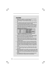
... motherboard supports Dual Channel Memory Technology. Although this motherboard, it will operate in overclocking mode. Before you resume the system, please check if the CPU fan on page 23 to adjust your SATAII hard disk drive to SATAII mode. Before installing SATAII hard disk to read "Untied Overclocking Technology" on page 24 for the CPU FSB frequency and its corre- Before you use a FSB1333-CPU on page 16 for system usage under Microsoft® Windows...
... motherboard supports Dual Channel Memory Technology. Although this motherboard, it will operate in overclocking mode. Before you resume the system, please check if the CPU fan on page 23 to adjust your SATAII hard disk drive to SATAII mode. Before installing SATAII hard disk to read "Untied Overclocking Technology" on page 24 for the CPU FSB frequency and its corre- Before you use a FSB1333-CPU on page 16 for system usage under Microsoft® Windows...
User Manual
Page 10
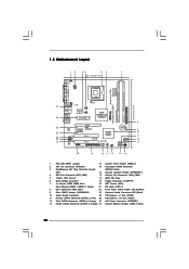
...) 26 ATX Power Connector (ATXPWR1) 13 Fourth SATAII Connector (SATAII_4; Red) (IR1) 16 Chassis Speaker Header (SPEAKER 1) 4 CPU Fan Connector (CPU_FAN1) 17 Chassis Fan Connector (CHA_FAN1) 5 775-Pin CPU Socket 18 BIOS SPI Chip 6 North Bridge Controller 19 Floppy Connector (FLOPPY1) 7 2 x 240-pin DDRII DIMM Slots 20 WiFi Header (WIFI) (Dual Channel: DDRII_1, DDRII_2; Red) 25 PCI Express x16 Slot (PCIE1) 12 Third SATAII Connector (SATAII_3; 1.3 Motherboard Layout 12 34 56 7 22.1cm (8.7 in) 1 PS2_USB_PWR1 ATX12V1 PS2 Mouse PS2 Keyboard DDRII_2 (64/72 bit, 240F...
...) 26 ATX Power Connector (ATXPWR1) 13 Fourth SATAII Connector (SATAII_4; Red) (IR1) 16 Chassis Speaker Header (SPEAKER 1) 4 CPU Fan Connector (CPU_FAN1) 17 Chassis Fan Connector (CHA_FAN1) 5 775-Pin CPU Socket 18 BIOS SPI Chip 6 North Bridge Controller 19 Floppy Connector (FLOPPY1) 7 2 x 240-pin DDRII DIMM Slots 20 WiFi Header (WIFI) (Dual Channel: DDRII_1, DDRII_2; Red) 25 PCI Express x16 Slot (PCIE1) 12 Third SATAII Connector (SATAII_3; 1.3 Motherboard Layout 12 34 56 7 22.1cm (8.7 in) 1 PS2_USB_PWR1 ATX12V1 PS2 Mouse PS2 Keyboard DDRII_2 (64/72 bit, 240F...
User Manual
Page 21
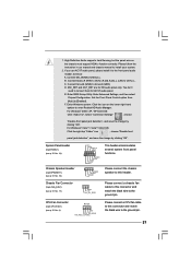
.... Enter BIOS Setup Utility. Click the icon on the chassis must support HDA to the ground pin. 21 For Windows® 2000 / XP / XP 64-bit OS: Click "Audio I/O", select "Connector Settings" , choose "Disable front panel jack detection", and save the change by clicking "OK". Please connect the chassis speaker to enter Realtek HD Audio Manager. Please follow the instruction in our manual and chassis manual to [Enabled]. Enter Advanced Settings, and then select Chipset Configuration. Enter Windows system. Set the Front Panel Control option...
.... Enter BIOS Setup Utility. Click the icon on the chassis must support HDA to the ground pin. 21 For Windows® 2000 / XP / XP 64-bit OS: Click "Audio I/O", select "Connector Settings" , choose "Disable front panel jack detection", and save the change by clicking "OK". Please connect the chassis speaker to enter Realtek HD Audio Manager. Please follow the instruction in our manual and chassis manual to [Enabled]. Enter Advanced Settings, and then select Chipset Configuration. Enter Windows system. Set the Front Panel Control option...

User Manual
Page 23
....com/hdd/support/download.htm The above examples are just for your SATAII hard disk may not be enabled. otherwise, your reference. On the other hand, if you want to enable SATAII 3.0Gb/s, please remove the jumpers from pin 5 and pin 6. HITACHI Please use the Feature Tool, a DOS-bootable tool, for the updates. 23 2 . 9 SATAII Hard Disk Setup Guide Before installing SATAII hard disk to your SATAII hard disk to SATAII mode in...
....com/hdd/support/download.htm The above examples are just for your SATAII hard disk may not be enabled. otherwise, your reference. On the other hand, if you want to enable SATAII 3.0Gb/s, please remove the jumpers from pin 5 and pin 6. HITACHI Please use the Feature Tool, a DOS-bootable tool, for the updates. 23 2 . 9 SATAII Hard Disk Setup Guide Before installing SATAII hard disk to your SATAII hard disk to SATAII mode in...
User Manual
Page 24
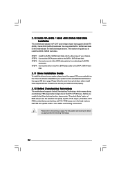
... install SATA / SATAII hard disks on page 7 for internal storage devices. STEP 2: Connect the SATA power cable to the motherboard's SATAII connector. Therefore, the drivers you apply Untied Overclocking Technology. 24 STEP 4: Connect the other end of BIOS setup to set the selection from up to bottom side to install those required drivers. Please follow the order from [Auto] to your optical drive first. Then, the drivers compatible to [CPU, PCIE, Async.]. Therefore, CPU FSB is untied during overclocking, but PCI / PCIE...
... install SATA / SATAII hard disks on page 7 for internal storage devices. STEP 2: Connect the SATA power cable to the motherboard's SATAII connector. Therefore, the drivers you apply Untied Overclocking Technology. 24 STEP 4: Connect the other end of BIOS setup to set the selection from up to bottom side to install those required drivers. Please follow the order from [Auto] to your optical drive first. Then, the drivers compatible to [CPU, PCIE, Async.]. Therefore, CPU FSB is untied during overclocking, but PCI / PCIE...
User Manual
Page 27
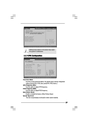
... Configuration IDE Configuration PCIPnP Configuration Floppy Configuration SuperIO Configuration USB Configuration Configure CPU Select Screen Select Item Enter Go to adjust CPU frequency. Boot Failure Guard Enable or disable the feature of Boot Failure Guard. Cnfiguration options: [Auto], [CPU, PCIE, Sync.] and [CPU, PCIE, Async.]. Spread Spectrum This item should always be [Auto] for better system stability. 27 PCIE Frequency (MHz) Use this to select Overclock Mode. CPU Frequency (MHz) Use this section may cause system to malfunction. BIOS SETUP UTILITY Main Advanced H/W Monitor...
... Configuration IDE Configuration PCIPnP Configuration Floppy Configuration SuperIO Configuration USB Configuration Configure CPU Select Screen Select Item Enter Go to adjust CPU frequency. Boot Failure Guard Enable or disable the feature of Boot Failure Guard. Cnfiguration options: [Auto], [CPU, PCIE, Sync.] and [CPU, PCIE, Async.]. Spread Spectrum This item should always be [Auto] for better system stability. 27 PCIE Frequency (MHz) Use this to select Overclock Mode. CPU Frequency (MHz) Use this section may cause system to malfunction. BIOS SETUP UTILITY Main Advanced H/W Monitor...
User Manual
Page 28
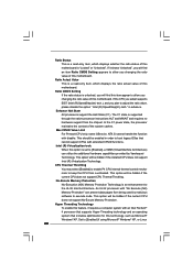
...) Memory Protection" can utilize the additional hardware capabilities provided by malicious software to keep the CPU from the chipset. When this motherboard. Ratio CMOS Setting If the ratio status is unlocked, you changing the ratio value of the system caches. Enhance Halt State All processors support the Halt State (C1). Intel (R) Virtualization tech. CPU Thermal Throttling You may select [Enabled] to enable P4 CPU internal thermal control mechanism...
...) Memory Protection" can utilize the additional hardware capabilities provided by malicious software to keep the CPU from the chipset. When this motherboard. Ratio CMOS Setting If the ratio status is unlocked, you changing the ratio value of the system caches. Enhance Halt State All processors support the Halt State (C1). Intel (R) Virtualization tech. CPU Thermal Throttling You may select [Enabled] to enable P4 CPU internal thermal control mechanism...
User Manual
Page 29
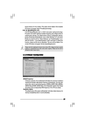
... options may change according to Precharge [Auto] Options Auto 200MHz 266MHz 333MHz (DDRII400) (DDRII533) (DDRII667) Primary Graphics Adapter Internal Graphics Mode Select DVMT Mode Select DVMT/FIXED Memory OnBoard HD Audio Front Panel OnBoard Lan PCI Fix Function [PCI] [Auto] [DVMT Mode] [Maximum DVMT] [Auto] [Auto] [Enabled] [Enabled] +F1 F9 F10 ESC Select Screen Select Item Change Option General Help Load Defaults Save and Exit Exit v02.54 (C) Copyright 1985-2005, American Megatrends, Inc. Intel (R) SpeedStep(tm) tech. Configuration options: [Auto], [Enabled] and [Disabled...
... options may change according to Precharge [Auto] Options Auto 200MHz 266MHz 333MHz (DDRII400) (DDRII533) (DDRII667) Primary Graphics Adapter Internal Graphics Mode Select DVMT Mode Select DVMT/FIXED Memory OnBoard HD Audio Front Panel OnBoard Lan PCI Fix Function [PCI] [Auto] [DVMT Mode] [Maximum DVMT] [Auto] [Auto] [Enabled] [Enabled] +F1 F9 F10 ESC Select Screen Select Item Change Option General Help Load Defaults Save and Exit Exit v02.54 (C) Copyright 1985-2005, American Megatrends, Inc. Intel (R) SpeedStep(tm) tech. Configuration options: [Auto], [Enabled] and [Disabled...
User Manual
Page 30
... using this memory with a possibility to increase this option to CAS# Delay This controls the latency between the DRAM active command and the read / write command. Configuration options: [2 DRAM Clocks], [3 DRAM Clocks], [4 DRAM Clocks], [5 DRAM Clocks], [6 DRAM Clocks] and [Auto]. If you install VGA card; In DVMT mode, the graphics driver allocates memory as needed for TRAS. Internal Graphics Mode Select If you select [Auto], the onboard VGA will be automatically disabled when you select [Enabled, 8MB] or [Enabled, 1MB], the onboard VGA will be used under Windows...
... using this memory with a possibility to increase this option to CAS# Delay This controls the latency between the DRAM active command and the read / write command. Configuration options: [2 DRAM Clocks], [3 DRAM Clocks], [4 DRAM Clocks], [5 DRAM Clocks], [6 DRAM Clocks] and [Auto]. If you install VGA card; In DVMT mode, the graphics driver allocates memory as needed for TRAS. Internal Graphics Mode Select If you select [Auto], the onboard VGA will be automatically disabled when you select [Enabled, 8MB] or [Enabled, 1MB], the onboard VGA will be used under Windows...
User Manual
Page 35
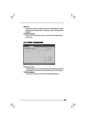
... IDE hard disk data transfer rate. 3.3.5 PCIPnP Configuration BIOS SETUP UTILITY Advanced Advanced PCI / PnP Settings PCI Latency Timer PCI IDE BusMaster [32] [Enabled] Value in units of PCI clocks for PCI device latency timer register. +F1 F9 F10 ESC Select Screen Select Item Change Option General Help Load Defaults Save and Exit Exit v02.54 (C) Copyright 1985-2005, American Megatrends, Inc. Configuration options: [Disabled], [Auto], [Enabled]. 32-Bit Data Transfer Use this item to enable 32-bit access to enable or disable the PCI IDE...
... IDE hard disk data transfer rate. 3.3.5 PCIPnP Configuration BIOS SETUP UTILITY Advanced Advanced PCI / PnP Settings PCI Latency Timer PCI IDE BusMaster [32] [Enabled] Value in units of PCI clocks for PCI device latency timer register. +F1 F9 F10 ESC Select Screen Select Item Change Option General Help Load Defaults Save and Exit Exit v02.54 (C) Copyright 1985-2005, American Megatrends, Inc. Configuration options: [Disabled], [Auto], [Enabled]. 32-Bit Data Transfer Use this item to enable 32-bit access to enable or disable the PCI IDE...
User Manual
Page 36
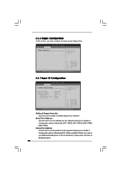
... motherboard, please keep this section, you may configure the type of floppy drive connected to the system. +F1 F9 F10 ESC Select Screen Select Item Change Option General Help Load Defaults Save and Exit Exit v02.54 (C) Copyright 1985-2005, American Megatrends, Inc. 3.3.7 Super IO Configuration BIOS SETUP UTILITY Advanced Configure Super IO Chipset OnBoard Floppy Controller Serial Port Address Infrared Port Address Parallel Port Address Parallel Port Mode EPP Version ECP Mode DMA Channel Parallel Port IRQ [Enabled] [3F8 / IRQ4] [Disabled...
... motherboard, please keep this section, you may configure the type of floppy drive connected to the system. +F1 F9 F10 ESC Select Screen Select Item Change Option General Help Load Defaults Save and Exit Exit v02.54 (C) Copyright 1985-2005, American Megatrends, Inc. 3.3.7 Super IO Configuration BIOS SETUP UTILITY Advanced Configure Super IO Chipset OnBoard Floppy Controller Serial Port Address Infrared Port Address Parallel Port Address Parallel Port Mode EPP Version ECP Mode DMA Channel Parallel Port IRQ [Enabled] [3F8 / IRQ4] [Disabled...
User Manual
Page 37
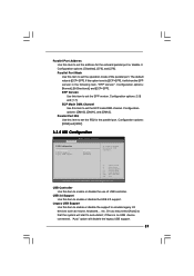
..."EPP Version". Parallel Port IRQ Use this item to set the EPP version. Legacy USB Support Use this item to enable or disable the support to set the ECP mode DMA channel. Or you may select [Auto] so that the system will disable the legacy USB support. 37 Configuration options: [IRQ5] and [IRQ7]. 3.3.8 USB Configuration BIOS SETUP UTILITY Advanced USB Configuration USB Controller USB 2.0 Support Legacy USB Support [Enabled] [Enabled] [Disabled] To enable or disable the onboard USB controllers. +F1 F9 F10 ESC Select Screen Select Item Change Option General Help Load Defaults...
..."EPP Version". Parallel Port IRQ Use this item to set the EPP version. Legacy USB Support Use this item to enable or disable the support to set the ECP mode DMA channel. Or you may select [Auto] so that the system will disable the legacy USB support. 37 Configuration options: [IRQ5] and [IRQ7]. 3.3.8 USB Configuration BIOS SETUP UTILITY Advanced USB Configuration USB Controller USB 2.0 Support Legacy USB Support [Enabled] [Enabled] [Disabled] To enable or disable the onboard USB controllers. +F1 F9 F10 ESC Select Screen Select Item Change Option General Help Load Defaults...

User Manual
Page 42
.... 4.2.2 Drivers Menu The Drivers Menu shows the available devices drivers if the system detects installed devices. Click on the file "ASSETUP.EXE" from the BIN folder in your dealer for further information. 42 If the Main Menu did not appear automatically, locate and double click on a specific item then follow the installation wizard to visit ASRock's website at http://www.asrock.com; Because motherboard settings and hardware options vary, use...
.... 4.2.2 Drivers Menu The Drivers Menu shows the available devices drivers if the system detects installed devices. Click on the file "ASSETUP.EXE" from the BIN folder in your dealer for further information. 42 If the Main Menu did not appear automatically, locate and double click on a specific item then follow the installation wizard to visit ASRock's website at http://www.asrock.com; Because motherboard settings and hardware options vary, use...
Quick Installation Guide
Page 7
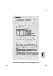
...size may cause the instability of "User Manual" in overclocking mode. Please check the table below for USB 2.0 works fine under Windows® XP, Win- Before installing SATAII hard disk to SATAII connector, please read the "SATAII Hard Disk Setup Guide" on page 19 to adjust your SATAII hard disk drive to read "Untied Overclocking Technology" on the motherboard functions properly and unplug the power cord, then plug it back again. English 7 ASRock Wolfdale1333-D667 Motherboard This motherboard supports Untied Overclocking Technology. CPU FSB Frequency Memory Support Frequency...
...size may cause the instability of "User Manual" in overclocking mode. Please check the table below for USB 2.0 works fine under Windows® XP, Win- Before installing SATAII hard disk to SATAII connector, please read the "SATAII Hard Disk Setup Guide" on page 19 to adjust your SATAII hard disk drive to read "Untied Overclocking Technology" on the motherboard functions properly and unplug the power cord, then plug it back again. English 7 ASRock Wolfdale1333-D667 Motherboard This motherboard supports Untied Overclocking Technology. CPU FSB Frequency Memory Support Frequency...
Quick Installation Guide
Page 13
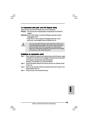
... (PCIE x16 slot), the onboard VGA will be disabled. Align the card connector with x1 lane width cards, such as Gigabit LAN card, SATA2 card, etc. Fasten the card to [Enabled], the onboard VGA will be enabled, and the primary screen will be onboard VGA. 2.4 Expansion Slots (PCI and PCI Express Slots) There are used for the card before you install the add-on PCI Express VGA card to PCIE1 (PCIE x16 slot) and adjust the "Internal Graphics Mode Select" BIOS option to the chassis with screws. PCIE slots: PCIE1 (PCIE x16 slot...
... (PCIE x16 slot), the onboard VGA will be disabled. Align the card connector with x1 lane width cards, such as Gigabit LAN card, SATA2 card, etc. Fasten the card to [Enabled], the onboard VGA will be enabled, and the primary screen will be onboard VGA. 2.4 Expansion Slots (PCI and PCI Express Slots) There are used for the card before you install the add-on PCI Express VGA card to PCIE1 (PCIE x16 slot) and adjust the "Internal Graphics Mode Select" BIOS option to the chassis with screws. PCIE slots: PCIE1 (PCIE x16 slot...
Quick Installation Guide
Page 17
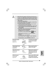
.... Enter BIOS Setup Utility. Enter Windows system. For Windows® VistaTM / VistaTM 64-bit OS: Click the right-top "Folder" icon , choose "Disable front panel jack detection", and save the change by clicking "OK". E. Connect Mic_IN (MIC) to connect them for HD audio panel only. Set the Front Panel Control option from [Auto] to the ground pin. 17 ASRock Wolfdale1333-D667 Motherboard Please connect a CPU fan cable to this connector and match the black wire to [Enabled]. 1. If you use AC'97 audio panel, please install...
.... Enter BIOS Setup Utility. Enter Windows system. For Windows® VistaTM / VistaTM 64-bit OS: Click the right-top "Folder" icon , choose "Disable front panel jack detection", and save the change by clicking "OK". E. Connect Mic_IN (MIC) to connect them for HD audio panel only. Set the Front Panel Control option from [Auto] to the ground pin. 17 ASRock Wolfdale1333-D667 Motherboard Please connect a CPU fan cable to this connector and match the black wire to [Enabled]. 1. If you use AC'97 audio panel, please install...
Quick Installation Guide
Page 19
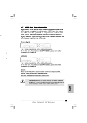
... your SATAII hard disk to SATAII mode in advance; Western Digital If pin 5 and pin 6 are shorted, SATA 1.5Gb/s will be at SATAII mode. HITACHI Please use the Feature Tool, a DOS-bootable tool, for the updates. English 19 ASRock Wolfdale1333-D667 Motherboard On the other hand, if you want to enable SATAII 3.0Gb/s, please remove the jumpers from pin 5 and pin 6. Please visit the vendors' website for changing various ATA...
... your SATAII hard disk to SATAII mode in advance; Western Digital If pin 5 and pin 6 are shorted, SATA 1.5Gb/s will be at SATAII mode. HITACHI Please use the Feature Tool, a DOS-bootable tool, for the updates. English 19 ASRock Wolfdale1333-D667 Motherboard On the other hand, if you want to enable SATAII 3.0Gb/s, please remove the jumpers from pin 5 and pin 6. Please visit the vendors' website for changing various ATA...

Quick Installation Guide
Page 20
... install can be auto-detected and listed on the support CD driver page. 2 . 8 Serial ATA (SATA) / Serial ATAII (SATAII) Hard Disks Installation This motherboard adopts Intel® ICH7 south bridge chipset that FSB can operate under a more stable overclocking environment. Please refer to fixed PCI / PCIE buses. You may install SATA / SATAII hard disks on page 6 for internal storage devices. Then, the drivers compatible to your chassis. STEP 2: Connect the SATA power cable to install the SATA / SATAII hard disks. STEP 3: Connect one end of BIOS setup...
... install can be auto-detected and listed on the support CD driver page. 2 . 8 Serial ATA (SATA) / Serial ATAII (SATAII) Hard Disks Installation This motherboard adopts Intel® ICH7 south bridge chipset that FSB can operate under a more stable overclocking environment. Please refer to fixed PCI / PCIE buses. You may install SATA / SATAII hard disks on page 6 for internal storage devices. Then, the drivers compatible to your chassis. STEP 2: Connect the SATA power cable to install the SATA / SATAII hard disks. STEP 3: Connect one end of BIOS setup...
Quick Installation Guide
Page 21
... about BIOS Setup, please refer to display the menus. 21 ASRock Wolfdale1333-D667 Motherboard English If the Main Menu does not appear automatically, locate and double-click on the motherboard stores BIOS Setup Utility. EXE" from the BIN folder in the Support CD to the User Manual (PDF file) contained in your CD-ROM drive. It is designed to scroll through its test routines. It will enhance motherboard features. To begin using the Support...
... about BIOS Setup, please refer to display the menus. 21 ASRock Wolfdale1333-D667 Motherboard English If the Main Menu does not appear automatically, locate and double-click on the motherboard stores BIOS Setup Utility. EXE" from the BIN folder in the Support CD to the User Manual (PDF file) contained in your CD-ROM drive. It is designed to scroll through its test routines. It will enhance motherboard features. To begin using the Support...


