Intel Rapid Storage Guide
Page 13
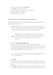
... successfully installed the driver and Windows setup should continue. Press Enter to scroll through the list as all controllers may not be prompted Note with the Note necessary files. 4. Press S to install the Intel Rapid Storage Technology driver during text-mode phase). At this point, you see a message in the status line that says, Please insert the disk labeled Manufacturer-supplied hardware support disk into Drive A:, insert ;a floppy disk containing...
... successfully installed the driver and Windows setup should continue. Press Enter to scroll through the list as all controllers may not be prompted Note with the Note necessary files. 4. Press S to install the Intel Rapid Storage Technology driver during text-mode phase). At this point, you see a message in the status line that says, Please insert the disk labeled Manufacturer-supplied hardware support disk into Drive A:, insert ;a floppy disk containing...

Intel Smart Response Installation Guide
Page 1
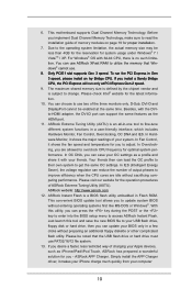
... storage driver version 10.5 or later. 2. You MUST have both the HDD you want to use Enhanced or Maximized Mode. 6. It is not necessary to build RAID 0 or RAID 1 in Icon tray, lower right-hand corner of the screen. 4. You can find the UI setup instruction and the step by double-clicking RST Storage icon in RAID ROM. UI setup instruction: 1. Intel Smart Response Technology Installation Guide This motherboard supports Intel Smart Response Technology...
... storage driver version 10.5 or later. 2. You MUST have both the HDD you want to use Enhanced or Maximized Mode. 6. It is not necessary to build RAID 0 or RAID 1 in Icon tray, lower right-hand corner of the screen. 4. You can find the UI setup instruction and the step by double-clicking RST Storage icon in RAID ROM. UI setup instruction: 1. Intel Smart Response Technology Installation Guide This motherboard supports Intel Smart Response Technology...

User Manual
Page 8
... - ASRock Internet Flash (see CAUTION 21) - ASRock U-COP (see CAUTION 20) - Boot Failure Guard (B.F.G.) - Good Night LED - ACPI 1.1 Compliance Wake Up Events - ASRock Extreme Tuning Utility (AXTU) (see CAUTION 17) - ASRock XFast RAM (see CAUTION 11) - Front panel audio connector - 2 x USB 2.0 headers (support 4 USB 2.0 ports) - 1 x USB 3.0 header (supports 2 USB 3.0 ports) - 64Mb AMI UEFI Legal BIOS with GUI support - ASRock OMG (Online Management Guard) (see CAUTION 22) - CPU/Chassis/Power FAN connector - 24 pin ATX power connector - 8 pin 12V power connector - Supports...
... - ASRock Internet Flash (see CAUTION 21) - ASRock U-COP (see CAUTION 20) - Boot Failure Guard (B.F.G.) - Good Night LED - ACPI 1.1 Compliance Wake Up Events - ASRock Extreme Tuning Utility (AXTU) (see CAUTION 17) - ASRock XFast RAM (see CAUTION 11) - Front panel audio connector - 2 x USB 2.0 headers (support 4 USB 2.0 ports) - 1 x USB 3.0 header (supports 2 USB 3.0 ports) - 64Mb AMI UEFI Legal BIOS with GUI support - ASRock OMG (Online Management Guard) (see CAUTION 22) - CPU/Chassis/Power FAN connector - 24 pin ATX power connector - 8 pin 12V power connector - Supports...
User Manual
Page 10
... much quickly from your USB flash drive, floppy disk or hard drive, then you to access ASRock Instant Flash. Besides, with 64-bit CPU, there is subject to utilize the memory that the USB flash drive or hard drive must use . 8. Please be less than 4GB for the reservation for the latest information. 10. 6. ASRock Instant Flash is an all-in Flash ROM. This motherboard supports Dual Channel Memory Technology. The maximum shared memory size is defined by the chipset vendor and is...
... much quickly from your USB flash drive, floppy disk or hard drive, then you to access ASRock Instant Flash. Besides, with 64-bit CPU, there is subject to utilize the memory that the USB flash drive or hard drive must use . 8. Please be less than 4GB for the reservation for the latest information. 10. 6. ASRock Instant Flash is an all-in Flash ROM. This motherboard supports Dual Channel Memory Technology. The maximum shared memory size is defined by the chipset vendor and is...

User Manual
Page 13
...) 25 USB 2.0 Header (USB6_7, Black) 7 2 x 240-pin DDR3 DIMM Slots 26 Consumer Infrared Module Header (DDR3_A2, DDR3_B2, Black) (CIR1, Gray) 8 ATX Power Connector (ATXPWR1) 27 TPM Header (TPM1) 9 USB 3.0 Header (USB3_2_3, Black) 28 Infrared Module Header (IR1) 10 Intel Q77 Chipset 29 Print Port Header (LPT1) 11 Chassis Fan Connector (CHA_FAN2) 30 COM Port Header (COM1) 12 SPI Flash Memory (64Mb) 31 Front Panel Audio Header 13 Chassis Fan Connector (CHA_FAN1) (HD_AUDIO1, Black) 14 Chassis Speaker Header (SPEAKER1, Black) 32 PCI Express 2.0 x16 Slot...
...) 25 USB 2.0 Header (USB6_7, Black) 7 2 x 240-pin DDR3 DIMM Slots 26 Consumer Infrared Module Header (DDR3_A2, DDR3_B2, Black) (CIR1, Gray) 8 ATX Power Connector (ATXPWR1) 27 TPM Header (TPM1) 9 USB 3.0 Header (USB3_2_3, Black) 28 Infrared Module Header (IR1) 10 Intel Q77 Chipset 29 Print Port Header (LPT1) 11 Chassis Fan Connector (CHA_FAN2) 30 COM Port Header (COM1) 12 SPI Flash Memory (64Mb) 31 Front Panel Audio Header 13 Chassis Fan Connector (CHA_FAN1) (HD_AUDIO1, Black) 14 Chassis Speaker Header (SPEAKER1, Black) 32 PCI Express 2.0 x16 Slot...

User Manual
Page 24
...'s website for details. Click "View", select "CrossFireXTM", and then check the item "Enable CrossFireXTM". Select "2 GPUs" and click "Apply" (if you have Microsoft .NET Framework installed prior to uninstall any VGA drivers installed in your computer and boot into OS. AMD Catalyst Control Center Step 6. Step 4. Remove the AMD drivers if you install two Radeon graphics cards). 24 2.7.2 Driver Installation and Setup Step 1. Double-click "AMD Catalyst Control Center".
...'s website for details. Click "View", select "CrossFireXTM", and then check the item "Enable CrossFireXTM". Select "2 GPUs" and click "Apply" (if you have Microsoft .NET Framework installed prior to uninstall any VGA drivers installed in your computer and boot into OS. AMD Catalyst Control Center Step 6. Step 4. Remove the AMD drivers if you install two Radeon graphics cards). 24 2.7.2 Driver Installation and Setup Step 1. Double-click "AMD Catalyst Control Center".

User Manual
Page 29
... ASRock motherboard. USB 2.0 header (9-pin, black) CIR header (4-pin, gray) Step2. Connect the front USB cable to the USB 2.0 header on your system. Step5. Press or to the front USB port. Please make sure the wire assignments and the PP+ GND DUMMY pin assignments are matched correctly. Step1. Make sure the option "CIR Controller" is listed at the bottom of ASRock Smart Remote. Install the Multi-Angle CIR Receiver to enter the BIOS Setup Utility. 2.9 ASRock Smart Remote Installation Guide ASRock Smart...
... ASRock motherboard. USB 2.0 header (9-pin, black) CIR header (4-pin, gray) Step2. Connect the front USB cable to the USB 2.0 header on your system. Step5. Press or to the front USB port. Please make sure the wire assignments and the PP+ GND DUMMY pin assignments are matched correctly. Step1. Make sure the option "CIR Controller" is listed at the bottom of ASRock Smart Remote. Install the Multi-Angle CIR Receiver to enter the BIOS Setup Utility. 2.9 ASRock Smart Remote Installation Guide ASRock Smart...

User Manual
Page 42
... to install those required drivers. Please refer to the document in the Support CD, "Guide to SATA Hard Disks Installation and RAID Configuration", which is not supported under Windows® XP / XP 64-bit. Set the option "SATA Mode Selection" to [RAID] for RAID configuration. Before you start to configure the RAID function, you want to use both "RAID Installation Guide" and "Intel Rapid Storage Information" for SATA2_2 to SATA2_5 and SATA3_0 and SATA3_1 ports. 2.17 Driver Installation Guide To install the drivers to...
... to install those required drivers. Please refer to the document in the Support CD, "Guide to SATA Hard Disks Installation and RAID Configuration", which is not supported under Windows® XP / XP 64-bit. Set the option "SATA Mode Selection" to [RAID] for RAID configuration. Before you start to configure the RAID function, you want to use both "RAID Installation Guide" and "Intel Rapid Storage Information" for SATA2_2 to SATA2_5 and SATA3_0 and SATA3_1 ports. 2.17 Driver Installation Guide To install the drivers to...

User Manual
Page 52
... Processor Cores Use this to enable or disable CPU C3 (ACPI C2) report to keep the CPU from the chipset. The C1 state is supported through the native processor instructions HLT and MWAIT and requires no hardware support from overheating. Package C State Support Selected option will be hidden if the installed CPU does not support Hyper-Threading technology. No-Execute Memory Protection No-Execution (NX) Memory Protection Technology is [All]. CPU C3 State Support Use...
... Processor Cores Use this to enable or disable CPU C3 (ACPI C2) report to keep the CPU from the chipset. The C1 state is supported through the native processor instructions HLT and MWAIT and requires no hardware support from overheating. Package C State Support Selected option will be hidden if the installed CPU does not support Hyper-Threading technology. No-Execute Memory Protection No-Execution (NX) Memory Protection Technology is [All]. CPU C3 State Support Use...

User Manual
Page 54
... install a PCI Express card under Windows® XP / VistaTM OS, please disable this to enable or disable Render Standby by Internal Graphics Device. The default value is [Disabled]. VT-d Use this item to enable or disable IGPU Multi-Monitor. The default value is [Enabled]. IGPU Multi-Monitor This allows you to enable/disable Intel(R) Virtualization Technology for Directed I/O. The default value is [Auto]. 3.4.2 North Bridge Configuration Primary Graphics Adapter This allows you to set onboard VGA share memory feature. The default value is [Enabled...
... install a PCI Express card under Windows® XP / VistaTM OS, please disable this to enable or disable Render Standby by Internal Graphics Device. The default value is [Disabled]. VT-d Use this item to enable or disable IGPU Multi-Monitor. The default value is [Enabled]. IGPU Multi-Monitor This allows you to enable/disable Intel(R) Virtualization Technology for Directed I/O. The default value is [Auto]. 3.4.2 North Bridge Configuration Primary Graphics Adapter This allows you to set onboard VGA share memory feature. The default value is [Enabled...

User Manual
Page 63
... for legacy USB. [Auto] - USB 3.0 Controller Use this item to enable or disable legacy support for USB 3.0 devices. Please refer to enter OS. [UEFI Setup Only] - Enables legacy support if USB devices are four configuration options: [Enabled], [Auto], [Disabled] and [UEFI Setup Only]. If you have USB compatibility issues, it is selected. Legacy USB Support Use this option to enable or disable the use of USB 2.0 controller. There are connected. [Disabled] - 3.4.10 USB Configuration USB 2.0 Controller Use this item to select legacy support for USB devices. The default...
... for legacy USB. [Auto] - USB 3.0 Controller Use this item to enable or disable legacy support for USB 3.0 devices. Please refer to enter OS. [UEFI Setup Only] - Enables legacy support if USB devices are four configuration options: [Enabled], [Auto], [Disabled] and [UEFI Setup Only]. If you have USB compatibility issues, it is selected. Legacy USB Support Use this option to enable or disable the use of USB 2.0 controller. There are connected. [Disabled] - 3.4.10 USB Configuration USB 2.0 Controller Use this item to select legacy support for USB devices. The default...

User Manual
Page 65
...Over Temperature Protection Use this section, it allows you to monitor the status of the hardware on your system, including the parameters of the CPU temperature, motherboard temperature, CPU fan speed, chassis fan speed, and the critical voltage. Configuration options: [Full On] and [Automatic Mode]. Configuration options: [Full On], [Automatic Mode] and [Manual]. Chassis Fan 2 Setting This allows you to set chassis fan 2's speed. The default value is [Full On]. 3.5 Hardware Health Event Monitoring Screen In this to enable or disable Over Temperature Protection. CPU Fan 1 & 2 Setting...
...Over Temperature Protection Use this section, it allows you to monitor the status of the hardware on your system, including the parameters of the CPU temperature, motherboard temperature, CPU fan speed, chassis fan speed, and the critical voltage. Configuration options: [Full On] and [Automatic Mode]. Configuration options: [Full On], [Automatic Mode] and [Manual]. Chassis Fan 2 Setting This allows you to set chassis fan 2's speed. The default value is [Full On]. 3.5 Hardware Health Event Monitoring Screen In this to enable or disable Over Temperature Protection. CPU Fan 1 & 2 Setting...

User Manual
Page 69
... This motherboard supports various Microsoft® Windows® operating systems: 7 / 7 64-bit / VistaTM / VistaTM 64-bit / XP / XP 64-bit. Because motherboard settings and hardware options vary, use the setup procedures in your dealer for more about ASRock, welcome to install it. 4.2.4 Contact Information If you may contact your computer. or you need to contact ASRock or want to display the menu. 4.2.2 Drivers Menu The Drivers Menu shows the available device's drivers...
... This motherboard supports various Microsoft® Windows® operating systems: 7 / 7 64-bit / VistaTM / VistaTM 64-bit / XP / XP 64-bit. Because motherboard settings and hardware options vary, use the setup procedures in your dealer for more about ASRock, welcome to install it. 4.2.4 Contact Information If you may contact your computer. or you need to contact ASRock or want to display the menu. 4.2.2 Drivers Menu The Drivers Menu shows the available device's drivers...

Quick Installation Guide
Page 2
...) 25 USB 2.0 Header (USB6_7, Black) 7 2 x 240-pin DDR3 DIMM Slots 26 Consumer Infrared Module Header (DDR3_A2, DDR3_B2, Black) (CIR1, Gray) 8 ATX Power Connector (ATXPWR1) 27 TPM Header (TPM1) 9 USB 3.0 Header (USB3_2_3, Black) 28 Infrared Module Header (IR1) 10 Intel Q77 Chipset 29 Print Port Header (LPT1) 11 Chassis Fan Connector (CHA_FAN2) 30 COM Port Header (COM1) 12 SPI Flash Memory (64Mb) 31 Front Panel Audio Header 13 Chassis Fan Connector (CHA_FAN1) (HD_AUDIO1, Black) 14 Chassis Speaker Header (SPEAKER1, Black) 32 PCI Express 2.0 x16 Slot...
...) 25 USB 2.0 Header (USB6_7, Black) 7 2 x 240-pin DDR3 DIMM Slots 26 Consumer Infrared Module Header (DDR3_A2, DDR3_B2, Black) (CIR1, Gray) 8 ATX Power Connector (ATXPWR1) 27 TPM Header (TPM1) 9 USB 3.0 Header (USB3_2_3, Black) 28 Infrared Module Header (IR1) 10 Intel Q77 Chipset 29 Print Port Header (LPT1) 11 Chassis Fan Connector (CHA_FAN2) 30 COM Port Header (COM1) 12 SPI Flash Memory (64Mb) 31 Front Panel Audio Header 13 Chassis Fan Connector (CHA_FAN1) (HD_AUDIO1, Black) 14 Chassis Speaker Header (SPEAKER1, Black) 32 PCI Express 2.0 x16 Slot...

Quick Installation Guide
Page 7
Front panel audio connector - 2 x USB 2.0 headers (support 4 USB 2.0 ports) - 1 x USB 3.0 header (supports 2 USB 3.0 ports) - 64Mb AMI UEFI Legal BIOS with GUI support - ASRock Instant Boot - ASRock SmartView (see CAUTION 22) - Combo Cooler Option (C.C.O.) (see CAUTION 14) - ASRock XFast LAN (see CAUTION 15) - CPU/Chassis/Power FAN connector - 24 pin ATX power connector - 8 pin 12V power connector - Good Night LED - ASRock XFast USB (see CAUTION 16) - ASRock XFast RAM (see CAUTION 20) - ASRock Internet Flash (see CAUTION 17) - Hybrid Booster: - Boot Failure Guard ...
Front panel audio connector - 2 x USB 2.0 headers (support 4 USB 2.0 ports) - 1 x USB 3.0 header (supports 2 USB 3.0 ports) - 64Mb AMI UEFI Legal BIOS with GUI support - ASRock Instant Boot - ASRock SmartView (see CAUTION 22) - Combo Cooler Option (C.C.O.) (see CAUTION 14) - ASRock XFast LAN (see CAUTION 15) - CPU/Chassis/Power FAN connector - 24 pin ATX power connector - 8 pin 12V power connector - Good Night LED - ASRock XFast USB (see CAUTION 16) - ASRock XFast RAM (see CAUTION 20) - ASRock Internet Flash (see CAUTION 17) - Hybrid Booster: - Boot Failure Guard ...

Quick Installation Guide
Page 9
... 16 for you install a Sandy Bridge CPU, the PCI Express will run the PCI Express in a few clicks without entering operating systems first like MS-DOS or Windows®. ASRock Instant Flash is an all-in-one tool to fine-tune different system functions in Flash ROM. This motherboard supports Dual Channel Memory Technology. ASRock Extreme Tuning Utility (AXTU) is a BIOS flash utility embedded in a user-friendly interface, which includes Hardware Monitor, Fan Control, Overclocking, OC DNA and...
... 16 for you install a Sandy Bridge CPU, the PCI Express will run the PCI Express in a few clicks without entering operating systems first like MS-DOS or Windows®. ASRock Instant Flash is an all-in-one tool to fine-tune different system functions in Flash ROM. This motherboard supports Dual Channel Memory Technology. ASRock Extreme Tuning Utility (AXTU) is a BIOS flash utility embedded in a user-friendly interface, which includes Hardware Monitor, Fan Control, Overclocking, OC DNA and...

Quick Installation Guide
Page 21
... "AMD Catalyst Control Center" on your system. English 21 ASRock Q77M vPro Motherboard Step 2. Step 4. You must have any previously installed Catalyst drivers prior to uninstall any VGA drivers installed in your system, there is an optional download. Restart your Windows® taskbar. Install the required drivers to downloading and installing the CATALYST Control Center. Please check AMD's website for AMD driver updates. AMD Catalyst Control Center Step 6. Double-click "AMD Catalyst Control Center". AMD recommends Windows® XP Service...
... "AMD Catalyst Control Center" on your system. English 21 ASRock Q77M vPro Motherboard Step 2. Step 4. You must have any previously installed Catalyst drivers prior to uninstall any VGA drivers installed in your system, there is an optional download. Restart your Windows® taskbar. Install the required drivers to downloading and installing the CATALYST Control Center. Please check AMD's website for AMD driver updates. AMD Catalyst Control Center Step 6. Double-click "AMD Catalyst Control Center". AMD recommends Windows® XP Service...

Quick Installation Guide
Page 224
... following the Windows® instructions. 5. If you encounter this problem, you install Windows® 7 64-bit / VistaTM 64-bit in the Start Menu. Disable System Restore. a. Continue to fix this problem. Then press "Enter". F. Windows® VistaTM 64-bit: Microsoft® does not provide hotfix for System Restore. Type "systempropertiesprotection" in a large hard disk (ex. b. Then Click "Turn System Restore Off" to confirm. Then Press "Ok". 224 ASRock Q77M vPro Motherboard English...
... following the Windows® instructions. 5. If you encounter this problem, you install Windows® 7 64-bit / VistaTM 64-bit in the Start Menu. Disable System Restore. a. Continue to fix this problem. Then press "Enter". F. Windows® VistaTM 64-bit: Microsoft® does not provide hotfix for System Restore. Type "systempropertiesprotection" in a large hard disk (ex. b. Then Click "Turn System Restore Off" to confirm. Then Press "Ok". 224 ASRock Q77M vPro Motherboard English...

RAID Installation Guide
Page 6
...-bit / VistaTM / VistaTM 64-bit OS, if you want to use "Intel Rapid Storage" in Windows® environment, install "SATA2 driver" from the Support CD again so that "Intel Rapid Storage" will be installed to use both "RAID Installation Guide" and "Intel Rapid Storage Information" for RAID configuration. Please refer to the document in the Support CD, "Guide to SATA Hard Disks Installation and RAID Configuration", which is located in the Support CD for SATA2_2 to set RAID configuration. B. Enter UEFI SETUP UTILITY Advanced screen Storage Configuration. Set "SATA Mode...
...-bit / VistaTM / VistaTM 64-bit OS, if you want to use "Intel Rapid Storage" in Windows® environment, install "SATA2 driver" from the Support CD again so that "Intel Rapid Storage" will be installed to use both "RAID Installation Guide" and "Intel Rapid Storage Information" for RAID configuration. Please refer to the document in the Support CD, "Guide to SATA Hard Disks Installation and RAID Configuration", which is located in the Support CD for SATA2_2 to set RAID configuration. B. Enter UEFI SETUP UTILITY Advanced screen Storage Configuration. Set "SATA Mode...

Quick Start Guide
Page 9
...; Pro Processor Technology Quick Start Guide It is recommended that the SCS software is available in order to "Intel_AMT_SCS_Installation_Guide.pdf" Part 9-10. This agent will communicate with minimum settings. For a quick start, a basic profile is located in LocalAgent subdirectory in the Profile Components section, the wizard displays the Access Control List (ACL) settings. The agent software "oobmclocalagent.msi" is created with the Intel AMT watchdog timer on installing...
...; Pro Processor Technology Quick Start Guide It is recommended that the SCS software is available in order to "Intel_AMT_SCS_Installation_Guide.pdf" Part 9-10. This agent will communicate with minimum settings. For a quick start, a basic profile is located in LocalAgent subdirectory in the Profile Components section, the wizard displays the Access Control List (ACL) settings. The agent software "oobmclocalagent.msi" is created with the Intel AMT watchdog timer on installing...


