
User Manual
Page 3
... 1 1.1 Package Contents 1 1.2 Specifications 2 1.3 Motherboard Layout 5 1.4 I/O Panel 7 Chapter 2 Installation 8 2.1 Installing Memory Modules (DIMM) 9 2.2 Expansion Slots (PCI Express Slots) 11 2.3 Jumpers Setup 12 2.4 Onboard Headers and Connectors 13 Chapter 3 Software and Utilities Operation 17 3.1 Installing Drivers 17 3.2 A-Tuning 18 3.3 Intel® Smart Connect Technology 20 3.4 ASRock Cloud 25 3.5 ASRock APP Shop 35 3.5.1 UI Overview 35 3.5.2 Apps 36 3.5.3 BIOS & Drivers 39 3.5.4 Setting 40 3.6 Start8 41 Chapter 4 UEFI SETUP UTILITY 44
... 1 1.1 Package Contents 1 1.2 Specifications 2 1.3 Motherboard Layout 5 1.4 I/O Panel 7 Chapter 2 Installation 8 2.1 Installing Memory Modules (DIMM) 9 2.2 Expansion Slots (PCI Express Slots) 11 2.3 Jumpers Setup 12 2.4 Onboard Headers and Connectors 13 Chapter 3 Software and Utilities Operation 17 3.1 Installing Drivers 17 3.2 A-Tuning 18 3.3 Intel® Smart Connect Technology 20 3.4 ASRock Cloud 25 3.5 ASRock APP Shop 35 3.5.1 UI Overview 35 3.5.2 Apps 36 3.5.3 BIOS & Drivers 39 3.5.4 Setting 40 3.6 Start8 41 Chapter 4 UEFI SETUP UTILITY 44

User Manual
Page 4
4.1 Introduction 44 4.1.1 UEFI Menu Bar 44 4.1.2 Navigation Keys 45 4.2 Main Screen 46 4.3 Advanced Screen 47 4.3.1 CPU Configuration 48 4.3.2 Chipset Configuration 50 4.3.3 Storage Configuration 52 4.3.4 Intel® Smart Connect Technology 53 4.3.5 Super IO Configuration 54 4.3.6 ACPI Configuration 55 4.3.7 USB Configuration 57 4.3.8 Trusted Computing 58 4.4 Tools 59 4.5 Hardware Health Event Monitoring Screen 61 4.6 Security Screen 62 4.7 Boot Screen 63 4.8 Exit Screen 65
4.1 Introduction 44 4.1.1 UEFI Menu Bar 44 4.1.2 Navigation Keys 45 4.2 Main Screen 46 4.3 Advanced Screen 47 4.3.1 CPU Configuration 48 4.3.2 Chipset Configuration 50 4.3.3 Storage Configuration 52 4.3.4 Intel® Smart Connect Technology 53 4.3.5 Super IO Configuration 54 4.3.6 ACPI Configuration 55 4.3.7 USB Configuration 57 4.3.8 Trusted Computing 58 4.4 Tools 59 4.5 Hardware Health Event Monitoring Screen 61 4.6 Security Screen 62 4.7 Boot Screen 63 4.8 Exit Screen 65
User Manual
Page 5
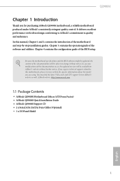
... VGA cards and CPU support list on ASRock's website without notice. Chapter 3 contains the operation guide of the BIOS setup. Because the motherboard specifications and the BIOS software might be updated, the content of this documentation will be subject to change without further notice. ASRock website http://www.asrock.com. 1.1 Package Contents • ASRock Q2900M Motherboard (Micro ATX Form Factor) • ASRock Q2900M Quick Installation Guide • ASRock Q2900M Support CD • 2 x Serial ATA (SATA) Data Cables (Optional) • 1 x I/O Panel Shield 1 English Q2900M...
... VGA cards and CPU support list on ASRock's website without notice. Chapter 3 contains the operation guide of the BIOS setup. Because the motherboard specifications and the BIOS software might be updated, the content of this documentation will be subject to change without further notice. ASRock website http://www.asrock.com. 1.1 Package Contents • ASRock Q2900M Motherboard (Micro ATX Form Factor) • ASRock Q2900M Quick Installation Guide • ASRock Q2900M Support CD • 2 x Serial ATA (SATA) Data Cables (Optional) • 1 x I/O Panel Shield 1 English Q2900M...

User Manual
Page 6
... (High Bit Rate Audio) with HDMI Port (Compliant HDMI monitor is installed, please install it into DDR3_A1. 1.2 Specifications Platform • Micro ATX Form Factor • All Solid Capacitor design • High Density Glass Fabric PCB CPU • Intel® Quad-Core Pentium® Processor J2900 (2.41 GHz) Memory • Dual Channel DDR3/DDR3L Memory Technology • 2 x DDR3/DDR3L DIMM Slots • Supports DDR3/DDR3L 1333/1066 non-ECC, un-buffered memory • Max. resolution...
... (High Bit Rate Audio) with HDMI Port (Compliant HDMI monitor is installed, please install it into DDR3_A1. 1.2 Specifications Platform • Micro ATX Form Factor • All Solid Capacitor design • High Density Glass Fabric PCB CPU • Intel® Quad-Core Pentium® Processor J2900 (2.41 GHz) Memory • Dual Channel DDR3/DDR3L Memory Technology • 2 x DDR3/DDR3L DIMM Slots • Supports DDR3/DDR3L 1333/1066 non-ECC, un-buffered memory • Max. resolution...

User Manual
Page 7
...; 1 x RJ-45 LAN Port with LED (ACT/LINK LED and SPEED LED) • HD Audio Jacks: Line in / Front Speaker / Microphone Storage • 2 x SATA2 3.0 Gb/s Connectors, support NCQ, AHCI and Hot Plug Connector • 1 x Print Port Header • 1 x COM Port Header • 1 x TPM Header • 1 x Chassis Intrusion Header • 1 x CPU Fan Connector (3-pin) • 1 x Chassis Fan Connector (3-pin) • 1 x 24 pin ATX Power Connector • 1 x Front Panel Audio Connector • 2 x USB 2.0 Headers (Support 3 USB 2.0 ports) (Supports ESD Protection (ASRock Full Spike Protection...
...; 1 x RJ-45 LAN Port with LED (ACT/LINK LED and SPEED LED) • HD Audio Jacks: Line in / Front Speaker / Microphone Storage • 2 x SATA2 3.0 Gb/s Connectors, support NCQ, AHCI and Hot Plug Connector • 1 x Print Port Header • 1 x COM Port Header • 1 x TPM Header • 1 x Chassis Intrusion Header • 1 x CPU Fan Connector (3-pin) • 1 x Chassis Fan Connector (3-pin) • 1 x 24 pin ATX Power Connector • 1 x Front Panel Audio Connector • 2 x USB 2.0 Headers (Support 3 USB 2.0 ports) (Supports ESD Protection (ASRock Full Spike Protection...

User Manual
Page 8
... power supply is required) * For detailed product information, please visit our website: http://www.asrock.com Due to utilize the memory that Windows® cannot use. BIOS Feature • 64Mb AMI UEFI Legal BIOS with GUI support • Supports Plug and Play • ACPI 1.1 compliant wake up events • Supports jumperfree • SMBIOS 2.3.1 support Hardware Monitor • CPU/Chassis temperature sensing • CPU/Chassis Fan Tachometer • CPU/Chassis Quiet Fan (Auto adjust chassis fan speed by CPU temperature) • CPU/Chassis Fan multi-speed control • CASE...
... power supply is required) * For detailed product information, please visit our website: http://www.asrock.com Due to utilize the memory that Windows® cannot use. BIOS Feature • 64Mb AMI UEFI Legal BIOS with GUI support • Supports Plug and Play • ACPI 1.1 compliant wake up events • Supports jumperfree • SMBIOS 2.3.1 support Hardware Monitor • CPU/Chassis temperature sensing • CPU/Chassis Fan Tachometer • CPU/Chassis Quiet Fan (Auto adjust chassis fan speed by CPU temperature) • CPU/Chassis Fan multi-speed control • CASE...

User Manual
Page 15
... expansion card, please make necessary hardware settings for PCI Express x1 lane width cards. PCIe slots: PCIE1 (PCIe 2.0 x1 slot) is used for PCI Express x1 lane width cards. 11 English Please read the documentation of the expansion card and make sure that the power supply is switched off or the power cord is used for the card before you start the installation. PCIE2 (PCIe 2.0 x16 slot) is unplugged. Q2900M 2.2 Expansion Slots (PCI Express Slots) There are 3 PCI Express slots on the motherboard.
... expansion card, please make necessary hardware settings for PCI Express x1 lane width cards. PCIe slots: PCIE1 (PCIe 2.0 x1 slot) is used for PCI Express x1 lane width cards. 11 English Please read the documentation of the expansion card and make sure that the power supply is switched off or the power cord is used for the card before you start the installation. PCIE2 (PCIe 2.0 x16 slot) is unplugged. Q2900M 2.2 Expansion Slots (PCI Express Slots) There are 3 PCI Express slots on the motherboard.

User Manual
Page 16
... CLRCMOS1 for 15 seconds, use a jumper cap to short pin2 and pin3 on these 2 pins. Clear CMOS Jumper (CLRCMOS1) (see p.5, No. 9) Default Clear CMOS CLRCMOS1 allows you clear the CMOS, the case open may be cleared only if the CMOS battery is removed. If you to clear the data in CMOS. Please adjust the BIOS option "Clear Status" to default setup, please turn off the computer and unplug the power cord from the power supply. After waiting for...
... CLRCMOS1 for 15 seconds, use a jumper cap to short pin2 and pin3 on these 2 pins. Clear CMOS Jumper (CLRCMOS1) (see p.5, No. 9) Default Clear CMOS CLRCMOS1 allows you clear the CMOS, the case open may be cleared only if the CMOS battery is removed. If you to clear the data in CMOS. Please adjust the BIOS option "Clear Status" to default setup, please turn off the computer and unplug the power cord from the power supply. After waiting for...

User Manual
Page 17
... panel module mainly consists of power switch, reset switch, power LED, hard drive activity LED, speaker and etc. Placing jumper caps over these headers and connectors. The LED keeps blinking when the system is in S1/S3 sleep state. The LED is off your chassis front panel module to this header according to the pin assignments below. You may differ by chassis. The front panel design may configure the way to this header, make sure the wire...
... panel module mainly consists of power switch, reset switch, power LED, hard drive activity LED, speaker and etc. Placing jumper caps over these headers and connectors. The LED keeps blinking when the system is in S1/S3 sleep state. The LED is off your chassis front panel module to this header according to the pin assignments below. You may differ by chassis. The front panel design may configure the way to this header, make sure the wire...

User Manual
Page 18
...". E. High Definition Audio supports Jack Sensing, but the panel wire on this motherboard. 1 GND P- Connect Mic_IN (MIC) to OUT2_L. D. B. To activate the front mic, go to the "FrontMic" Tab in our manual and chassis manual to install your system. 2. P+ USB_PWR Front Panel Audio Header (9-pin HD_AUDIO1) (see p.5, No. 8) SATA2_1 SATA2_2 These two SATA2 connectors support SATA data cables for internal storage devices with up to 3.0 Gb/s data transfer rate. English 14 Serial ATA2 Connectors...
...". E. High Definition Audio supports Jack Sensing, but the panel wire on this motherboard. 1 GND P- Connect Mic_IN (MIC) to OUT2_L. D. B. To activate the front mic, go to the "FrontMic" Tab in our manual and chassis manual to install your system. 2. P+ USB_PWR Front Panel Audio Header (9-pin HD_AUDIO1) (see p.5, No. 8) SATA2_1 SATA2_2 These two SATA2 connectors support SATA data cables for internal storage devices with up to 3.0 Gb/s data transfer rate. English 14 Serial ATA2 Connectors...
User Manual
Page 21
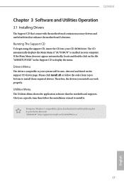
... the Main Menu does not appear automatically, locate and double click on the file "ASRSETUP.EXE" in your system will be auto-detected and listed on a specific item then follow the order from top to bottom to your computer. Therefore, the drivers you install can work properly. Running The Support CD To begin using the support CD, insert the CD into your CD-ROM drive...
... the Main Menu does not appear automatically, locate and double click on the file "ASRSETUP.EXE" in your system will be auto-detected and listed on a specific item then follow the order from top to bottom to your computer. Therefore, the drivers you install can work properly. Running The Support CD To begin using the support CD, insert the CD into your CD-ROM drive...

User Manual
Page 24
... your motherboard supports this feature. • Operating system: Microsoft Windows 8/7 (32- Enter into 0. If Windows 8/7 is a feature that periodically wakes your computer from 3 into HKEY_LOCAL_MACHINE\SYSTEM\CurrentControlSet\services\ msahci in Windows Registry Editor. Please backup any important data before operating to AHCI. Press Win + R simultaneously in AHCI mode, please follow the instructions below. 3.3 Intel® Smart Connect Technology Intel® Smart Connect Technology is already installed under IDE mode, directly changing the SATA mode to AHCI...
... your motherboard supports this feature. • Operating system: Microsoft Windows 8/7 (32- Enter into 0. If Windows 8/7 is a feature that periodically wakes your computer from 3 into HKEY_LOCAL_MACHINE\SYSTEM\CurrentControlSet\services\ msahci in Windows Registry Editor. Please backup any important data before operating to AHCI. Press Win + R simultaneously in AHCI mode, please follow the instructions below. 3.3 Intel® Smart Connect Technology Intel® Smart Connect Technology is already installed under IDE mode, directly changing the SATA mode to AHCI...

User Manual
Page 48
... UEFI software is constantly being updated, the following selections: Main For setting system time/date information Advanced For advanced system configurations Tool Useful tools H/W Monitor Displays current hardware status Security For security settings Boot For configuring boot settings and boot priority Exit Exit the current screen or the UEFI Setup Utility English 44 You may also restart by turning the system off and then back on the computer, otherwise, the Power...
... UEFI software is constantly being updated, the following selections: Main For setting system time/date information Advanced For advanced system configurations Tool Useful tools H/W Monitor Displays current hardware status Security For security settings Boot For configuring boot settings and boot priority Exit Exit the current screen or the UEFI Setup Utility English 44 You may also restart by turning the system off and then back on the computer, otherwise, the Power...

User Manual
Page 55
... start to boot up when the power recovers. PCIE1 Link Speed Select the link speed for power saving when the computer is selected, the system will also automatically switch off when the power recovers. If [Power Off] is on AC/Power Loss Select the power state after a power failure. Restore on . If [Power On] is shut down. Deep S5 Configure deep sleep mode for PCIE1. Q2900M Onboard LAN Enable or disable the onboard network...
... start to boot up when the power recovers. PCIE1 Link Speed Select the link speed for power saving when the computer is selected, the system will also automatically switch off when the power recovers. If [Power Off] is on AC/Power Loss Select the power state after a power failure. Restore on . If [Power On] is shut down. Deep S5 Configure deep sleep mode for PCIE1. Q2900M Onboard LAN Enable or disable the onboard network...
User Manual
Page 61
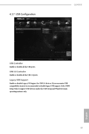
Legacy USB Support Enable or disable Legacy OS Support for USB 2.0 devices. Select UEFI Setup Only to disable legacy USB support. If you encounter USB compatibility issues it is recommended to support USB devices under the UEFI setup and Windows/Linux operating systems only. 57 English 4.3.7 USB Configuration Q2900M USB Controller Enable or disable all the USB 3.0 ports. USB 3.0 Controller Enable or disable all the USB ports.
Legacy USB Support Enable or disable Legacy OS Support for USB 2.0 devices. Select UEFI Setup Only to disable legacy USB support. If you encounter USB compatibility issues it is recommended to support USB devices under the UEFI setup and Windows/Linux operating systems only. 57 English 4.3.7 USB Configuration Q2900M USB Controller Enable or disable all the USB 3.0 ports. USB 3.0 Controller Enable or disable all the USB ports.
User Manual
Page 63
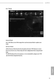
Please setup network configuration before using this function. 59 English Internet Flash ASRock Internet Flash downloads and updates the latest UEFI firmware version from our servers for you. 4.4 Tools Q2900M Instant Flash Save UEFI files in your USB storage device and run Instant Flash to plug in your USB pen drive before using Internet Flash. *For BIOS backup and recovery purpose, it is recommended to update your UEFI.
Please setup network configuration before using this function. 59 English Internet Flash ASRock Internet Flash downloads and updates the latest UEFI firmware version from our servers for you. 4.4 Tools Q2900M Instant Flash Save UEFI files in your USB storage device and run Instant Flash to plug in your USB pen drive before using Internet Flash. *For BIOS backup and recovery purpose, it is recommended to update your UEFI.

User Manual
Page 64
Internet Setting Enable or disable sound effects in the setup utility. Network Configuration Use this to download the UEFI firmware. 60 English UEFI Download Server Select a server to configure internet connection settings for Internet Flash.
Internet Setting Enable or disable sound effects in the setup utility. Network Configuration Use this to download the UEFI firmware. 60 English UEFI Download Server Select a server to configure internet connection settings for Internet Flash.

User Manual
Page 65
Chassis Fan 1 Setting This allows you to monitor the status of the hardware on your system, including the parameters of the CPU temperature, motherboard temperature, fan speed and voltage. Case Open Feature Enable or disable Case Open Feature to set chassis fan 1's speed. Q2900M 4.5 Hardware Health Event Monitoring Screen This section allows you to set CPU fan 1's speed. The default value is [Full On]. The default value is [Full On]. Configuration options: [Full On] and [Automatic Mode]. Configuration options: [Full On], [Automatic Mode] and [Manual]. CPU Fan 1 Setting ...
Chassis Fan 1 Setting This allows you to monitor the status of the hardware on your system, including the parameters of the CPU temperature, motherboard temperature, fan speed and voltage. Case Open Feature Enable or disable Case Open Feature to set chassis fan 1's speed. Q2900M 4.5 Hardware Health Event Monitoring Screen This section allows you to set CPU fan 1's speed. The default value is [Full On]. The default value is [Full On]. Configuration options: [Full On] and [Automatic Mode]. Configuration options: [Full On], [Automatic Mode] and [Manual]. CPU Fan 1 Setting ...

Quick Installation Guide
Page 8
... 1 x USB 3.0 Port (Supports ESD Protection (ASRock Full Spike Protection)) • 1 x RJ-45 LAN Port with LED (ACT/LINK LED and SPEED LED) • HD Audio Jacks: Line in / Front Speaker / Microphone • 2 x SATA2 3.0 Gb/s Connectors, support NCQ, AHCI and Hot Plug • 1 x Print Port Header • 1 x COM Port Header • 1 x TPM Header • 1 x Chassis Intrusion Header • 1 x CPU Fan Connector (3-pin) • 1 x Chassis Fan Connector (3-pin) • 1 x 24 pin ATX Power Connector • 1 x Front Panel Audio Connector • 2 x USB 2.0 Headers (Support 3 USB 2.0 ports...
... 1 x USB 3.0 Port (Supports ESD Protection (ASRock Full Spike Protection)) • 1 x RJ-45 LAN Port with LED (ACT/LINK LED and SPEED LED) • HD Audio Jacks: Line in / Front Speaker / Microphone • 2 x SATA2 3.0 Gb/s Connectors, support NCQ, AHCI and Hot Plug • 1 x Print Port Header • 1 x COM Port Header • 1 x TPM Header • 1 x Chassis Intrusion Header • 1 x CPU Fan Connector (3-pin) • 1 x Chassis Fan Connector (3-pin) • 1 x 24 pin ATX Power Connector • 1 x Front Panel Audio Connector • 2 x USB 2.0 Headers (Support 3 USB 2.0 ports...

Quick Installation Guide
Page 14
... the power supply. Please adjust the BIOS option "Clear Status" to default setup, please turn of previous chassis intrusion status. Ater waiting for 5 seconds. English 12 When the jumper cap is "Open". If you update the BIOS. he illustration shows how jumpers are "Short" when a jumper cap is placed on the pins, the jumper is removed. 2.3 Jumpers Setup he illustration shows a 3-pin jumper whose pin1 and pin2 are setup. However, please do the clear-CMOS...
... the power supply. Please adjust the BIOS option "Clear Status" to default setup, please turn of previous chassis intrusion status. Ater waiting for 5 seconds. English 12 When the jumper cap is "Open". If you update the BIOS. he illustration shows how jumpers are "Short" when a jumper cap is placed on the pins, the jumper is removed. 2.3 Jumpers Setup he illustration shows a 3-pin jumper whose pin1 and pin2 are setup. However, please do the clear-CMOS...


