User Manual
Page 2
... business, loss of data, interruption of business and the like), even if ASRock has been advised of the possibility of ASRock Inc. "Perchlorate Material-special handling may not cause harmful interference, and (2) this documentation. Disclaimer: Specifications and information contained in this motherboard contains Perchlorate, a toxic substance controlled in the documentation or product. CALIFORNIA...
... business, loss of data, interruption of business and the like), even if ASRock has been advised of the possibility of ASRock Inc. "Perchlorate Material-special handling may not cause harmful interference, and (2) this documentation. Disclaimer: Specifications and information contained in this motherboard contains Perchlorate, a toxic substance controlled in the documentation or product. CALIFORNIA...
User Manual
Page 3
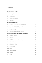
Contents Chapter 1 Introduction 1 1.1 Package Contents 1 1.2 Specifications 2 1.3 Motherboard Layout 6 1.4 I/O Panel 8 Chapter 2 Installation 9 2.1 Installing Memory Modules (SO-DIMM) 10 2.2 Expansion Slots (PCI Express Slots) 12 2.5 Jumpers Setup 13 2.6 Onboard Headers and Connectors 14 Chapter 3 Software and Utilities Operation 20 3.1 Installing Drivers 20 3.2 A-Tuning 21 3.3 Intel® Smart Connect Technology 23 3.5 ASRock Cloud 28 3.6 ASRock APP Shop 37 3.6.1 UI Overview 37 3.6.2 Apps 38 3.6.3 BIOS & Drivers 41 3.6.4 Setting 42 3.7 Start8 44
Contents Chapter 1 Introduction 1 1.1 Package Contents 1 1.2 Specifications 2 1.3 Motherboard Layout 6 1.4 I/O Panel 8 Chapter 2 Installation 9 2.1 Installing Memory Modules (SO-DIMM) 10 2.2 Expansion Slots (PCI Express Slots) 12 2.5 Jumpers Setup 13 2.6 Onboard Headers and Connectors 14 Chapter 3 Software and Utilities Operation 20 3.1 Installing Drivers 20 3.2 A-Tuning 21 3.3 Intel® Smart Connect Technology 23 3.5 ASRock Cloud 28 3.6 ASRock APP Shop 37 3.6.1 UI Overview 37 3.6.2 Apps 38 3.6.3 BIOS & Drivers 41 3.6.4 Setting 42 3.7 Start8 44
User Manual
Page 5
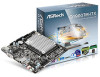
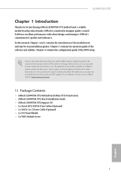
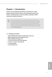
... step-by-step installation guides. Chapter 4 contains the configuration guide of the software and utilities. ASRock website http://www.asrock.com. 1.1 Package Contents • ASRock Q1900TM-ITX Motherboard (Mini-ITX Form Factor) • ASRock Q1900TM-ITX Quick Installation Guide • ASRock Q1900TM-ITX Support CD • 2 x Serial ATA (SATA) Data Cables (Optional) • 1 x SATA 1 to quality and endurance. If you require technical support...
... step-by-step installation guides. Chapter 4 contains the configuration guide of the software and utilities. ASRock website http://www.asrock.com. 1.1 Package Contents • ASRock Q1900TM-ITX Motherboard (Mini-ITX Form Factor) • ASRock Q1900TM-ITX Quick Installation Guide • ASRock Q1900TM-ITX Support CD • 2 x Serial ATA (SATA) Data Cables (Optional) • 1 x SATA 1 to quality and endurance. If you require technical support...
User Manual
Page 13
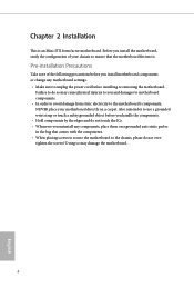
Q1900TM-ITX Chapter 2 Installation This is an Mini-ITX form factor motherboard. Also remember to use a grounded wrist strap or touch a safety grounded object before you handle the components. • Hold components by the edges and do ...not overtighten the screws! Failure to ensure that comes with the components. • When placing screws to secure the motherboard to the...
Q1900TM-ITX Chapter 2 Installation This is an Mini-ITX form factor motherboard. Also remember to use a grounded wrist strap or touch a safety grounded object before you handle the components. • Hold components by the edges and do ...not overtighten the screws! Failure to ensure that comes with the components. • When placing screws to secure the motherboard to the...

User Manual
Page 14
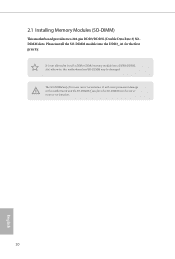
The SO-DIMM only fits in one correct orientation. 2.1 Installing Memory Modules (SO-DIMM) This motherboard provides two 204-pin DDR3/DDR3L (Double Data Rate 3) SODIMM slots. otherwise, this motherboard and SO-DIMM may be damaged. Please install the SO-DIMM module into the slot at incorrect orientation. 10 English It will cause permanent damage to install a DDR or DDR2 memory module into a DDR3/DDR3L slot; It is not allowed to the motherboard and the SO-DIMM if you force the SO-DIMM into the DDR3_A1 for the first priority.
The SO-DIMM only fits in one correct orientation. 2.1 Installing Memory Modules (SO-DIMM) This motherboard provides two 204-pin DDR3/DDR3L (Double Data Rate 3) SODIMM slots. otherwise, this motherboard and SO-DIMM may be damaged. Please install the SO-DIMM module into the slot at incorrect orientation. 10 English It will cause permanent damage to install a DDR or DDR2 memory module into a DDR3/DDR3L slot; It is not allowed to the motherboard and the SO-DIMM if you force the SO-DIMM into the DDR3_A1 for the first priority.

User Manual
Page 16
PCIe slot: PCIE1 (PCIe 2.0 x4 slot) is used for PCI Express x4 lane width cards. mini-PCIe slot: MINI_PCIE1 (mini-PCIe slot) is used for the card before you start the installation. Before installing an expansion card, please make necessary hardware settings for WiFi module. 12 English 2.2 Expansion Slots (PCI Express Slots) There is unplugged. Please read the documentation of the expansion card and make sure that the power supply is switched off or the power cord is 1 PCI Express slot and 1 mini PCI Express slot on this motherboard.
PCIe slot: PCIE1 (PCIe 2.0 x4 slot) is used for PCI Express x4 lane width cards. mini-PCIe slot: MINI_PCIE1 (mini-PCIe slot) is used for the card before you start the installation. Before installing an expansion card, please make necessary hardware settings for WiFi module. 12 English 2.2 Expansion Slots (PCI Express Slots) There is unplugged. Please read the documentation of the expansion card and make sure that the power supply is switched off or the power cord is 1 PCI Express slot and 1 mini PCI Express slot on this motherboard.
User Manual
Page 18
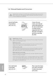
.... 11) 14 1 PLED- Note the positive and negative pins before connecting the cables. You may differ by chassis. PLED (System Power LED): Connect to the motherboard. Placing jumper caps over these headers and connectors. Press the reset switch to restart the computer if the computer freezes and fails to indicate the...
.... 11) 14 1 PLED- Note the positive and negative pins before connecting the cables. You may differ by chassis. PLED (System Power LED): Connect to the motherboard. Placing jumper caps over these headers and connectors. Press the reset switch to restart the computer if the computer freezes and fails to indicate the...
User Manual
Page 19
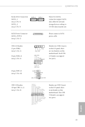
... panel, there is one USB 3.0 port on the I /O panel, there are two headers on this motherboard. This USB 3.0 header can support two ports. 1 GND P+ PUSB_PWR DUMMY GND P+ P- English 15 USB 2.0 ...Q1900TM-ITX Serial ATA2 Connectors (SATA_1: see p.5, No. 4) (SATA_2: see p.5, No. 3) SATA_2 SATA_1 SATA Power Connector (SATA_POW1) (see p.5, No. 8) 1 GND P- USB_PWR GND P+ PUSB_PWR 1 IntA_P_D+ IntA_P_DGND IntA_P_SSTX+ IntA_P_SSTXGND IntA_P_SSRX+ IntA_P_SSRXVbus 1 Vbus IntA_P_SSRXIntA_P_SSRX+ GND IntA_P_SSTXIntA_P_SSTX+ GND IntA_P_DIntA_P_D+ ID Besides one header on this motherboard...
... panel, there is one USB 3.0 port on the I /O panel, there are two headers on this motherboard. This USB 3.0 header can support two ports. 1 GND P+ PUSB_PWR DUMMY GND P+ P- English 15 USB 2.0 ...Q1900TM-ITX Serial ATA2 Connectors (SATA_1: see p.5, No. 4) (SATA_2: see p.5, No. 3) SATA_2 SATA_1 SATA Power Connector (SATA_POW1) (see p.5, No. 8) 1 GND P- USB_PWR GND P+ PUSB_PWR 1 IntA_P_D+ IntA_P_DGND IntA_P_SSTX+ IntA_P_SSTXGND IntA_P_SSRX+ IntA_P_SSRXVbus 1 Vbus IntA_P_SSRXIntA_P_SSRX+ GND IntA_P_SSTXIntA_P_SSTX+ GND IntA_P_DIntA_P_D+ ID Besides one header on this motherboard...
User Manual
Page 21
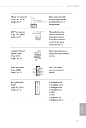
...) Backlight Control Header (8-pin BLT_VOL1) (see p.5, No. 10) FAN_SPEED_CONTROL CPU_FAN_SPEED +12V GND This motherboard provides a 4-Pin CPU fan (Quiet Fan) connector. CIR input +5VA Learn-in LED 1 +5VA IRTX GND This header can be used to the ground pin. Q1900TM-ITX Chassis Fan Connector (4-pin CHA_FAN1) (see p.5, No. 9) GND +12V CHA_FAN_SPEED FAN_SPEED_CONTROL Please...
...) Backlight Control Header (8-pin BLT_VOL1) (see p.5, No. 10) FAN_SPEED_CONTROL CPU_FAN_SPEED +12V GND This motherboard provides a 4-Pin CPU fan (Quiet Fan) connector. CIR input +5VA Learn-in LED 1 +5VA IRTX GND This header can be used to the ground pin. Q1900TM-ITX Chassis Fan Connector (4-pin CHA_FAN1) (see p.5, No. 9) GND +12V CHA_FAN_SPEED FAN_SPEED_CONTROL Please...
User Manual
Page 24
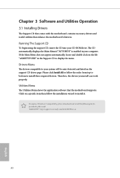
... menu. Please click Install All or follow the installation wizard to your computer. Utilities Menu The Utilities Menu shows the application software that enhance the motherboard's features. To improve Windows 7 compatibility, please download and install the following hot fix provided by Microsoft. Drivers Menu The drivers compatible to install it...": http://support.microsoft.com/kb/2720599/en-us 20 English Chapter 3 Software and Utilities Operation 3.1 Installing Drivers The Support CD that comes with the motherboard contains necessary drivers and useful utilities that the...
... menu. Please click Install All or follow the installation wizard to your computer. Utilities Menu The Utilities Menu shows the application software that enhance the motherboard's features. To improve Windows 7 compatibility, please download and install the following hot fix provided by Microsoft. Drivers Menu The drivers compatible to install it...": http://support.microsoft.com/kb/2720599/en-us 20 English Chapter 3 Software and Utilities Operation 3.1 Installing Drivers The Support CD that comes with the motherboard contains necessary drivers and useful utilities that the...
User Manual
Page 27
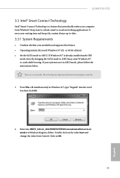
... IDE mode, directly changing the SATA mode to AHCI may cause Windows 8/7 to -date. 3.3.1 System Requirements • Confirm whether your motherboard supports this feature. • Operating system: Microsoft Windows 8/7 (32- Please backup any important data before operating to AHCI. Enter into ... state to refresh email or social networking applications. or 64-bit edition) • Set the SATA mode to avoid loss. 1. Q1900TM-ITX 3.3 Intel® Smart Connect Technology Intel® Smart Connect Technology is a feature that periodically wakes your computer from 3 into HKEY_LOCAL_MACHINE...
... IDE mode, directly changing the SATA mode to AHCI may cause Windows 8/7 to -date. 3.3.1 System Requirements • Confirm whether your motherboard supports this feature. • Operating system: Microsoft Windows 8/7 (32- Please backup any important data before operating to AHCI. Enter into ... state to refresh email or social networking applications. or 64-bit edition) • Set the SATA mode to avoid loss. 1. Q1900TM-ITX 3.3 Intel® Smart Connect Technology Intel® Smart Connect Technology is a feature that periodically wakes your computer from 3 into HKEY_LOCAL_MACHINE...
User Manual
Page 32
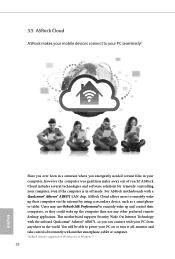
...supported on or turn it off mode. ASRock Cloud includes several technologies and software solutions for remotely controlling your PC seamlessly! Have you ever been in the world. For ASRock motherboards with another smartphone, tablet or computer. *ASRock Cloud is in off , monitor and ...take control of reach? This motherboard supports Security Wake On Internet Technology with the onboard Qualcomm® Atheros...
...supported on or turn it off mode. ASRock Cloud includes several technologies and software solutions for remotely controlling your PC seamlessly! Have you ever been in the world. For ASRock motherboards with another smartphone, tablet or computer. *ASRock Cloud is in off , monitor and ...take control of reach? This motherboard supports Security Wake On Internet Technology with the onboard Qualcomm® Atheros...
User Manual
Page 36
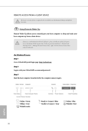
... and password. For Windows PC users: Step 1 Go to sleep and wake your host computer up from the list by the computer name you use a motherboard with your host computer to Orbweb.ME portal login page: http://orbweb.me Step 2 Log in with dual LAN ports, please disable one of Java...
... and password. For Windows PC users: Step 1 Go to sleep and wake your host computer up from the list by the computer name you use a motherboard with your host computer to Orbweb.ME portal login page: http://orbweb.me Step 2 Log in with dual LAN ports, please disable one of Java...
User Manual
Page 41
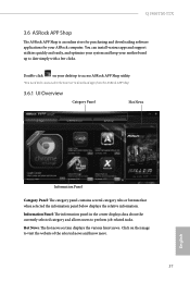
...contains several category tabs or buttons that when selected the information panel below displays the relative information. Click on your desktop to access ASRock APP Shop utility. *You need to be connected to the Internet to visit the website of the selected news and know more... the currently selected category and allows users to date simply with a few clicks. Q1900TM-ITX 3.6 ASRock APP Shop The ASRock APP Shop is an online store for purchasing and downloading software applications for your motherboard up to perform job-related tasks. You can install various apps and support utilities...
...contains several category tabs or buttons that when selected the information panel below displays the relative information. Click on your desktop to access ASRock APP Shop utility. *You need to be connected to the Internet to visit the website of the selected news and know more... the currently selected category and allows users to date simply with a few clicks. Q1900TM-ITX 3.6 ASRock APP Shop The ASRock APP Shop is an online store for purchasing and downloading software applications for your motherboard up to perform job-related tasks. You can install various apps and support utilities...

User Manual
Page 67
Q1900TM-ITX 4.5 Hardware Health Event Monitoring Screen This section allows you to set CPU temperatures and assign a respective fan speed for each temperature. CPU Fan 1 Type Select ... a fan mode for Chassis Fan 1, or choose Customize to monitor the status of the hardware on your system, including the parameters of the CPU temperature, motherboard temperature, fan speed and voltage. CHA Fan 1 Type Select 3pin or 4pin fan type.
Q1900TM-ITX 4.5 Hardware Health Event Monitoring Screen This section allows you to set CPU temperatures and assign a respective fan speed for each temperature. CPU Fan 1 Type Select ... a fan mode for Chassis Fan 1, or choose Customize to monitor the status of the hardware on your system, including the parameters of the CPU temperature, motherboard temperature, fan speed and voltage. CHA Fan 1 Type Select 3pin or 4pin fan type.

Quick Installation Guide
Page 1
... Version 1.0 Published May 2014 Copyright©2014 ASRock INC. Copyright Notice: No part of this documentation may cause undesired operation. This device complies with Part 15 of HDMI Licensing LLC in this motherboard contains Perchlorate, a toxic substance controlled in the... interference received, including interference that may apply, see www.dtsc.ca.gov/hazardouswaste/ perchlorate" ASRock Website: http://www.asrock.com ASRock assumes no event shall ASRock, its directors, officers, employees, or agents be registered trademarks or copyrights of their respective companies...
... Version 1.0 Published May 2014 Copyright©2014 ASRock INC. Copyright Notice: No part of this documentation may cause undesired operation. This device complies with Part 15 of HDMI Licensing LLC in this motherboard contains Perchlorate, a toxic substance controlled in the... interference received, including interference that may apply, see www.dtsc.ca.gov/hazardouswaste/ perchlorate" ASRock Website: http://www.asrock.com ASRock assumes no event shall ASRock, its directors, officers, employees, or agents be registered trademarks or copyrights of their respective companies...
Quick Installation Guide
Page 5
..., please do not overtighten the screws! Chapter 2 Installation This is an Mini-ITX form factor motherboard. Doing so may cause physical injuries to you and damages to motherboard components. • In order to avoid damage from static electricity to the motherboard's components, NEVER place your chassis to ensure that comes with the components. •...
..., please do not overtighten the screws! Chapter 2 Installation This is an Mini-ITX form factor motherboard. Doing so may cause physical injuries to you and damages to motherboard components. • In order to avoid damage from static electricity to the motherboard's components, NEVER place your chassis to ensure that comes with the components. •...
Quick Installation Guide
Page 6
... this documentation will be subject to this documentation occur, the updated version will be updated, the content of this motherboard, please visit our website for purchasing ASRock Q1900TM-ITX motherboard, a reliable motherboard produced under ASRock's consistently stringent quality control. Q1900TM-ITX Chapter 1 Introduction Thank you for specific information about the model you require technical support related to change without...
... this documentation will be subject to this documentation occur, the updated version will be updated, the content of this motherboard, please visit our website for purchasing ASRock Q1900TM-ITX motherboard, a reliable motherboard produced under ASRock's consistently stringent quality control. Q1900TM-ITX Chapter 1 Introduction Thank you for specific information about the model you require technical support related to change without...
Quick Installation Guide
Page 11
It will cause permanent damage to install a DDR or DDR2 memory module into the slot at incorrect orientation. 10 English It is not allowed to the motherboard and the SO-DIMM if you force the SO-DIMM into a DDR3/DDR3L slot; Please install the SO-DIMM module into the DDR3_A1 for the first priority. The SO-DIMM only fits in one correct orientation. 2.1 Installing Memory Modules (SO-DIMM) This motherboard provides two 204-pin DDR3/DDR3L (Double Data Rate 3) SODIMM slots. otherwise, this motherboard and SO-DIMM may be damaged.
It will cause permanent damage to install a DDR or DDR2 memory module into the slot at incorrect orientation. 10 English It is not allowed to the motherboard and the SO-DIMM if you force the SO-DIMM into a DDR3/DDR3L slot; Please install the SO-DIMM module into the DDR3_A1 for the first priority. The SO-DIMM only fits in one correct orientation. 2.1 Installing Memory Modules (SO-DIMM) This motherboard provides two 204-pin DDR3/DDR3L (Double Data Rate 3) SODIMM slots. otherwise, this motherboard and SO-DIMM may be damaged.
Quick Installation Guide
Page 13
Please read the documentation of the expansion card and make sure that the power supply is switched off or the power cord is used for WiFi module. 12 English PCIe slot: PCIE1 (PCIe 2.0 x4 slot) is unplugged. Before installing an expansion card, please make necessary hardware settings for the card before you start the installation. 2.2 Expansion Slots (PCI Express Slots) There is used for PCI Express x4 lane width cards. mini-PCIe slot: MINI_PCIE1 (mini-PCIe slot) is 1 PCI Express slot and 1 mini PCI Express slot on this motherboard.
Please read the documentation of the expansion card and make sure that the power supply is switched off or the power cord is used for WiFi module. 12 English PCIe slot: PCIE1 (PCIe 2.0 x4 slot) is unplugged. Before installing an expansion card, please make necessary hardware settings for the card before you start the installation. 2.2 Expansion Slots (PCI Express Slots) There is used for PCI Express x4 lane width cards. mini-PCIe slot: MINI_PCIE1 (mini-PCIe slot) is 1 PCI Express slot and 1 mini PCI Express slot on this motherboard.

