User Manual
Page 3
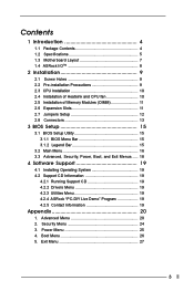
...Advanced Menu 20 2. Boot Menu 26 5. Contents 1 Introduction 4 1.1 Package Contents 4 1.2 Specifications 5 1.3 Motherboard Layout 7 1.4 ASRock I/OTM 8 2 Installation 9 2.1 Screw Holes 9 2.2 Pre-installation Precautions 9 2.3 CPU Installation 10 2.4 Installation of Heatsink and CPU fan 10 2.5 Installation of Memory Modules (DIMM 11 2.6 Expansion Slots 11 2.7 Jumpers Setup 12 2.8 Connectors 13 3 BIOS Setup 15 3.1 BIOS Setup Utility 15 3.1.1 BIOS Menu Bar 15 3.1.2 Legend Bar 15 3.2 Main Menu 16 3.3 Advanced, Security, Power, Boot, and Exit Menus ..... 18 4 Software Support 19...
...Advanced Menu 20 2. Boot Menu 26 5. Contents 1 Introduction 4 1.1 Package Contents 4 1.2 Specifications 5 1.3 Motherboard Layout 7 1.4 ASRock I/OTM 8 2 Installation 9 2.1 Screw Holes 9 2.2 Pre-installation Precautions 9 2.3 CPU Installation 10 2.4 Installation of Heatsink and CPU fan 10 2.5 Installation of Memory Modules (DIMM 11 2.6 Expansion Slots 11 2.7 Jumpers Setup 12 2.8 Connectors 13 3 BIOS Setup 15 3.1 BIOS Setup Utility 15 3.1.1 BIOS Menu Bar 15 3.1.2 Legend Bar 15 3.2 Main Menu 16 3.3 Advanced, Security, Power, Boot, and Exit Menus ..... 18 4 Software Support 19...

User Manual
Page 4
...-step installation guide for new DIY system builders. ASRock website http://www.asrock.com 1.1 Package Contents ASRock P4VX4 motherboard (ATX form factor: 12.0" x 7.5", 30.5 x 19.0 cm) ASRock P4VX4 Quick Setup Guide ASRock P4VX4 Support CD 1 Cable for IDE devices (1 x ATA 66/100/133) 1 Cable for purchasing ASRock P4VX4 motherboard, a reliable motherboard produced under ASRock's consistently stringent quality control. Because the motherboard specifications and the BIOS software might be updated, the content of this manual contain introduction of this manual occur, the updated version will...
...-step installation guide for new DIY system builders. ASRock website http://www.asrock.com 1.1 Package Contents ASRock P4VX4 motherboard (ATX form factor: 12.0" x 7.5", 30.5 x 19.0 cm) ASRock P4VX4 Quick Setup Guide ASRock P4VX4 Support CD 1 Cable for IDE devices (1 x ATA 66/100/133) 1 Cable for purchasing ASRock P4VX4 motherboard, a reliable motherboard produced under ASRock's consistently stringent quality control. Because the motherboard specifications and the BIOS software might be updated, the content of this manual contain introduction of this manual occur, the updated version will...

User Manual
Page 5
...with PCI Specification 2.2 AGP slot: 1 AGP slot, supports 1.5V, 8X/4X AGP card (see CAUTION 1); CPU overheat shutdown to 4 IDE devices Floppy Port: Supports 1 floppy disk drive Audio: 5.1 channels AC'97 Audio LAN: Speed: 802.3u (10/100 Ethernet), supports Wake-On-LAN Hardware Monitor: CPU temperature sensing (ASRock U-COP); CPU fan tachometer; 1.2 Specifications Platform: ATX form factor (12.0" x 7.5", 30.5 x 19.0 cm) CPU: Socket 478 for 3 DDR DIMM slots, Max. 2GB; PC2700 for 2 DDR DIMM slot, Max. 1GB IDE: IDE1: ATA 133 / Ultra DMA Mode 6; Chassis temperature sensing...
...with PCI Specification 2.2 AGP slot: 1 AGP slot, supports 1.5V, 8X/4X AGP card (see CAUTION 1); CPU overheat shutdown to 4 IDE devices Floppy Port: Supports 1 floppy disk drive Audio: 5.1 channels AC'97 Audio LAN: Speed: 802.3u (10/100 Ethernet), supports Wake-On-LAN Hardware Monitor: CPU temperature sensing (ASRock U-COP); CPU fan tachometer; 1.2 Specifications Platform: ATX form factor (12.0" x 7.5", 30.5 x 19.0 cm) CPU: Socket 478 for 3 DDR DIMM slots, Max. 2GB; PC2700 for 2 DDR DIMM slot, Max. 1GB IDE: IDE1: ATA 133 / Ultra DMA Mode 6; Chassis temperature sensing...
User Manual
Page 6
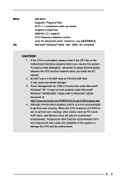
... / 2000 / XP compliant CAUTION! 1. When the CPU frequency of the system or damage the CPU and the motherboard. 6 If the CPU is overheated, please check if the CPU fan on P4VX4's AGP slot! ACPI 1.1 compliance wake up events; Supports "Plug and Play"; SMBIOS 2.3.1 support; It may not work properly under Microsoft® Windows® XP. Frequencies other clocks, such as PCI clock, AGP clock, and Memory clock will also be overclocked proportionally. BIOS: OS: AMI...
... / 2000 / XP compliant CAUTION! 1. When the CPU frequency of the system or damage the CPU and the motherboard. 6 If the CPU is overheated, please check if the CPU fan on P4VX4's AGP slot! ACPI 1.1 compliance wake up events; Supports "Plug and Play"; SMBIOS 2.3.1 support; It may not work properly under Microsoft® Windows® XP. Frequencies other clocks, such as PCI clock, AGP clock, and Memory clock will also be overclocked proportionally. BIOS: OS: AMI...

User Manual
Page 9
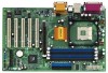
...-tighten the screws! Failure to do so may cause physical injuries to ensure that comes with the component. 9 Make sure to do not touch the ICs. 4. Chapter 2 Installation P4VX4 is an ATX form factor (12.0" x 7.5", 30.5 x 19.0 cm) motherboard. Hold components by circles to secure the motherboard to the chassis. Failure to unplug the power cord before installing or removing the motherboard.
...-tighten the screws! Failure to do so may cause physical injuries to ensure that comes with the component. 9 Make sure to do not touch the ICs. 4. Chapter 2 Installation P4VX4 is an ATX form factor (12.0" x 7.5", 30.5 x 19.0 cm) motherboard. Hold components by circles to secure the motherboard to the chassis. Failure to unplug the power cord before installing or removing the motherboard.

User Manual
Page 13
... USB ports are NOT jumpers. This connector supports an optional wireless transmitting and receiving infrared module. 13 DO NOT place jumper caps over these connectors. Connector FDD connector (33-pin FLOPPY1) (see p.7 item 8) PIN1 IDE1 PIN1 IDE2 connect the blue end to the motherboard connect the black end to the IDE devices 80-Pin ATA 100/133 cable Note: To optimize compatibility and performance, please connect your hard disk drive to the primary IDE connector...
... USB ports are NOT jumpers. This connector supports an optional wireless transmitting and receiving infrared module. 13 DO NOT place jumper caps over these connectors. Connector FDD connector (33-pin FLOPPY1) (see p.7 item 8) PIN1 IDE1 PIN1 IDE2 connect the blue end to the motherboard connect the black end to the IDE devices 80-Pin ATA 100/133 cable Note: To optimize compatibility and performance, please connect your hard disk drive to the primary IDE connector...

User Manual
Page 14
... from sound sources such as a CD-ROM, DVD-ROM, TV tuner card, or MPEG card. GND Connect the fan cable to the +12V connector matching the black CHA_FAN_SPEED wire to the ground pin. ATX power connector (20-pin ATXPWR1) (see p.7 item 20) GND +5VA This is an interface for front BACKOUT-R panel audio cable that allows BACKOUT-L convenient connection and 1 control of audio devices. Front panel audio connector (9-pin AUDIO1) (see p.7 item 1) Connect an ATX power supply to the connector. 14 O U T- L GND A U D - A U D - CPU fan connector (3-pin...
... from sound sources such as a CD-ROM, DVD-ROM, TV tuner card, or MPEG card. GND Connect the fan cable to the +12V connector matching the black CHA_FAN_SPEED wire to the ground pin. ATX power connector (20-pin ATXPWR1) (see p.7 item 20) GND +5VA This is an interface for front BACKOUT-R panel audio cable that allows BACKOUT-L convenient connection and 1 control of audio devices. Front panel audio connector (9-pin AUDIO1) (see p.7 item 1) Connect an ATX power supply to the connector. 14 O U T- L GND A U D - A U D - CPU fan connector (3-pin...

User Manual
Page 15
... POWER Configures Power Management features BOOT Configures the default system device that is a legend bar. Chapter 3 BIOS Setup 3.1 BIOS Setup Utility This section explains how to use the BIOS Setup Utility to enter the BIOS Setup Utility, otherwise, POST continues with its various sub-menus and select among the predetermined choices. You may also restart by pressing the reset button on the motherboard stores the BIOS Setup Utility. Please press during the Power-On-Self-Test (POST) to configure your screen. 3.1.1 BIOS Menu...
... POWER Configures Power Management features BOOT Configures the default system device that is a legend bar. Chapter 3 BIOS Setup 3.1 BIOS Setup Utility This section explains how to use the BIOS Setup Utility to enter the BIOS Setup Utility, otherwise, POST continues with its various sub-menus and select among the predetermined choices. You may also restart by pressing the reset button on the motherboard stores the BIOS Setup Utility. Please press during the Power-On-Self-Test (POST) to configure your screen. 3.1.1 BIOS Menu...
User Manual
Page 16
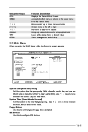
... field Loads all the setup items to default value Saves changes and exits Setup 3.2 Main Menu When you enter the BIOS Setup Utility, the following screen appears. IDE Devices Use this to set the type of floppy drives installed. Floppy Drives Use this to configure IDE devices. 16 Use keys to move between the Month, Day and Year fields. Main Advanced System Date System Time Floppy Drives IDE Devices BIOS Version Processor Type Processor Speed Cache Size Microcode Update Total Memory DDR1 DDR2 DDR3 DDR4 AMIBIOS SETUP UTILITY - System Time [Hour:Minute:Second] Set the...
... field Loads all the setup items to default value Saves changes and exits Setup 3.2 Main Menu When you enter the BIOS Setup Utility, the following screen appears. IDE Devices Use this to set the type of floppy drives installed. Floppy Drives Use this to configure IDE devices. 16 Use keys to move between the Month, Day and Year fields. Main Advanced System Date System Time Floppy Drives IDE Devices BIOS Version Processor Type Processor Speed Cache Size Microcode Update Total Memory DDR1 DDR2 DDR3 DDR4 AMIBIOS SETUP UTILITY - System Time [Hour:Minute:Second] Set the...

User Manual
Page 17
... BIOS Setup automatically fills in whcih the hard disk drive field will display the size of the hard disk drive that you have the correct configuration information supplied by the drive manufacturer. Main AMIBIOS SETUP UTILITY - Make sure to manually enter the number of the IDE device, first, please select "IDE Devices" on this sub-menu. Below are the configuration options. Incorrect settings may cause the system to fail to recognize the installed hard disk. [Auto]: Select [Auto] to manually enter the IDE hard disk drive parameters...
... BIOS Setup automatically fills in whcih the hard disk drive field will display the size of the hard disk drive that you have the correct configuration information supplied by the drive manufacturer. Main AMIBIOS SETUP UTILITY - Make sure to manually enter the number of the IDE device, first, please select "IDE Devices" on this sub-menu. Below are the configuration options. Incorrect settings may cause the system to fail to recognize the installed hard disk. [Auto]: Select [Auto] to manually enter the IDE hard disk drive parameters...

User Manual
Page 18
... and Windows; Set to [Disabled] to suppress Ultra DMA c ap ability. 3.3 Advanced, Security, Power, Boot, and Exit Menus Detailed descriptions of cylinders. LBA Mode This allows user to disable the LBA mode. Fast Programmed I/O Modes This allows user to set the PIO mode to enhance hard disk performance by the BIOS based on the drive information you entered. [CD/DVD]: This is used for IDE CD/DVD drives. [ARMD]: This is used to configure the...
... and Windows; Set to [Disabled] to suppress Ultra DMA c ap ability. 3.3 Advanced, Security, Power, Boot, and Exit Menus Detailed descriptions of cylinders. LBA Mode This allows user to disable the LBA mode. Fast Programmed I/O Modes This allows user to set the PIO mode to enhance hard disk performance by the BIOS based on the drive information you entered. [CD/DVD]: This is used for IDE CD/DVD drives. [ARMD]: This is used to configure the...
User Manual
Page 19
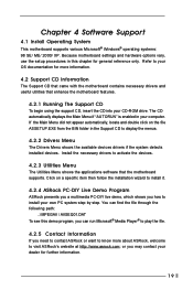
...; Windows® operating systems: 98 SE/ ME/ 2000/ XP. Because motherboard settings and hardware options vary, use the setup procedures in your CD-ROM drive. or you need to contact ASRock or want to activate the devices. 4.2.3 Utilities Menu The Utilities Menu shows the applications software that enhance the motherboard features. 4.2.1 Running The Support CD To begin using the support CD, insert the CD into your computer. Install the necessary drivers...
...; Windows® operating systems: 98 SE/ ME/ 2000/ XP. Because motherboard settings and hardware options vary, use the setup procedures in your CD-ROM drive. or you need to contact ASRock or want to activate the devices. 4.2.3 Utilities Menu The Utilities Menu shows the applications software that enhance the motherboard features. 4.2.1 Running The Support CD To begin using the support CD, insert the CD into your computer. Install the necessary drivers...
User Manual
Page 20
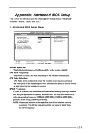
... installed memory module(s). NOTE: Please pay attention to enable or disable the feature of the installed processor. Whether the option is open or locked is selected, the motherboard will introduce you the following BIOS Setup menus: "Advanced," "Security," "Power," "Boot," and "Exit." 1. DRAM Frequency: If [Auto] is determined by the installed processor. Chipset Configuration Resource Configuration Peripheral Configuration System Hardware Monitor F1:Help Esc:Exit :Select Item :Select Menu +/-:Change Values Enter:Select Sub-Menu F9:Setup Defaults...
... installed memory module(s). NOTE: Please pay attention to enable or disable the feature of the installed processor. Whether the option is open or locked is selected, the motherboard will introduce you the following BIOS Setup menus: "Advanced," "Security," "Power," "Boot," and "Exit." 1. DRAM Frequency: If [Auto] is determined by the installed processor. Chipset Configuration Resource Configuration Peripheral Configuration System Hardware Monitor F1:Help Esc:Exit :Select Item :Select Menu +/-:Change Values Enter:Select Sub-Menu F9:Setup Defaults...

User Manual
Page 21
...support. VERSION 3.31a Chipset Configuration [ Setup Help ] AGP Mode AGP Aperture Size AGP Fast Write PCI Delay Transaction USB Controller USB Device Legacy Support DRAM CAS# Latency Hyper-Threading Technology Auto 64MB Disabled Disabled Enabled Disabled Auto Auto to enable or disable the feature of memory accessing. If the installed AGP card is recommended to [4X] as the AGP mode. PCI Delay Transaction: Enable PCI Delay Transaction feature will be set to [Auto] automatically. etc. This option will free the PCI Bus when the CPU is accessing 8-bit ISA cards. Chipset...
...support. VERSION 3.31a Chipset Configuration [ Setup Help ] AGP Mode AGP Aperture Size AGP Fast Write PCI Delay Transaction USB Controller USB Device Legacy Support DRAM CAS# Latency Hyper-Threading Technology Auto 64MB Disabled Disabled Enabled Disabled Auto Auto to enable or disable the feature of memory accessing. If the installed AGP card is recommended to [4X] as the AGP mode. PCI Delay Transaction: Enable PCI Delay Transaction feature will be set to [Auto] automatically. etc. This option will free the PCI Bus when the CPU is accessing 8-bit ISA cards. Chipset...

User Manual
Page 22
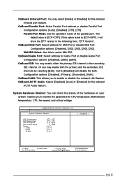
... Configuration [ Setup Help ] OnBoard FDC OnBoard Serial Port OnBoard Infrared Port OnBoard Parallel Port Parallel Port Mode EPP Version Parallel Port IRQ Parallel Port DMA Channel OnBoard Midi Port Midi IRQ Select OnBoard Game Port OnBoard IDE OnBoard LAN OnBoard AC' 97 Audio Auto Auto Disabled Auto ECP + EPP 1.9 Auto Auto Disabled 5 200h Both Enabled Auto to select PCI clocks. It is 32. F1:Help Esc:Previous Menu :Select Item +/-:Change Values Enter:Select Sub-Menu F9:Setup Defaults F10:Save & Exit OnBoard FDC: Use this to enable or disable floppy drive controller...
... Configuration [ Setup Help ] OnBoard FDC OnBoard Serial Port OnBoard Infrared Port OnBoard Parallel Port Parallel Port Mode EPP Version Parallel Port IRQ Parallel Port DMA Channel OnBoard Midi Port Midi IRQ Select OnBoard Game Port OnBoard IDE OnBoard LAN OnBoard AC' 97 Audio Auto Auto Disabled Auto ECP + EPP 1.9 Auto Auto Disabled 5 200h Both Enabled Auto to select PCI clocks. It is 32. F1:Help Esc:Previous Menu :Select Item +/-:Change Values Enter:Select Sub-Menu F9:Setup Defaults F10:Save & Exit OnBoard FDC: Use this to enable or disable floppy drive controller...
User Manual
Page 23
The default value is set to enable or disable the onboard LAN feature. Midi IRQ Select: Use this to [Disabled] will show the EPP version in the following item, "EPP Version". OnBoard LAN: This allows you to monitor the parameters for CPU temperature, Motherboard temperature, CPU fan speed, and critical voltage. OnBoard Infrared Port: You may select [Enable] or [Disabled] for the onboard AC'97 Audio feature. OnBoard IDE: You may enable both . System Hardware Monitor: You can check the status of...
The default value is set to enable or disable the onboard LAN feature. Midi IRQ Select: Use this to [Disabled] will show the EPP version in the following item, "EPP Version". OnBoard LAN: This allows you to monitor the parameters for CPU temperature, Motherboard temperature, CPU fan speed, and critical voltage. OnBoard Infrared Port: You may select [Enable] or [Disabled] for the onboard AC'97 Audio feature. OnBoard IDE: You may enable both . System Hardware Monitor: You can check the status of...

User Manual
Page 24
... Sub-Menu F9:Setup Defaults F10:Save & Exit Supervisor Password: This field shows the status of the User Password. [Clear]: No password has been set. [Set]: User password has been set . If you already have a password, you must enter your current password first in order to set User Password. If [Setup] option is selected, the "Password Check" is performed before BIOS setup. Security Setup Menu Main Advanced AMIBIOS SETUP UTILITY - VERSION 3.31a Security Power Boot Exit Supervisor Password User Password Set Supervisor Password Set User Password Clear Clear [ Enter ] [ Enter...
... Sub-Menu F9:Setup Defaults F10:Save & Exit Supervisor Password: This field shows the status of the User Password. [Clear]: No password has been set. [Set]: User password has been set . If you already have a password, you must enter your current password first in order to set User Password. If [Setup] option is selected, the "Password Check" is performed before BIOS setup. Security Setup Menu Main Advanced AMIBIOS SETUP UTILITY - VERSION 3.31a Security Power Boot Exit Supervisor Password User Password Set Supervisor Password Set User Password Clear Clear [ Enter ] [ Enter...

User Manual
Page 25
...-off mode. RTC Alarm Power On: Use this to enable or disable PCI devices to set the power state after an unexpected AC / Power loss. VERSION 3.31a Security Power Boot Exit Restore on AC/Power Loss: This allows you desire. 25 PS/2 Keyboard Power On: Use this to enable or disable Ring-in signals to turn on the system. F1:Help Esc:Exit :Select Item :Select Menu +/-:Change Values Enter:Select Sub-Menu F9:Setup Defaults...
...-off mode. RTC Alarm Power On: Use this to enable or disable PCI devices to set the power state after an unexpected AC / Power loss. VERSION 3.31a Security Power Boot Exit Restore on AC/Power Loss: This allows you desire. 25 PS/2 Keyboard Power On: Use this to enable or disable Ring-in signals to turn on the system. F1:Help Esc:Exit :Select Item :Select Menu +/-:Change Values Enter:Select Sub-Menu F9:Setup Defaults...

User Manual
Page 26
...]. Boot Setup Menu Main Advanced AMIBIOS SETUP UTILITY - Boot From Network: Use this is enabled, it will speed up the boot-up to enable or disable "boot from network" feature. VERSION 3.31a Security Power Boot Exit Quick Boot Mode Boot Up Num-Lock Boot To OS/2 Boot From Network Enabled On No Disabled [ Setup Help ] to set the boot device priority. 26 Boot Up Num-Lock: If this to OS/2 operating system. Boot Device Priority: This allows you to enable or disable the quick boot mode. The default value...
...]. Boot Setup Menu Main Advanced AMIBIOS SETUP UTILITY - Boot From Network: Use this is enabled, it will speed up the boot-up to enable or disable "boot from network" feature. VERSION 3.31a Security Power Boot Exit Quick Boot Mode Boot Up Num-Lock Boot To OS/2 Boot From Network Enabled On No Disabled [ Setup Help ] to set the boot device priority. 26 Boot Up Num-Lock: If this to OS/2 operating system. Boot Device Priority: This allows you to enable or disable the quick boot mode. The default value...

User Manual
Page 27
... any changes to the settings. Exit Discarding Changes: After you enter the sub-menu, the message "Save current settings and exit" will appear. If you press , you enter the sub-menu, the message "Load setup original values" will exit the BIOS Setup Utility without saving changes" will appear. VERSION 3.31a Security Power Boot Exit Exit Saving Changes Exit Discarding Changes Load Default Settings Discard Changes [ Enter ] [ Enter ] [ Enter ] [ Enter ] [ Setup Help ] Exits and saves the changes in CMOS RAM. Discard Changes: After...
... any changes to the settings. Exit Discarding Changes: After you enter the sub-menu, the message "Save current settings and exit" will appear. If you press , you enter the sub-menu, the message "Load setup original values" will exit the BIOS Setup Utility without saving changes" will appear. VERSION 3.31a Security Power Boot Exit Exit Saving Changes Exit Discarding Changes Load Default Settings Discard Changes [ Enter ] [ Enter ] [ Enter ] [ Enter ] [ Setup Help ] Exits and saves the changes in CMOS RAM. Discard Changes: After...


