User Manual
Page 3
... Menu 32 4. Exit Menu 34 3 Security Setup Menu 31 3. Contents 1 Introduction 4 1.1 Package Contents 4 1.2 Specifications 5 1.3 Motherboard Layout (P4S55FX 7 1.4 Motherboard Layout (P4S55FX 8 1.5 ASRock I/O PlusTM (P4S55FX+/ P4S55FX 9 2 Installation 10 Pre-installation Precautions 10 2.1 CPU Installation 11 2.2 Installation of CPU Fan and Heatsink 11 2.3 Installation of Memory Modules... CD Information 25 4.2.1 Running Support CD 25 4.2.2 Drivers Menu 25 4.2.3 Utilities Menu 25 4.2.4 ASRock "PC-DIY Live Demo" Program 25 4.2.5 Contact Information 25 Appendix 26 1.
... Menu 32 4. Exit Menu 34 3 Security Setup Menu 31 3. Contents 1 Introduction 4 1.1 Package Contents 4 1.2 Specifications 5 1.3 Motherboard Layout (P4S55FX 7 1.4 Motherboard Layout (P4S55FX 8 1.5 ASRock I/O PlusTM (P4S55FX+/ P4S55FX 9 2 Installation 10 Pre-installation Precautions 10 2.1 CPU Installation 11 2.2 Installation of CPU Fan and Heatsink 11 2.3 Installation of Memory Modules... CD Information 25 4.2.1 Running Support CD 25 4.2.2 Drivers Menu 25 4.2.3 Utilities Menu 25 4.2.4 ASRock "PC-DIY Live Demo" Program 25 4.2.5 Contact Information 25 Appendix 26 1.
User Manual
Page 4
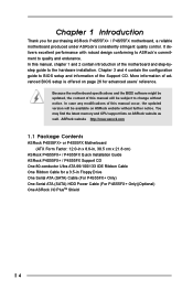
... guide to the hardware installation. ASRock website http://www.asrock.com 1.1 Package Contents ASRock P4S55FX+ or P4S55FX Motherboard (ATX Form Factor: 12.0-in x 8.6-in, 30.5 cm x 21.8 cm) ASRock P4S55FX+ / P4S55FX Quick Installation Guide ASRock P4S55FX+ / P4S55FX Support CD One 80-conductor Ultra ATA 66/100/133 IDE Ribbon Cable One Ribbon Cable for purchasing ASRock P4S55FX+ / P4S55FX motherboard, a reliable motherboard produced under ASRock's consistently stringent quality control...
... guide to the hardware installation. ASRock website http://www.asrock.com 1.1 Package Contents ASRock P4S55FX+ or P4S55FX Motherboard (ATX Form Factor: 12.0-in x 8.6-in, 30.5 cm x 21.8 cm) ASRock P4S55FX+ / P4S55FX Quick Installation Guide ASRock P4S55FX+ / P4S55FX Support CD One 80-conductor Ultra ATA 66/100/133 IDE Ribbon Cable One Ribbon Cable for purchasing ASRock P4S55FX+ / P4S55FX motherboard, a reliable motherboard produced under ASRock's consistently stringent quality control...

User Manual
Page 5
...6 Supports up to 4 IDE devices Serial ATA: 2 SATA connectors Supports up to 1.5Gb/s data transfer rate (SATA is only available on P4S55FX+ Motherboard) Floppy Port: Supports up to 2 floppy disk drives Audio: 5.1 channels AC'97 Audio LAN: Speed: 802.3u (10/100 Ethernet), supports... Wake-On-LAN Hardware Monitor: CPU temperature sensing Chassis temperature sensing CPU overheat shutdown to protect CPU life (ASRock U-COP)(see CAUTION 2) CPU fan tachometer Chassis fan tachometer Voltage monitoring: +12V, +5V, +3V, Vcore PCI slots: 5 slots with PCI...
...6 Supports up to 4 IDE devices Serial ATA: 2 SATA connectors Supports up to 1.5Gb/s data transfer rate (SATA is only available on P4S55FX+ Motherboard) Floppy Port: Supports up to 2 floppy disk drives Audio: 5.1 channels AC'97 Audio LAN: Speed: 802.3u (10/100 Ethernet), supports... Wake-On-LAN Hardware Monitor: CPU temperature sensing Chassis temperature sensing CPU overheat shutdown to protect CPU life (ASRock U-COP)(see CAUTION 2) CPU fan tachometer Chassis fan tachometer Voltage monitoring: +12V, +5V, +3V, Vcore PCI slots: 5 slots with PCI...
User Manual
Page 6
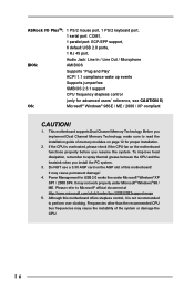
...of the system or damage the CPU. 6 It may cause the instability of this motherboard offers stepless control, it is overheated, please check if the CPU fan on the motherboard functions properly before you install the PC system. 3. Power Management for proper installation....under Microsoft® Windows® 98 / ME. It may not work properly under Microsoft® Windows® XP SP1 / 2000 SP4. This motherboard supports Dual Channel Memory Technology. ASRock I/O PlusTM: 1 PS/2 mouse port, 1 PS/2 keyboard port, 1 serial port: COM1, 1 parallel port: ECP/EPP support, 6 default ...
...of the system or damage the CPU. 6 It may cause the instability of this motherboard offers stepless control, it is overheated, please check if the CPU fan on the motherboard functions properly before you install the PC system. 3. Power Management for proper installation....under Microsoft® Windows® 98 / ME. It may not work properly under Microsoft® Windows® XP SP1 / 2000 SP4. This motherboard supports Dual Channel Memory Technology. ASRock I/O PlusTM: 1 PS/2 mouse port, 1 PS/2 keyboard port, 1 serial port: COM1, 1 parallel port: ECP/EPP support, 6 default ...
User Manual
Page 7
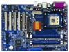
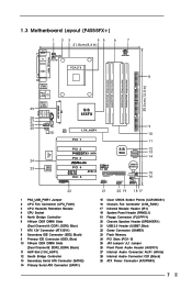
...) 8 Secondary IDE Connector (IDE2, Black) 9 Primary IDE Connector (IDE1, Blue) 10 184-pin DDR DIMM Slots (Dual Channel B: DDR2, DDR4; 1.3 Motherboard Layout (P4S55FX+) 1 23 45 6 7 21.8cm (8.6 in) PS2 Mouse PS2 Keyboard 1 PS2_USB_PWR1 CPU_FAN1 ATX12V1 PARALLEL PORT COM1 PGA478 IDE2 8 DDR1 (64/72 bit, 184...CD1 AUDIO1 1 AUX1 JR1 JL1 Audio CODEC Super I/O 24 23 2MB BIOS ATXPWR1 SiS 655FX LAN 1.5V_AGP1 PHY PCI 1 9 IDE1 10 11 PCI 2 P4S55FX+ SATA PCI 3 PCI 4 AGP 8X DDR400 PCI 5 GAME1 FSB800 USB2.0 5.1 CH ATA133 FLOPPY1 USB67 1 SiS 964 SATA2 SATA1 CMOS Battery SPEAKER1 1 ...
...) 8 Secondary IDE Connector (IDE2, Black) 9 Primary IDE Connector (IDE1, Blue) 10 184-pin DDR DIMM Slots (Dual Channel B: DDR2, DDR4; 1.3 Motherboard Layout (P4S55FX+) 1 23 45 6 7 21.8cm (8.6 in) PS2 Mouse PS2 Keyboard 1 PS2_USB_PWR1 CPU_FAN1 ATX12V1 PARALLEL PORT COM1 PGA478 IDE2 8 DDR1 (64/72 bit, 184...CD1 AUDIO1 1 AUX1 JR1 JL1 Audio CODEC Super I/O 24 23 2MB BIOS ATXPWR1 SiS 655FX LAN 1.5V_AGP1 PHY PCI 1 9 IDE1 10 11 PCI 2 P4S55FX+ SATA PCI 3 PCI 4 AGP 8X DDR400 PCI 5 GAME1 FSB800 USB2.0 5.1 CH ATA133 FLOPPY1 USB67 1 SiS 964 SATA2 SATA1 CMOS Battery SPEAKER1 1 ...
User Manual
Page 8
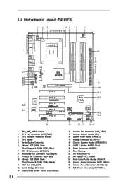
... Audio Header (AUDIO1) 25 Internal Audio Connector: AUX1 (White) 26 Internal Audio Connector: CD1 (Black) 27 ATX Power Connector (ATXPWR1) 1.4 Motherboard Layout (P4S55FX) 1 23 45 6 7 21.8cm (8.6 in) PS2 Mouse PS2 Keyboard 1 PS2_USB_PWR1 CPU_FAN1 ATX12V1 PARALLEL PORT COM1 PGA478 IDE2 8 DDR1 (64...CD1 AUDIO1 1 AUX1 JR1 JL1 Audio CODEC Super I/O 22 21 2MB BIOS ATXPWR1 SiS 655FX LAN 1.5V_AGP1 PHY PCI 1 9 IDE1 10 11 PCI 2 P4S55FX PCI 3 PCI 4 AGP 8X DDR400 PCI 5 GAME1 ATA133 FSB800 USB2.0 5.1 CH FLOPPY1 USB67 1 SiS 964L CMOS Battery SPEAKER1 1 CLRCMOS1 CHA_FAN1 IR1 1...
... Audio Header (AUDIO1) 25 Internal Audio Connector: AUX1 (White) 26 Internal Audio Connector: CD1 (Black) 27 ATX Power Connector (ATXPWR1) 1.4 Motherboard Layout (P4S55FX) 1 23 45 6 7 21.8cm (8.6 in) PS2 Mouse PS2 Keyboard 1 PS2_USB_PWR1 CPU_FAN1 ATX12V1 PARALLEL PORT COM1 PGA478 IDE2 8 DDR1 (64...CD1 AUDIO1 1 AUX1 JR1 JL1 Audio CODEC Super I/O 22 21 2MB BIOS ATXPWR1 SiS 655FX LAN 1.5V_AGP1 PHY PCI 1 9 IDE1 10 11 PCI 2 P4S55FX PCI 3 PCI 4 AGP 8X DDR400 PCI 5 GAME1 ATA133 FSB800 USB2.0 5.1 CH FLOPPY1 USB67 1 SiS 964L CMOS Battery SPEAKER1 1 CLRCMOS1 CHA_FAN1 IR1 1...
User Manual
Page 10
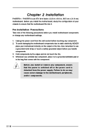
... the carpet or the like. Before you install or remove any component. 2. Pre-installation Precautions Take note of your motherboard directly on a grounded antistatic pad or in , 30.5 cm x 21.8 cm) motherboard. Chapter 2 Installation P4S55FX+ / P4S55FX is detached from the wall socket before you handle components. 3. Failure to do not touch the ICs. 4. To...
... the carpet or the like. Before you install or remove any component. 2. Pre-installation Precautions Take note of your motherboard directly on a grounded antistatic pad or in , 30.5 cm x 21.8 cm) motherboard. Chapter 2 Installation P4S55FX+ / P4S55FX is detached from the wall socket before you handle components. 3. Failure to do not touch the ICs. 4. To...
User Manual
Page 11
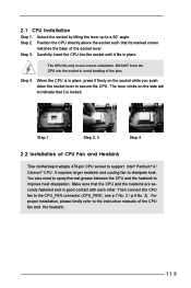
... in place. Step 1 Step 2, 3 Step 4 2.2 Installation of the socket lever. Make sure that its marked corner matches the base of CPU Fan and Heatsink This motherboard adopts 478-pin CPU socket to dissipate heat. It requires larger heatsink and cooling fan to support Intel® Pentium® 4 / Celeron® CPU. Position...
... in place. Step 1 Step 2, 3 Step 4 2.2 Installation of the socket lever. Make sure that its marked corner matches the base of CPU Fan and Heatsink This motherboard adopts 478-pin CPU socket to dissipate heat. It requires larger heatsink and cooling fan to support Intel® Pentium® 4 / Celeron® CPU. Position...

User Manual
Page 12
... to install them either in the set of blue slots (DDR1 and DDR3), or in the set of the same color. This motherboard also allows you have to install four DDR DIMMs for dual channel configuration. Please refer to activate the Dual Channel Memory Technology. 3....(Black Slot) 1. For dual channel configuration, you want to install two memory modules, for example, installing a pair of Memory Modules (DIMM) P4S55FX+ / P4S55FX motherboard provides four 184-pin DDR (Double Data Rate) DIMM slots, and supports Dual Channel Memory Technology. 2.3 Installation of memory modules in DDR1 and DDR2...
... to install them either in the set of blue slots (DDR1 and DDR3), or in the set of the same color. This motherboard also allows you have to install four DDR DIMMs for dual channel configuration. Please refer to activate the Dual Channel Memory Technology. 3....(Black Slot) 1. For dual channel configuration, you want to install two memory modules, for example, installing a pair of Memory Modules (DIMM) P4S55FX+ / P4S55FX motherboard provides four 184-pin DDR (Double Data Rate) DIMM slots, and supports Dual Channel Memory Technology. 2.3 Installation of memory modules in DDR1 and DDR2...
User Manual
Page 13
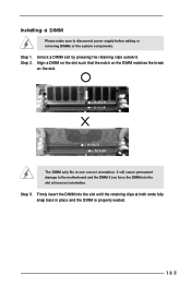
Firmly insert the DIMM into the slot at both ends fully snap back in one correct orientation. Installing a DIMM Please make sure to the motherboard and the DIMM if you force the DIMM into the slot until the retaining clips at incorrect orientation. Unlock a DIMM slot by pressing the retaining ...
Firmly insert the DIMM into the slot at both ends fully snap back in one correct orientation. Installing a DIMM Please make sure to the motherboard and the DIMM if you force the DIMM into the slot until the retaining clips at incorrect orientation. Unlock a DIMM slot by pressing the retaining ...

User Manual
Page 14
...motherboard! Remove the bracket facing the slot that have the 32-bit PCI interface. Step 5. PCI slots: PCI slots are 5 PCI slots and 1 AGP slot on the slot. It may cause permanent damage! Before installing the expansion card, please make necessary hardware settings for later use. Step 4. Step 6. Step 3. The ASRock... of the expansion card and make sure that the power supply is switched off or the power cord is completely seated on P4S55FX+ / P4S55FX motherboard. Remove the system unit cover (if your AGP card, please check with the slot and press firmly until the card is...
...motherboard! Remove the bracket facing the slot that have the 32-bit PCI interface. Step 5. PCI slots: PCI slots are 5 PCI slots and 1 AGP slot on the slot. It may cause permanent damage! Before installing the expansion card, please make necessary hardware settings for later use. Step 4. Step 6. Step 3. The ASRock... of the expansion card and make sure that the power supply is switched off or the power cord is completely seated on P4S55FX+ / P4S55FX motherboard. Remove the system unit cover (if your AGP card, please check with the slot and press firmly until the card is...

User Manual
Page 16
...pin IDE1, see p.7 No. 9 / p.8, No. 9) (39-pin IDE2, see p.7 No. 14) SATA2 SATA1 Serial ATA (SATA) connectors are NOT jumpers. Serial ATA Connectors (Only on P4S55FX+ motherboard) (SATA2: see p.7 No. 13) (SATA1: see p.7 No. 8 / p.8, No. 8) PIN1 IDE1 PIN1 IDE2 connect the blue end to the... be connected to the IDE devices 80-conductor ATA 66/100/133 cable Note: If you use only one IDE device on P4S55FX+ motherboard. Serial ATA (SATA) Data Cable (Only for P4S55FX+ motherboard) 16 Either end of your hard disk drive to the primary IDE connector (IDE1, blue) and CD-ROM to 1.5 Gb/s ...
...pin IDE1, see p.7 No. 9 / p.8, No. 9) (39-pin IDE2, see p.7 No. 14) SATA2 SATA1 Serial ATA (SATA) connectors are NOT jumpers. Serial ATA Connectors (Only on P4S55FX+ motherboard) (SATA2: see p.7 No. 13) (SATA1: see p.7 No. 8 / p.8, No. 8) PIN1 IDE1 PIN1 IDE2 connect the blue end to the... be connected to the IDE devices 80-conductor ATA 66/100/133 cable Note: If you use only one IDE device on P4S55FX+ motherboard. Serial ATA (SATA) Data Cable (Only for P4S55FX+ motherboard) 16 Either end of your hard disk drive to the primary IDE connector (IDE1, blue) and CD-ROM to 1.5 Gb/s ...
User Manual
Page 17
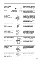
...connectors allow you 6 default USB 2.0 ports on each drive. Please connect the chassis speaker to this USB 2.0 header is an interface for P4S55FX+ motherboard) (Optional) connect to the SATA HDD power connector connect to the power supply Please connect the black end of audio devices. O U ... p.8 No. 16) Chassis Speaker Header (4-pin SPEAKER 1) (see p.7 No. 21 / p.8 No. 19) USB_PWR P-7 P+7 GND DUMMY 1 GND P+6 P-6 USB_PWR ASRock I/O PlusTM provides you to the power connector of the power supply. If the rear USB ports are not sufficient, this header. 17 L GND A U D - Then...
...connectors allow you 6 default USB 2.0 ports on each drive. Please connect the chassis speaker to this USB 2.0 header is an interface for P4S55FX+ motherboard) (Optional) connect to the SATA HDD power connector connect to the power supply Please connect the black end of audio devices. O U ... p.8 No. 16) Chassis Speaker Header (4-pin SPEAKER 1) (see p.7 No. 21 / p.8 No. 19) USB_PWR P-7 P+7 GND DUMMY 1 GND P+6 P-6 USB_PWR ASRock I/O PlusTM provides you to the power connector of the power supply. If the rear USB ports are not sufficient, this header. 17 L GND A U D - Then...

User Manual
Page 19
... as RAID1 then it is called "Hot Plug" for the action to the SATA hard disk. 2.8 Hot Plug and Hot Swap Functions for SATA HDDs P4S55FX+ motherboard supports Hot Plug function for HDDs. However, please note that it is called "Hot Swap" for the action to install the SATA hard disks. This... insert and remove the SATA HDDs while the system is still power-on our website www.asrock.com NOTE What is Hot Swap Function? If you want to use RAID function, please continue to the motherboard's secondary SATA connector (SATA2). What is Hot Plug Function? If SATA HDDs are NOT set for...
... as RAID1 then it is called "Hot Plug" for the action to the SATA hard disk. 2.8 Hot Plug and Hot Swap Functions for SATA HDDs P4S55FX+ motherboard supports Hot Plug function for HDDs. However, please note that it is called "Hot Swap" for the action to install the SATA hard disks. This... insert and remove the SATA HDDs while the system is still power-on our website www.asrock.com NOTE What is Hot Swap Function? If you want to use RAID function, please continue to the motherboard's secondary SATA connector (SATA2). What is Hot Plug Function? If SATA HDDs are NOT set for...
User Manual
Page 21
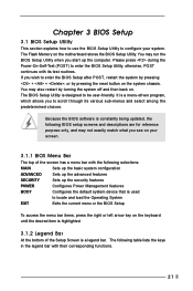
... the menu bar items, press the right or left arrow key on your system. You may also restart by pressing the reset button on the motherboard stores the BIOS Setup Utility. The Flash Memory on the system chassis. The following selections: MAIN Sets up the basic system configuration ADVANCED Sets up...
... the menu bar items, press the right or left arrow key on your system. You may also restart by pressing the reset button on the motherboard stores the BIOS Setup Utility. The Flash Memory on the system chassis. The following selections: MAIN Sets up the basic system configuration ADVANCED Sets up...
User Manual
Page 25
... how to install your OS documentation for more about ASRock, welcome to visit ASRock's website at http://www.asrock.com; or you may contact your dealer for general reference only. Refer to know more information. 4.2 Support CD Information The Support CD that came with the motherboard contains necessary drivers and useful utilities that the...
... how to install your OS documentation for more about ASRock, welcome to visit ASRock's website at http://www.asrock.com; or you may contact your dealer for general reference only. Refer to know more information. 4.2 Support CD Information The Support CD that came with the motherboard contains necessary drivers and useful utilities that the...

User Manual
Page 26
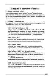
...Hyper-Threading technology and an operating system that times the frontside bus frequency will equal the core speed of the installed motherboard. You may also select other value as Microsoft® Windows® XP. This option will detect the memory ...module(s) inserted and assigns appropriate frequency automatically. If the installed CPU is selected, the motherboard will be available. Advanced BIOS Setup Menu Main Advanced AMIBIOS SETUP UTILITY - Chipset Configuration Resource Configuration Peripheral Configuration System Hardware ...
...Hyper-Threading technology and an operating system that times the frontside bus frequency will equal the core speed of the installed motherboard. You may also select other value as Microsoft® Windows® XP. This option will detect the memory ...module(s) inserted and assigns appropriate frequency automatically. If the installed CPU is selected, the motherboard will be available. Advanced BIOS Setup Menu Main Advanced AMIBIOS SETUP UTILITY - Chipset Configuration Resource Configuration Peripheral Configuration System Hardware ...

User Manual
Page 30
...AC'97 Audio: Select [Disabled], [Auto] or [Enabled] for Game Port or disable Game Port. OnBoard Midi Port: Select address for P4S55FX+ motherboard. OnBoard Parallel Port: Select Parallel Port address or disable Parallel Port. Configuration options: [Auto], [Disabled], [378], [278]. Midi IRQ ...Select: Use this to monitor the parameters for CPU temperature, Motherboard temperature, CPU fan speed, and critical voltage. OnBoard LAN: This allows you to enable or disable the onboard SATA controller. System Hardware...
...AC'97 Audio: Select [Disabled], [Auto] or [Enabled] for Game Port or disable Game Port. OnBoard Midi Port: Select address for P4S55FX+ motherboard. OnBoard Parallel Port: Select Parallel Port address or disable Parallel Port. Configuration options: [Auto], [Disabled], [378], [278]. Midi IRQ ...Select: Use this to monitor the parameters for CPU temperature, Motherboard temperature, CPU fan speed, and critical voltage. OnBoard LAN: This allows you to enable or disable the onboard SATA controller. System Hardware...

