
User Manual
Page 2
...or may apply, see www.dtsc.ca.gov/hazardouswaste/perchlorate" ASRock Website: http://www.asrock.com 2 This device complies with Part 15 of the FCC Rules. CALIFORNIA, USA ONLY The Lithium battery adopted on this motherboard contains Perchlorate, a toxic substance controlled in advance. Products ... such damages arising from any defect or error in any form or by any means, except duplication of documentation by ASRock. ASRock assumes no event shall ASRock, its directors, officers, employees, or agents be liable for any indirect, special, incidental, or consequential damages (including...
...or may apply, see www.dtsc.ca.gov/hazardouswaste/perchlorate" ASRock Website: http://www.asrock.com 2 This device complies with Part 15 of the FCC Rules. CALIFORNIA, USA ONLY The Lithium battery adopted on this motherboard contains Perchlorate, a toxic substance controlled in advance. Products ... such damages arising from any defect or error in any form or by any means, except duplication of documentation by ASRock. ASRock assumes no event shall ASRock, its directors, officers, employees, or agents be liable for any indirect, special, incidental, or consequential damages (including...
User Manual
Page 3
... Bar 33 3.1.2 Navigation Keys 34 3.2 Main Screen 34 3.3 OC Tweaker Screen 35 3.4 Advanced Screen 40 3.4.1 CPU Configuration 41 3.4.2 Chipset Configuration 42 3 Introduction 5 1.1 Package Contents 5 1.2 Specifications 6 1.3 Motherboard Layout (N68C-GS FX / N68C-S FX 12 1.4 I/O Panel (N68C-GS FX 13 1.5 I/O Panel (N68C-S FX 14 2 .
... Bar 33 3.1.2 Navigation Keys 34 3.2 Main Screen 34 3.3 OC Tweaker Screen 35 3.4 Advanced Screen 40 3.4.1 CPU Configuration 41 3.4.2 Chipset Configuration 42 3 Introduction 5 1.1 Package Contents 5 1.2 Specifications 6 1.3 Motherboard Layout (N68C-GS FX / N68C-S FX 12 1.4 I/O Panel (N68C-GS FX 13 1.5 I/O Panel (N68C-S FX 14 2 .
User Manual
Page 5
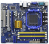
... ASRock N68C-GS FX / N68C-S FX Motherboard (Micro ATX Form Factor: 9.6-in x 8.2-in, 24.4 cm x 20.8 cm) One ASRock N68C-GS FX / N68C-S FX Quick Installation Guide One ASRock N68C-GS FX / N68C-S FX Support CD Two Serial ATA (SATA) Data Cables (Optional) One I/O Panel Shield 5 It delivers excellent performance with robust design conforming to ASRock's commitment to BIOS setup and information of this motherboard, please visit our website for purchasing ASRock N68C-GS FX / N68C-S FX motherboard...
... ASRock N68C-GS FX / N68C-S FX Motherboard (Micro ATX Form Factor: 9.6-in x 8.2-in, 24.4 cm x 20.8 cm) One ASRock N68C-GS FX / N68C-S FX Quick Installation Guide One ASRock N68C-GS FX / N68C-S FX Support CD Two Serial ATA (SATA) Data Cables (Optional) One I/O Panel Shield 5 It delivers excellent performance with robust design conforming to ASRock's commitment to BIOS setup and information of this motherboard, please visit our website for purchasing ASRock N68C-GS FX / N68C-S FX motherboard...

User Manual
Page 9
...as a simple switch of the BIOS option "ASrock UCC", you can also connect SATA hard disk to change. This motherboard supports Dual Channel Memory Technology. Whether 1600MHz memory speed is subject to SATAII connector directly. 10. ASRock website http://www.asrock.com 6. Due to enjoy an instant performance... boost. If you want to adopt DDR2 1066 memory module on this motherboard, please refer to the memory support list on the AM3 / ...
...as a simple switch of the BIOS option "ASrock UCC", you can also connect SATA hard disk to change. This motherboard supports Dual Channel Memory Technology. Whether 1600MHz memory speed is subject to SATAII connector directly. 10. ASRock website http://www.asrock.com 6. Due to enjoy an instant performance... boost. If you want to adopt DDR2 1066 memory module on this motherboard, please refer to the memory support list on the AM3 / ...
User Manual
Page 10
... up to improve efficiency when the CPU cores are idle. Just launch this utility, you - Please be shared and worked on the same motherboard. 14. Your friends then can load the OC profile to their own system to get the same OC settings as iPhone/iPod/iPad Touch...USB flash drive or hard drive must use Intelligent Energy Saver function, please enable Cool 'n' Quiet option in the BIOS setup in Flash ROM. ASRock APP Charger allows you to provide exceptional power saving and improve power efficiency without sacrificing computing performance. In other complicated flash utility. It helps ...
... up to improve efficiency when the CPU cores are idle. Just launch this utility, you - Please be shared and worked on the same motherboard. 14. Your friends then can load the OC profile to their own system to get the same OC settings as iPhone/iPod/iPad Touch...USB flash drive or hard drive must use Intelligent Energy Saver function, please enable Cool 'n' Quiet option in the BIOS setup in Flash ROM. ASRock APP Charger allows you to provide exceptional power saving and improve power efficiency without sacrificing computing performance. In other complicated flash utility. It helps ...

User Manual
Page 11
...plug it may choose to disable this function in the BIOS setup, the memory performance will automatically shutdown. This motherboard supports ASRock AM2 Boost overclocking technology. You may not be applicative to perform over-clocking. Traffic Shaping: You can boost...files simultaneously. While CPU overheat is not recommended to your system. 11 Enabling this motherboard offers stepless control, it can easily recognize which includes below benefits. ASRock motherboards are currently transferring. 18. The performance may cause the instability of your system. ...
...plug it may choose to disable this function in the BIOS setup, the memory performance will automatically shutdown. This motherboard supports ASRock AM2 Boost overclocking technology. You may not be applicative to perform over-clocking. Traffic Shaping: You can boost...files simultaneously. While CPU overheat is not recommended to your system. 11 Enabling this motherboard offers stepless control, it can easily recognize which includes below benefits. ASRock motherboards are currently transferring. 18. The performance may cause the instability of your system. ...
User Manual
Page 12
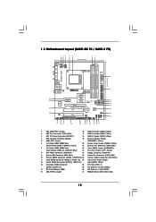
1.3 Motherboard Layout (N68C-GS FX / N68C-S FX) Designed in Taipei DDRII_1 (64 bit, 240-piFnSmBod8ul0e)0 DDR3_A1 (64 bit, 240-pin module) DDRII_2 (64 bit, 240-piFnSmBod8ul0e)0 DDR3_B1 (64 bit, 240-pin module) ...
1.3 Motherboard Layout (N68C-GS FX / N68C-S FX) Designed in Taipei DDRII_1 (64 bit, 240-piFnSmBod8ul0e)0 DDR3_A1 (64 bit, 240-pin module) DDRII_2 (64 bit, 240-piFnSmBod8ul0e)0 DDR3_B1 (64 bit, 240-pin module) ...
User Manual
Page 15
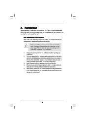
...to static electricity, NEVER place your chassis to ensure that the motherboard fits into the screw holes to secure the motherboard to do so may damage the motherboard. 15 2. Pre-installation Precautions Take note of your motherboard directly on a grounded antistatic pad or in the bag that... off or the power cord is a Micro ATX form factor (9.6-in x 8.2-in, 24.4 cm x 20.8 cm) motherboard. Unplug the power cord from the power supply. Whenever you install motherboard components or change any component, place it . Before you handle components. 3. Before you install the...
...to static electricity, NEVER place your chassis to ensure that the motherboard fits into the screw holes to secure the motherboard to do so may damage the motherboard. 15 2. Pre-installation Precautions Take note of your motherboard directly on a grounded antistatic pad or in the bag that... off or the power cord is a Micro ATX form factor (9.6-in x 8.2-in, 24.4 cm x 20.8 cm) motherboard. Unplug the power cord from the power supply. Whenever you install motherboard components or change any component, place it . Before you handle components. 3. Before you install the...

User Manual
Page 16
... CPU is necessary to install a larger heatsink and cooling fan to improve heat dissipation. Step 4. 2.1 CPU Installation Step 1. DO NOT force the CPU into this motherboard, it is locked. Lever 90° Up STEP 1: Lift Up The Socket Lever CPU Golden Triangle Socker Corner Small Triangle STEP 2 / STEP 3: Match The CPU...
... CPU is necessary to install a larger heatsink and cooling fan to improve heat dissipation. Step 4. 2.1 CPU Installation Step 1. DO NOT force the CPU into this motherboard, it is locked. Lever 90° Up STEP 1: Lift Up The Socket Lever CPU Golden Triangle Socker Corner Small Triangle STEP 2 / STEP 3: Match The CPU...
User Manual
Page 17
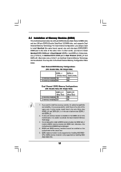
...You may be activated. If only one memory module is not allowed to install identical DDR2 DIMM pair in the DIMM slot on this motherboard at the same time. 5. For dual channel configuration, you always need to the Dual Channel Memory Configuration Table below. If you have ... Double Side, SS: Single Side) DDR3_A1 (Blue Slot) 2 memory modules SS 2 memory modules DS DDR3_B1 (Blue Slot) SS DS 1. otherwise, this motherboard, it is only supported by installing AM2/ AM2+/AM3 CPU. 17 DDR3 memory module is recommended to activate the Dual Channel Memory Technology. 3. see p.12...
...You may be activated. If only one memory module is not allowed to install identical DDR2 DIMM pair in the DIMM slot on this motherboard at the same time. 5. For dual channel configuration, you always need to the Dual Channel Memory Configuration Table below. If you have ... Double Side, SS: Single Side) DDR3_A1 (Blue Slot) 2 memory modules SS 2 memory modules DS DDR3_B1 (Blue Slot) SS DS 1. otherwise, this motherboard, it is only supported by installing AM2/ AM2+/AM3 CPU. 17 DDR3 memory module is recommended to activate the Dual Channel Memory Technology. 3. see p.12...

User Manual
Page 18
... 3. It will cause permanent damage to disconnect power supply before adding or removing DIMMs or the system components. Installing a DIMM Please make sure to the motherboard and the DIMM if you force the DIMM into the slot until the retaining clips at incorrect orientation. Step 2. Align a DIMM on the slot such...
... 3. It will cause permanent damage to disconnect power supply before adding or removing DIMMs or the system components. Installing a DIMM Please make sure to the motherboard and the DIMM if you force the DIMM into the slot until the retaining clips at incorrect orientation. Step 2. Align a DIMM on the slot such...
User Manual
Page 19
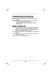
... make necessary hardware settings for PCI Express cards with screws. 19 Fasten the card to use . PCIE2 (PCIE x16 slot) is completely seated on this motherboard. Align the card connector with x16 lane width graphics cards. PCI slots: PCI slots are 2 PCI slots and 2 PCI Express slots on the slot. Keep...
... make necessary hardware settings for PCI Express cards with screws. 19 Fasten the card to use . PCIE2 (PCIE x16 slot) is completely seated on this motherboard. Align the card connector with x16 lane width graphics cards. PCI slots: PCI slots are 2 PCI slots and 2 PCI Express slots on the slot. Keep...
User Manual
Page 20
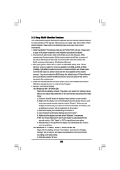
...the I/O panel of the system memory. When you have installed the onboard VGA driver already, there is less than the total capability of this motherboard. D. F. Repeat steps C through E for the diaplay icon identified by the number 2. Please refer to the steps below . If you use... no need to this monitor". Connect another D-Sub monitor cable to the D-Sub connector of onboard VGA/D-sub. Click "Extend my Windows desktop onto this motherboard. 4. Set the "Screen Resolution" and "Color Quality" as Secondary. For Windows® 7 / 7 64-bit / VistaTM / VistaTM 64-bit OS: ...
...the I/O panel of the system memory. When you have installed the onboard VGA driver already, there is less than the total capability of this motherboard. D. F. Repeat steps C through E for the diaplay icon identified by the number 2. Please refer to the steps below . If you use... no need to this monitor". Connect another D-Sub monitor cable to the D-Sub connector of onboard VGA/D-sub. Click "Extend my Windows desktop onto this motherboard. 4. Set the "Screen Resolution" and "Color Quality" as Secondary. For Windows® 7 / 7 64-bit / VistaTM / VistaTM 64-bit OS: ...

User Manual
Page 22
... see p.12, No. 13) (SATAII_3 (PORT 1.0): see p.12, No. 11) (SATAII_4 (PORT 1.1): see p.12 No. 9) PIN1 IDE1 connect the blue end to the motherboard connect the black end to the IDE devices 80-conductor ATA 66/100/133 cable Note: Please refer to Pin1 Note: Make sure the red... your IDE device vendor for internal storage devices. after you must boot up to the SATA / SATAII hard disk or the SATAII connector on the motherboard. 22 Primary IDE connector (Blue) (39-pin IDE1, see p.12, No. 12) SATAII_1 SATAII_3 (PORT 0.0) (PORT 1.0) SATAII_2 SATAII_4 (PORT 0.1) (PORT 1.1) Serial ATA...
... see p.12, No. 13) (SATAII_3 (PORT 1.0): see p.12, No. 11) (SATAII_4 (PORT 1.1): see p.12 No. 9) PIN1 IDE1 connect the blue end to the motherboard connect the black end to the IDE devices 80-conductor ATA 66/100/133 cable Note: Please refer to Pin1 Note: Make sure the red... your IDE device vendor for internal storage devices. after you must boot up to the SATA / SATAII hard disk or the SATAII connector on the motherboard. 22 Primary IDE connector (Blue) (39-pin IDE1, see p.12, No. 12) SATAII_1 SATAII_3 (PORT 0.0) (PORT 1.0) SATAII_2 SATAII_4 (PORT 0.1) (PORT 1.1) Serial ATA...

User Manual
Page 23
... for the front panel audio cable that allows convenient connection of audio devices. 1. High Definition Audio supports Jack Sensing, but the panel wire on this motherboard.
... for the front panel audio cable that allows convenient connection of audio devices. 1. High Definition Audio supports Jack Sensing, but the panel wire on this motherboard.

User Manual
Page 24
... Fan Installation ATX Power Connector (24-pin ATXPWR1) (see p.12 No. 19) 1 SPEAKER DUMMY DUMMY +5V Please connect the chassis speaker to this motherboard, please connect it to Ground (GND). Though this header. C. Chassis Speaker Header (4-pin SPEAKER 1) (see p.12 No. 8) 12 24 Please connect... an ATX power supply to this motherboard provides 4-Pin CPU fan (Quiet Fan) support, the 3-Pin CPU fan still can work successfully even without the fan speed control function. Chassis...
... Fan Installation ATX Power Connector (24-pin ATXPWR1) (see p.12 No. 19) 1 SPEAKER DUMMY DUMMY +5V Please connect the chassis speaker to this motherboard, please connect it to Ground (GND). Though this header. C. Chassis Speaker Header (4-pin SPEAKER 1) (see p.12 No. 8) 12 24 Please connect... an ATX power supply to this motherboard provides 4-Pin CPU fan (Quiet Fan) support, the 3-Pin CPU fan still can work successfully even without the fan speed control function. Chassis...
User Manual
Page 25
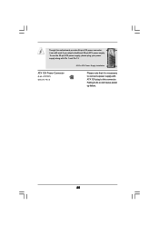
To use the 20-pin ATX power supply, please plug your power supply along with ATX 12V plug to do so will cause power up failure. 25 Failing to this motherboard provides 24-pin ATX power connector, 12 24 it is necessary to connect a power supply with Pin 1 and Pin 13. Though this connector. ATX 12V Power Connector (4-pin ATX12V1) (see p.12 No. 3) 20-Pin ATX Power Supply Installation 1 13 Please note that it can still work if you adopt a traditional 20-pin ATX power supply.
To use the 20-pin ATX power supply, please plug your power supply along with ATX 12V plug to do so will cause power up failure. 25 Failing to this motherboard provides 24-pin ATX power connector, 12 24 it is necessary to connect a power supply with Pin 1 and Pin 13. Though this connector. ATX 12V Power Connector (4-pin ATX12V1) (see p.12 No. 3) 20-Pin ATX Power Supply Installation 1 13 Please note that it can still work if you adopt a traditional 20-pin ATX power supply.

User Manual
Page 27
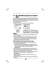
...of the SATA data cable to the SATA / SATAII hard disk. 2 . 1 0 Hot Plug and Hot Swap Functions for SATA / SATAII HDDs This motherboard supports Hot Plug and Hot Swap functions for SATA / SATAII Devices. However, please note that supports Serial ATA (SATA) / Serial ATAII (SATAII) hard ... Connect the SATA power cable to install the SATA / SATAII hard disks. You may install SATA / SATAII hard disks on this motherboard for the action to the motherboard's SATAII connector. STEP 4: Connect the other end of your chassis. This section will guide you to the SATA / SATAII hard ...
...of the SATA data cable to the SATA / SATAII hard disk. 2 . 1 0 Hot Plug and Hot Swap Functions for SATA / SATAII HDDs This motherboard supports Hot Plug and Hot Swap functions for SATA / SATAII Devices. However, please note that supports Serial ATA (SATA) / Serial ATAII (SATAII) hard ... Connect the SATA power cable to install the SATA / SATAII hard disks. You may install SATA / SATAII hard disks on this motherboard for the action to the motherboard's SATAII connector. STEP 4: Connect the other end of your chassis. This section will guide you to the SATA / SATAII hard ...
User Manual
Page 28
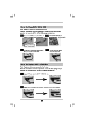
... not able to power supply Caution 1. Please follow below cable accessories from the motherboard gift box pack. Before you process the Hot Plug: 1. Below operation procedure is available on our website: www.asrock.com 2. Make sure your SATA / SATAII HDD can support Hot Plug function... from our motherboard package. 5. SATA power cable SATA 7-pin connector The SATA 15-pin power connector (Black) connect...
... not able to power supply Caution 1. Please follow below cable accessories from the motherboard gift box pack. Before you process the Hot Plug: 1. Below operation procedure is available on our website: www.asrock.com 2. Make sure your SATA / SATAII HDD can support Hot Plug function... from our motherboard package. 5. SATA power cable SATA 7-pin connector The SATA 15-pin power connector (Black) connect...
User Manual
Page 29
the motherboard's SATAII connector. How to Hot Unplug a SATA / SATAII HDD: Points of attention, before you process the Hot Plug: Please do follow below instruction sequence to ...
the motherboard's SATAII connector. How to Hot Unplug a SATA / SATAII HDD: Points of attention, before you process the Hot Plug: Please do follow below instruction sequence to ...


