
RAID Installation Guide
Page 9
One method is "Auto Setup", and another is "Select Disk Drives". Just highlight the target drives that you want to use and press to the creation steps menu. 9 When all drives have been selected, press to go back to select them respectively. Select "Select Disk Drives" to select the disk drives and create array automatically. Select "Auto Setup" to allow BIOS to let user select the array drives manually. 3. When using Select Disk Drives method, the channel column will be activated. There are two methods to create a disk array.
One method is "Auto Setup", and another is "Select Disk Drives". Just highlight the target drives that you want to use and press to the creation steps menu. 9 When all drives have been selected, press to go back to select them respectively. Select "Select Disk Drives" to select the disk drives and create array automatically. Select "Auto Setup" to allow BIOS to let user select the array drives manually. 3. When using Select Disk Drives method, the channel column will be activated. There are two methods to create a disk array.

User Manual
Page 1
K8Upgrade-VM800 User Manual Version 1.0 Published April 2005 Copyright©2005 ASRock INC. All rights reserved. 1
K8Upgrade-VM800 User Manual Version 1.0 Published April 2005 Copyright©2005 ASRock INC. All rights reserved. 1

User Manual
Page 2
...informational use only and subject to change without written consent of ASRock Inc. With respect to the contents of this manual. ASRock Website: http://www.asrock.com 2 This device complies with Part 15 of the FCC Rules. ASRock assumes no event shall ASRock, its directors, officers, employees, or agents be constructed .... Copyright Notice: No part of this device must accept any interference received, including interference that may appear in this manual, ASRock does not provide warranty of any kind, either expressed or implied, including but not limited to the implied warranties or...
...informational use only and subject to change without written consent of ASRock Inc. With respect to the contents of this manual. ASRock Website: http://www.asrock.com 2 This device complies with Part 15 of the FCC Rules. ASRock assumes no event shall ASRock, its directors, officers, employees, or agents be constructed .... Copyright Notice: No part of this device must accept any interference received, including interference that may appear in this manual, ASRock does not provide warranty of any kind, either expressed or implied, including but not limited to the implied warranties or...

User Manual
Page 5
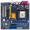
... change without further notice. In case any modifications of this manual occur, the updated version will be available on ASRock website as well. ASRock website http://www.asrock.com 1.1 Package Contents 1 x ASRock K8Upgrade-VM800 Motherboard (Micro ATX Form Factor: 9.0-in x 9.6-in, 22.9 cm x 24.4 cm) 1 x ASRock K8Upgrade-VM800 Quick Installation Guide 1 x ASRock K8Upgrade-VM800 Support CD 1 x Ultra ATA 66/100/133 IDE Ribbon...
... change without further notice. In case any modifications of this manual occur, the updated version will be available on ASRock website as well. ASRock website http://www.asrock.com 1.1 Package Contents 1 x ASRock K8Upgrade-VM800 Motherboard (Micro ATX Form Factor: 9.0-in x 9.6-in, 22.9 cm x 24.4 cm) 1 x ASRock K8Upgrade-VM800 Quick Installation Guide 1 x ASRock K8Upgrade-VM800 Support CD 1 x Ultra ATA 66/100/133 IDE Ribbon...
User Manual
Page 11
... you install the CPU into this motherboard, it fits in good contact with a small triangle. Carefully insert the CPU into the socket to the instruction manuals of the pins. Then connect the CPU fan to a 90o angle. Unlock the socket by lifting the lever up to the CPU FAN connector (CPU_FAN1...
... you install the CPU into this motherboard, it fits in good contact with a small triangle. Carefully insert the CPU into the socket to the instruction manuals of the pins. Then connect the CPU fan to a 90o angle. Unlock the socket by lifting the lever up to the CPU FAN connector (CPU_FAN1...
User Manual
Page 25
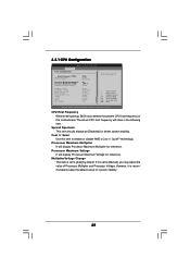
...] for system stability. 25 Processor Maximum Multiplier It will display Processor Maximum Voltage for reference. Cool 'n' Quiet Use this motherboard. If it is set to [Manual], you may adjust the value of this item to enable or disable AMD's Cool 'n' QuietTM technology. The actual CPU host frequency will show in the...
...] for system stability. 25 Processor Maximum Multiplier It will display Processor Maximum Voltage for reference. Cool 'n' Quiet Use this motherboard. If it is set to [Manual], you may adjust the value of this item to enable or disable AMD's Cool 'n' QuietTM technology. The actual CPU host frequency will show in the...

User Manual
Page 26
...Processor Multiplier Processor Voltage Memory Clock Flexibility Option Bank Interleaving Burst Length CAS Latency (CL) TRCD MA Timing [Auto] [200] [Auto] [Disabled] x11 1.550 V [Manual] [x8] [1.500V] [Auto] [Disabled] [Auto] [4 Beats] [Auto] [Auto] [2T] If AUTO, FID/VID will be hidden. You can set this...value of memory accessing. However, for system stability, it will be set to [0.800V]. Bank Interleaving Interleaving allows memory accesses to [Manual]; Memory Clock This item can be spread out over banks on User Selection in Setup. +F1 F9 F10 ESC Select Screen Select Item...
...Processor Multiplier Processor Voltage Memory Clock Flexibility Option Bank Interleaving Burst Length CAS Latency (CL) TRCD MA Timing [Auto] [200] [Auto] [Disabled] x11 1.550 V [Manual] [x8] [1.500V] [Auto] [Disabled] [Auto] [4 Beats] [Auto] [Auto] [2T] If AUTO, FID/VID will be hidden. You can set this...value of memory accessing. However, for system stability, it will be set to [0.800V]. Bank Interleaving Interleaving allows memory accesses to [Manual]; Memory Clock This item can be spread out over banks on User Selection in Setup. +F1 F9 F10 ESC Select Screen Select Item...

Quick Installation Guide
Page 4
... will be found in the user manual presented in Floppy Drive Ribbon Cable 1 x Serial ATA (SATA) Data Cable (Optional) 1 x Serial ATA (SATA) HDD Power Cable (Optional) 1 x ASRock I/O PlusTM Shield 1 x COM Port Bracket 1 x ASRock MR Card (Optional) 4 ASRock K8Upgrade-VM800 Motherboard English It delivers excellent performance with robust design conforming to ASRock's commitment to change without further notice...
... will be found in the user manual presented in Floppy Drive Ribbon Cable 1 x Serial ATA (SATA) Data Cable (Optional) 1 x Serial ATA (SATA) HDD Power Cable (Optional) 1 x ASRock I/O PlusTM Shield 1 x COM Port Bracket 1 x ASRock MR Card (Optional) 4 ASRock K8Upgrade-VM800 Motherboard English It delivers excellent performance with robust design conforming to ASRock's commitment to change without further notice...

Quick Installation Guide
Page 6
Power Management for advanced users' reference, see CAUTION 5) OS: Microsoft® Windows® 98 SE / ME / 2000 / XP compliant CAUTION! 1. English 6 ASRock K8Upgrade-VM800 Motherboard ASRock I/O PlusTM: 1 PS/2 Mouse Port, 1 PS/2 Keyboard Port 1 VGA Port 1 Parallel Port (ECP/EPP Support) 6 Ready-to-Use USB 2.0 Ports 1 RJ-45 Port Audio ... thermal grease between the CPU and the heatsink when you resume the system, please check if the CPU fan on page 39 of "User Manual" in the Support CD to perform over-clocking. Do NOT use a 3.3V AGP card on the AGP slot of the system or damage...
Power Management for advanced users' reference, see CAUTION 5) OS: Microsoft® Windows® 98 SE / ME / 2000 / XP compliant CAUTION! 1. English 6 ASRock K8Upgrade-VM800 Motherboard ASRock I/O PlusTM: 1 PS/2 Mouse Port, 1 PS/2 Keyboard Port 1 VGA Port 1 Parallel Port (ECP/EPP Support) 6 Ready-to-Use USB 2.0 Ports 1 RJ-45 Port Audio ... thermal grease between the CPU and the heatsink when you resume the system, please check if the CPU fan on page 39 of "User Manual" in the Support CD to perform over-clocking. Do NOT use a 3.3V AGP card on the AGP slot of the system or damage...

Quick Installation Guide
Page 7
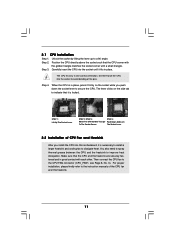
... static electricity, NEVER place your CPU fan and heatsink vendors. Step 3. The lever clicks on the carpet or the like. English 7 ASRock K8Upgrade-VM800 Motherboard When placing screws into the socket to do so may damage the motherboard. 2.1 CPU Installation Step 1. Step 4. Install CPU fan and... to secure the motherboard to the motherboard, peripherals, and/or components. 2. For proper installation, please kindly refer to the instruction manuals of your motherboard directly on the side tab to secure the CPU. Whenever you uninstall any component, place it fits in the ...
... static electricity, NEVER place your CPU fan and heatsink vendors. Step 3. The lever clicks on the carpet or the like. English 7 ASRock K8Upgrade-VM800 Motherboard When placing screws into the socket to do so may damage the motherboard. 2.1 CPU Installation Step 1. Step 4. Install CPU fan and... to secure the motherboard to the motherboard, peripherals, and/or components. 2. For proper installation, please kindly refer to the instruction manuals of your motherboard directly on the side tab to secure the CPU. Whenever you uninstall any component, place it fits in the ...
Quick Installation Guide
Page 19
... select among the predetermined choices. It will enhance motherboard features. For the detailed information about BIOS Setup, please refer to the User Manual (PDF file) contained in the Support CD to scroll through its test routines. If the Main Menu does not appear automatically, locate...Support CD that will display the Main Menu automatically if "AUTORUN" is a menu-driven program, which allows you to display the menus. 19 ASRock K8Upgrade-VM800 Motherboard English EXE" from the "BIN" folder in the Support CD. 4. It is enabled in your CD-ROM drive. BIOS Information The ...
... select among the predetermined choices. It will enhance motherboard features. For the detailed information about BIOS Setup, please refer to the User Manual (PDF file) contained in the Support CD to scroll through its test routines. If the Main Menu does not appear automatically, locate...Support CD that will display the Main Menu automatically if "AUTORUN" is a menu-driven program, which allows you to display the menus. 19 ASRock K8Upgrade-VM800 Motherboard English EXE" from the "BIN" folder in the Support CD. 4. It is enabled in your CD-ROM drive. BIOS Information The ...
