User Manual
Page 3
... Advanced BIOS Setup Menu 24 2. Security Setup Menu 28 3. Contents 1 Introduction 4 1.1 Package Contents 4 1.2 Specifications 5 1.3 Motherboard Layout (K7S41 7 1.4 Motherboard Layout (K7S41GX 8 1.5 ASRock I/OTM (K7S41 / K7S41GX 9 2 Installation 10 Pre-installation Precautions 10 2.1 CPU Installation 11 2.2 Installation of CPU Fan and Heatsink 11 2.3 Installation of Memory...CD Information 23 4.2.1 Running Support CD 23 4.2.2 Drivers Menu 23 4.2.3 Utilities Menu 23 4.2.4 ASRock "PC-DIY Live Demo" Program 23 4.2.5 Contact Information 23 Appendix 24 1. Power Setup Menu 29 4.
... Advanced BIOS Setup Menu 24 2. Security Setup Menu 28 3. Contents 1 Introduction 4 1.1 Package Contents 4 1.2 Specifications 5 1.3 Motherboard Layout (K7S41 7 1.4 Motherboard Layout (K7S41GX 8 1.5 ASRock I/OTM (K7S41 / K7S41GX 9 2 Installation 10 Pre-installation Precautions 10 2.1 CPU Installation 11 2.2 Installation of CPU Fan and Heatsink 11 2.3 Installation of Memory...CD Information 23 4.2.1 Running Support CD 23 4.2.2 Drivers Menu 23 4.2.3 Utilities Menu 23 4.2.4 ASRock "PC-DIY Live Demo" Program 23 4.2.5 Contact Information 23 Appendix 24 1. Power Setup Menu 29 4.

User Manual
Page 4
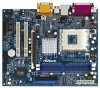
... subject to quality and endurance. In case any modifications of the motherboard and step-bystep installation guide. ASRock website http://www.asrock.com 1.1 Package Contents ASRock K7S41 or K7S41GX Motherboard (Micro ATX Form Factor: 9.6-in x 7.8-in, 24.4 cm x 19.8 cm) ASRock K7S41 / K7S41GX Quick Installation Guide ASRock K7S41 / K7S41GX Support CD One 80-conductor Ultra ATA 66/100/133 IDE...
... subject to quality and endurance. In case any modifications of the motherboard and step-bystep installation guide. ASRock website http://www.asrock.com 1.1 Package Contents ASRock K7S41 or K7S41GX Motherboard (Micro ATX Form Factor: 9.6-in x 7.8-in, 24.4 cm x 19.8 cm) ASRock K7S41 / K7S41GX Quick Installation Guide ASRock K7S41 / K7S41GX Support CD One 80-conductor Ultra ATA 66/100/133 IDE...

User Manual
Page 6
...Microsoft® Windows® 98 SE / ME / 2000 / XP compliant CAUTION! 1. The CPU host frequency of this motherboard! Please check if the CPU fan on the motherboard functions properly before you use a 3.3V AGP card on the AGP slot of the system or damage the CPU. To improve...174; Windows® 98/ME. Frequencies other than the recommended CPU bus frequencies may cause permanent damage! 3. It may cause the instability of this motherboard is determined by the jumper-setting. BIOS: OS: AMI legal BIOS, "Plug and Play" support, ACPI 1.1 compliance wake up events, SMBIOS ...
...Microsoft® Windows® 98 SE / ME / 2000 / XP compliant CAUTION! 1. The CPU host frequency of this motherboard! Please check if the CPU fan on the motherboard functions properly before you use a 3.3V AGP card on the AGP slot of the system or damage the CPU. To improve...174; Windows® 98/ME. Frequencies other than the recommended CPU bus frequencies may cause permanent damage! 3. It may cause the instability of this motherboard is determined by the jumper-setting. BIOS: OS: AMI legal BIOS, "Plug and Play" support, ACPI 1.1 compliance wake up events, SMBIOS ...
User Manual
Page 7
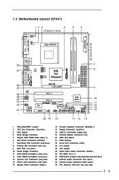
1.3 Motherboard Layout (K7S41) 12 3 4 19.8cm (7.8-in) PS2 Mouse PS2_USB_PWR1 1 PS2 Keyboard CPU_FAN1 5 6 24.4cm (9.6-in) ATXPWR1 PARALLEL PORT VGA1 DDR1 (64/72 bit, 184-pin ...
1.3 Motherboard Layout (K7S41) 12 3 4 19.8cm (7.8-in) PS2 Mouse PS2_USB_PWR1 1 PS2 Keyboard CPU_FAN1 5 6 24.4cm (9.6-in) ATXPWR1 PARALLEL PORT VGA1 DDR1 (64/72 bit, 184-pin ...
User Manual
Page 8
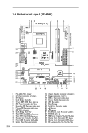
1.4 Motherboard Layout (K7S41GX) 12 3 4 19.8cm (7.8-in) PS2 Mouse PS2_USB_PWR1 1 PS2 Keyboard CPU_FAN1 5 6 24.4cm (9.6-in) ATXPWR1 PARALLEL PORT VGA1 DDR1 (64/72 bit, 184-pin module) DDR2 (... 1 FSB_SEL1 1 FSB_SEL0 SiS 741GX Chipset AGP 8X 1.5V_AGP1 ` ATA133 IDE2 IDE1 AUDIO CODEC AUDIO1 1 JR1 JL1 COM1 1 2MB BIOS PCI 1 Super I/O AMR1 PCI 2 SiS 963L K7S41GX IR1 1 USB45 1 CMOS CLRCMOS1 Battery 5.1CH CLRCMOS2 FLOPPY1 USB 2.0 CHA_FAN1 PWR_LED1 1 PLED PWRBTN SPEAKER1 PANEL 1 1 1 HDLED RST 20 19 18 17 16 15 7 8 9 10 11...
1.4 Motherboard Layout (K7S41GX) 12 3 4 19.8cm (7.8-in) PS2 Mouse PS2_USB_PWR1 1 PS2 Keyboard CPU_FAN1 5 6 24.4cm (9.6-in) ATXPWR1 PARALLEL PORT VGA1 DDR1 (64/72 bit, 184-pin module) DDR2 (... 1 FSB_SEL1 1 FSB_SEL0 SiS 741GX Chipset AGP 8X 1.5V_AGP1 ` ATA133 IDE2 IDE1 AUDIO CODEC AUDIO1 1 JR1 JL1 COM1 1 2MB BIOS PCI 1 Super I/O AMR1 PCI 2 SiS 963L K7S41GX IR1 1 USB45 1 CMOS CLRCMOS1 Battery 5.1CH CLRCMOS2 FLOPPY1 USB 2.0 CHA_FAN1 PWR_LED1 1 PLED PWRBTN SPEAKER1 PANEL 1 1 1 HDLED RST 20 19 18 17 16 15 7 8 9 10 11...

User Manual
Page 10
...or touch a safety grounded object before you handle components. 3. To avoid damaging the motherboard components due to the motherboard, peripherals, and/or components. 10 Chapter 2 Installation K7S41 / K7S41GX is detached from the wall socket before touching any component. 2. Unplug the power cord... from the power supply. Before you install the motherboard, please study the configuration of the following precautions before ...
...or touch a safety grounded object before you handle components. 3. To avoid damaging the motherboard components due to the motherboard, peripherals, and/or components. 10 Chapter 2 Installation K7S41 / K7S41GX is detached from the wall socket before touching any component. 2. Unplug the power cord... from the power supply. Before you install the motherboard, please study the configuration of the following precautions before ...

User Manual
Page 11
... the CPU_FAN connector (CPU_FAN1, see page 7/page 8, No. 2). Step 4. For proper installation, please kindly refer to the instruction manuals of CPU Fan and Heatsink This motherboard adopts 462-pin CPU socket to support AMD Athlon XP / Duron CPU. The lever clicks on the socket while you push down the socket lever...
... the CPU_FAN connector (CPU_FAN1, see page 7/page 8, No. 2). Step 4. For proper installation, please kindly refer to the instruction manuals of CPU Fan and Heatsink This motherboard adopts 462-pin CPU socket to support AMD Athlon XP / Duron CPU. The lever clicks on the socket while you push down the socket lever...

User Manual
Page 12
2.3 Installation of Memory Modules (DIMM) K7S41 / K7S41GX motherboard provides two 184-pin DDR (Double Data Rate) DIMM slots. Step 3. notch break notch break The DIMM only fits in place and the DIMM is .... Align a DIMM on the slot such that the notch on the DIMM matches the break on the slot. Step 1. Step 2. Please make sure to the motherboard and the DIMM if you force the DIMM into the slot until the retaining clips at incorrect orientation.
2.3 Installation of Memory Modules (DIMM) K7S41 / K7S41GX motherboard provides two 184-pin DDR (Double Data Rate) DIMM slots. Step 3. notch break notch break The DIMM only fits in place and the DIMM is .... Align a DIMM on the slot such that the notch on the DIMM matches the break on the slot. Step 1. Step 2. Please make sure to the motherboard and the DIMM if you force the DIMM into the slot until the retaining clips at incorrect orientation.

User Manual
Page 13
...to the chassis with the graphics card vendors. PCI slots: PCI slots are 2 PCI slots, 1 AMR slot, and 1 AGP slot on K7S41 / K7S41GX motherboard. It may cause permanent damage! Before installing the expansion card, please make necessary hardware settings for later use a 3.3V AGP card on the slot.... card, please check with screws. 2.4 Expansion Slots (PCI, AMR, and AGP Slots) There are used to install a graphics card. The ASRock AGP slot has a special design of the expansion card and make sure that you start the installation. Please read the documentation of clasp that can...
...to the chassis with the graphics card vendors. PCI slots: PCI slots are 2 PCI slots, 1 AMR slot, and 1 AGP slot on K7S41 / K7S41GX motherboard. It may cause permanent damage! Before installing the expansion card, please make necessary hardware settings for later use a 3.3V AGP card on the slot.... card, please check with screws. 2.4 Expansion Slots (PCI, AMR, and AGP Slots) There are used to install a graphics card. The ASRock AGP slot has a special design of the expansion card and make sure that you start the installation. Please read the documentation of clasp that can...

User Manual
Page 14
...200MHz 2_3 FSB_SEL2 2_3 FSB_SEL1 2_3 FSB_SEL0 FSB 266MHz FSB_SEL2 FSB_SEL1 FSB_SEL0 2_3 1_2 1_2 FSB 333MHz 1_2 FSB_SEL2 1_2 FSB_SEL1 1_2 FSB_SEL0 FSB 400MHz K7S41GX: FSB_SEL1 FSB_SEL0 1_2 2_3 FSB 200MHz 2_3 FSB_SEL1 2_3 FSB_SEL0 FSB 266MHz 1_2 FSB_SEL1 1_2 FSB_SEL0 FSB 333MHz Note: The setting of the ...CPU front side bus frequency of this motherboard is placed on the pins, the jumper is "SHORT". When the jumper cap is placed on pins, the jumper is "OPEN". If no ...
...200MHz 2_3 FSB_SEL2 2_3 FSB_SEL1 2_3 FSB_SEL0 FSB 266MHz FSB_SEL2 FSB_SEL1 FSB_SEL0 2_3 1_2 1_2 FSB 333MHz 1_2 FSB_SEL2 1_2 FSB_SEL1 1_2 FSB_SEL0 FSB 400MHz K7S41GX: FSB_SEL1 FSB_SEL0 1_2 2_3 FSB 200MHz 2_3 FSB_SEL1 2_3 FSB_SEL0 FSB 266MHz 1_2 FSB_SEL1 1_2 FSB_SEL0 FSB 333MHz Note: The setting of the ...CPU front side bus frequency of this motherboard is placed on the pins, the jumper is "SHORT". When the jumper cap is placed on pins, the jumper is "OPEN". If no ...
User Manual
Page 16
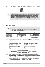
...cause the instability of the system or damage the CPU. 2.6 Connectors Connectors are not provided by ASRock. DO NOT place jumper caps over the connectors will cause permanent damage of the motherboard! Please refer to all multiplier-locked or even some unlocked AMD CPU. Frequencies other than the ... adjustment of multiplier. Connector FDD Connector (33-pin FLOPPY1) (see p.7/p.8 No. 7) PIN1 IDE1 PIN1 IDE2 connect the blue end to the motherboard connect the black end to the IDE devices 80-conductor, ATA 66/100/133 cable Note: If you use only one IDE device on this...
...cause the instability of the system or damage the CPU. 2.6 Connectors Connectors are not provided by ASRock. DO NOT place jumper caps over the connectors will cause permanent damage of the motherboard! Please refer to all multiplier-locked or even some unlocked AMD CPU. Frequencies other than the ... adjustment of multiplier. Connector FDD Connector (33-pin FLOPPY1) (see p.7/p.8 No. 7) PIN1 IDE1 PIN1 IDE2 connect the blue end to the motherboard connect the black end to the IDE devices 80-conductor, ATA 66/100/133 cable Note: If you use only one IDE device on this...

User Manual
Page 19
... configuration ADVANCED Sets up the advanced features SECURITY Sets up the computer. You may also restart the system by pressing the reset button on the motherboard stores the BIOS Setup Utility.
... configuration ADVANCED Sets up the advanced features SECURITY Sets up the computer. You may also restart the system by pressing the reset button on the motherboard stores the BIOS Setup Utility.

User Manual
Page 23
...ASRock presents you a multimedia PC-DIY live demo, which shows you how to install your computer. Install the necessary drivers to display the menus. 4.2.2 Drivers Menu The Drivers Menu shows the available devices drivers if the system detects installed devices. Chapter 4 Software Support 4.1 Install Operating System This motherboard... the Support CD to activate the devices. 4.2.3 Utilities Menu The Utilities Menu shows the applications software that will enhance the motherboard features. 4.2.1 Running The Support CD To begin using the support CD, insert the CD into your CD-ROM drive. ...
...ASRock presents you a multimedia PC-DIY live demo, which shows you how to install your computer. Install the necessary drivers to display the menus. 4.2.2 Drivers Menu The Drivers Menu shows the available devices drivers if the system detects installed devices. Chapter 4 Software Support 4.1 Install Operating System This motherboard... the Support CD to activate the devices. 4.2.3 Utilities Menu The Utilities Menu shows the applications software that will enhance the motherboard features. 4.2.1 Running The Support CD To begin using the support CD, insert the CD into your CD-ROM drive. ...
User Manual
Page 24
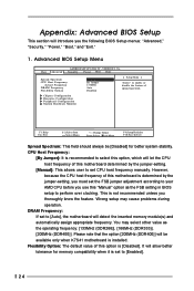
...Change Values Enter:Select Sub-Menu F9:Setup Defaults F10:Save & Exit Spread Spectrum: This field should always be available only when K7S41 motherboard is not recommended unless you the following BIOS Setup menus: "Advanced," "Security," "Power," "Boot," and "Exit." 1. It will...24 Flexibility Option: The default value of spread spectrum. DRAM Frequency: If set the FSB jumper adjustment according to [Auto], the motherboard will detect the inserted memory module(s) and automatically assign appropriate frequency. Please note that the option [200MHz (DDR400)] will be [...
...Change Values Enter:Select Sub-Menu F9:Setup Defaults F10:Save & Exit Spread Spectrum: This field should always be available only when K7S41 motherboard is not recommended unless you the following BIOS Setup menus: "Advanced," "Security," "Power," "Boot," and "Exit." 1. It will...24 Flexibility Option: The default value of spread spectrum. DRAM Frequency: If set the FSB jumper adjustment according to [Auto], the motherboard will detect the inserted memory module(s) and automatically assign appropriate frequency. Please note that the option [200MHz (DDR400)] will be [...

User Manual
Page 27
... Port. OnBoard Game Port: Select address for the onboard AC'97 Audio feature. OnBoard MC'97 Modem: Select [Disabled], [Auto] or [Enabled] for CPU temperature, Motherboard temperature, CPU fan speed, and critical voltage.
... Port. OnBoard Game Port: Select address for the onboard AC'97 Audio feature. OnBoard MC'97 Modem: Select [Disabled], [Auto] or [Enabled] for CPU temperature, Motherboard temperature, CPU fan speed, and critical voltage.

Quick Installation Guide
Page 1
In no responsibility for any defect or error in the guide or product. All rights reserved. 1 ASRock K7S41 / K7S41GX Motherboard English ASRock assumes no event shall ASRock, its directors, officers, employees, or agents be liable for any indirect, special, incidental, or consequential damages (including damages for loss of profits, loss of business, ...
In no responsibility for any defect or error in the guide or product. All rights reserved. 1 ASRock K7S41 / K7S41GX Motherboard English ASRock assumes no event shall ASRock, its directors, officers, employees, or agents be liable for any indirect, special, incidental, or consequential damages (including damages for loss of profits, loss of business, ...

Quick Installation Guide
Page 2
Motherboard Layout (K7S41) English 1 PS2_USB_PWR1 Jumper 2 CPU Fan Connector (CPU_FAN1) 3 CPU Socket 4 North Bridge Controller 5 184-pin DDR DIMM Slots (DDR 1- 2) 6 ATX Power Connector (ATXPWR1) 7 Secondary ... Select Jumpers (FSB_SEL0/FSB_SEL1/FSB_SEL2) 28 Internal Audio Connector: CD1 (Black) 29 Internal Audio Connector: AUX1 (White) 30 FID Jumpers (FID0, FID1, FID2, FID3, FID4) 2 ASRock K7S41 / K7S41GX Motherboard
Motherboard Layout (K7S41) English 1 PS2_USB_PWR1 Jumper 2 CPU Fan Connector (CPU_FAN1) 3 CPU Socket 4 North Bridge Controller 5 184-pin DDR DIMM Slots (DDR 1- 2) 6 ATX Power Connector (ATXPWR1) 7 Secondary ... Select Jumpers (FSB_SEL0/FSB_SEL1/FSB_SEL2) 28 Internal Audio Connector: CD1 (Black) 29 Internal Audio Connector: AUX1 (White) 30 FID Jumpers (FID0, FID1, FID2, FID3, FID4) 2 ASRock K7S41 / K7S41GX Motherboard

Quick Installation Guide
Page 3
Motherboard Layout (K7S41GX) English 1 PS2_USB_PWR1 Jumper 2 CPU Fan Connector (CPU_FAN1) 3 CPU Socket 4 North Bridge Controller 5 184-pin DDR DIMM Slots (DDR 1- 2) 6 ATX Power Connector (ATXPWR1) 7 Secondary IDE Connector (... FSB Select Jumpers (FSB_SEL0/FSB_SEL1) 28 Internal Audio Connector: CD1 (Black) 29 Internal Audio Connector: AUX1 (White) 30 FID Jumpers (FID0, FID1, FID2, FID3, FID4) 3 ASRock K7S41 / K7S41GX Motherboard
Motherboard Layout (K7S41GX) English 1 PS2_USB_PWR1 Jumper 2 CPU Fan Connector (CPU_FAN1) 3 CPU Socket 4 North Bridge Controller 5 184-pin DDR DIMM Slots (DDR 1- 2) 6 ATX Power Connector (ATXPWR1) 7 Secondary IDE Connector (... FSB Select Jumpers (FSB_SEL0/FSB_SEL1) 28 Internal Audio Connector: CD1 (Black) 29 Internal Audio Connector: AUX1 (White) 30 FID Jumpers (FID0, FID1, FID2, FID3, FID4) 3 ASRock K7S41 / K7S41GX Motherboard

Quick Installation Guide
Page 4
ASRock I/OTM (K7S41 / K7S41GX) 1 Parallel Port 2 RJ-45 Port 3 Game Port 4 Microphone (Pink) 5 Line In (Light Blue) 6 Line Out (Lime) 7 USB 2.0 Ports 8 VGA Port 9 PS/2 Keyboard Port (Purple) 10 PS/2 Mouse Port (Green) English 4 ASRock K7S41 / K7S41GX Motherboard
ASRock I/OTM (K7S41 / K7S41GX) 1 Parallel Port 2 RJ-45 Port 3 Game Port 4 Microphone (Pink) 5 Line In (Light Blue) 6 Line Out (Lime) 7 USB 2.0 Ports 8 VGA Port 9 PS/2 Keyboard Port (Purple) 10 PS/2 Mouse Port (Green) English 4 ASRock K7S41 / K7S41GX Motherboard

Quick Installation Guide
Page 5
... a 3.5-in , 24.4 cm x 19.8 cm) ASRock K7S41 / K7S41GX Quick Installation Guide ASRock K7S41 / K7S41GX Support CD One 80-conductor Ultra ATA 66/100/133 IDE Ribbon Cable One Ribbon Cable for purchasing ASRock K7S41 / K7S41GX motherboard, a reliable motherboard produced under ASRock's consistently stringent quality control. ASRock website http://www.asrock.com 1.1 Package Contents ASRock K7S41 or K7S41GX Motherboard (Micro ATX Form Factor: 9.6-in x 7.8-in...
... a 3.5-in , 24.4 cm x 19.8 cm) ASRock K7S41 / K7S41GX Quick Installation Guide ASRock K7S41 / K7S41GX Support CD One 80-conductor Ultra ATA 66/100/133 IDE Ribbon Cable One Ribbon Cable for purchasing ASRock K7S41 / K7S41GX motherboard, a reliable motherboard produced under ASRock's consistently stringent quality control. ASRock website http://www.asrock.com 1.1 Package Contents ASRock K7S41 or K7S41GX Motherboard (Micro ATX Form Factor: 9.6-in x 7.8-in...


