User Manual
Page 3
...Boot Setup Menu 30 5. Power Setup Menu 29 4. Exit Menu 31 3 Contents 1 Introduction 4 1.1 Package Contents 4 1.2 Specifications 5 1.3 Motherboard Layout (K7S41 7 1.4 Motherboard Layout (K7S41GX 8 1.5 ASRock I/OTM (K7S41 / K7S41GX 9 2 Installation 10 Pre-installation Precautions 10 2.1 CPU Installation 11 2.2 Installation of CPU Fan and Heatsink 11 2.3 Installation of Memory ... System 23 4.2 Support CD Information 23 4.2.1 Running Support CD 23 4.2.2 Drivers Menu 23 4.2.3 Utilities Menu 23 4.2.4 ASRock "PC-DIY Live Demo" Program 23 4.2.5 Contact Information 23 Appendix 24 1.
...Boot Setup Menu 30 5. Power Setup Menu 29 4. Exit Menu 31 3 Contents 1 Introduction 4 1.1 Package Contents 4 1.2 Specifications 5 1.3 Motherboard Layout (K7S41 7 1.4 Motherboard Layout (K7S41GX 8 1.5 ASRock I/OTM (K7S41 / K7S41GX 9 2 Installation 10 Pre-installation Precautions 10 2.1 CPU Installation 11 2.2 Installation of CPU Fan and Heatsink 11 2.3 Installation of Memory ... System 23 4.2 Support CD Information 23 4.2.1 Running Support CD 23 4.2.2 Drivers Menu 23 4.2.3 Utilities Menu 23 4.2.4 ASRock "PC-DIY Live Demo" Program 23 4.2.5 Contact Information 23 Appendix 24 1.

User Manual
Page 4
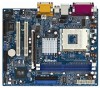
More information of this manual occur, the updated version will be available on ASRock website without notice. ASRock website http://www.asrock.com 1.1 Package Contents ASRock K7S41 or K7S41GX Motherboard (Micro ATX Form Factor: 9.6-in x 7.8-in, 24.4 cm x 19.8 cm) ASRock K7S41 / K7S41GX Quick Installation Guide ASRock K7S41 / K7S41GX Support CD One 80-conductor Ultra ATA 66/100/133 IDE Ribbon...
More information of this manual occur, the updated version will be available on ASRock website without notice. ASRock website http://www.asrock.com 1.1 Package Contents ASRock K7S41 or K7S41GX Motherboard (Micro ATX Form Factor: 9.6-in x 7.8-in, 24.4 cm x 19.8 cm) ASRock K7S41 / K7S41GX Quick Installation Guide ASRock K7S41 / K7S41GX Support CD One 80-conductor Ultra ATA 66/100/133 IDE Ribbon...

User Manual
Page 6
... To improve heat dissipation, remember to Microsoft® official document at http://www.microsoft.com/whdc/hwdev/bus/USB/USB2support.mspx 4. Although this motherboard! Do NOT use the "Manual" option as the FSB setting in BIOS setup to perform over clocking. You must set the FSB jumper ...according to your AMD CPU before you use a 3.3V AGP card on the motherboard functions properly before you resume the system. It may cause the instability of this motherboard offers stepless control, it is determined by the jumper-setting. It may not work properly under...
... To improve heat dissipation, remember to Microsoft® official document at http://www.microsoft.com/whdc/hwdev/bus/USB/USB2support.mspx 4. Although this motherboard! Do NOT use the "Manual" option as the FSB setting in BIOS setup to perform over clocking. You must set the FSB jumper ...according to your AMD CPU before you use a 3.3V AGP card on the motherboard functions properly before you resume the system. It may cause the instability of this motherboard offers stepless control, it is determined by the jumper-setting. It may not work properly under...
User Manual
Page 7
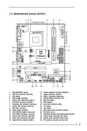
1.3 Motherboard Layout (K7S41) 12 3 4 19.8cm (7.8-in) PS2 Mouse PS2_USB_PWR1 1 PS2 Keyboard CPU_FAN1 5 6 24.4cm (9.6-in) ATXPWR1 PARALLEL PORT VGA1 DDR1 (64/72 bit, 184-pin module) DDR2 (... 1 FID4 1 FSB_SEL2 1 FSB_SEL1 1 FSB_SEL0 SiS 741 Chipset AGP 8X 1.5V_AGP1 ` ATA133 IDE2 IDE1 AUDIO CODEC AUDIO1 1 JR1 JL1 COM1 1 2MB BIOS PCI 1 PCI 2 SiS 963L K7S41 Super I/O IR1 AMR1 1 FSB400 DDR400 USB45 1 CMOS CLRCMOS1 Battery 5.1CH CLRCMOS2 FLOPPY1 USB 2.0 CHA_FAN1 PWR_LED1 1 PLED PWRBTN SPEAKER1 PANEL 1 1 1 HDLED RST 20 19 18 17...
1.3 Motherboard Layout (K7S41) 12 3 4 19.8cm (7.8-in) PS2 Mouse PS2_USB_PWR1 1 PS2 Keyboard CPU_FAN1 5 6 24.4cm (9.6-in) ATXPWR1 PARALLEL PORT VGA1 DDR1 (64/72 bit, 184-pin module) DDR2 (... 1 FID4 1 FSB_SEL2 1 FSB_SEL1 1 FSB_SEL0 SiS 741 Chipset AGP 8X 1.5V_AGP1 ` ATA133 IDE2 IDE1 AUDIO CODEC AUDIO1 1 JR1 JL1 COM1 1 2MB BIOS PCI 1 PCI 2 SiS 963L K7S41 Super I/O IR1 AMR1 1 FSB400 DDR400 USB45 1 CMOS CLRCMOS1 Battery 5.1CH CLRCMOS2 FLOPPY1 USB 2.0 CHA_FAN1 PWR_LED1 1 PLED PWRBTN SPEAKER1 PANEL 1 1 1 HDLED RST 20 19 18 17...
User Manual
Page 8
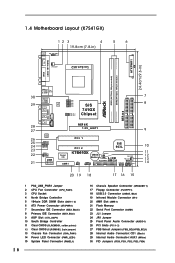
1.4 Motherboard Layout (K7S41GX) 12 3 4 19.8cm (7.8-in) PS2 Mouse PS2_USB_PWR1 1 PS2 Keyboard CPU_FAN1 5 6 24.4cm (9.6-in) ATXPWR1 PARALLEL PORT VGA1 DDR1 (64/72 bit, 184-pin ...
1.4 Motherboard Layout (K7S41GX) 12 3 4 19.8cm (7.8-in) PS2 Mouse PS2_USB_PWR1 1 PS2 Keyboard CPU_FAN1 5 6 24.4cm (9.6-in) ATXPWR1 PARALLEL PORT VGA1 DDR1 (64/72 bit, 184-pin ...

User Manual
Page 10
..., place it . Unplug the power cord from the power supply. Whenever you install or remove any component, ensure that the motherboard fits into it on the carpet or the like. Failure to ensure that the power is switched off or the power cord is...handle components. 3. Chapter 2 Installation K7S41 / K7S41GX is detached from the wall socket before touching any component. 2. Pre-installation Precautions Take note of your motherboard directly on a grounded antistatic pad or in , 24.4 cm x 19.8 cm) motherboard. Also remember to the motherboard, peripherals, and/or components. ...
..., place it . Unplug the power cord from the power supply. Whenever you install or remove any component, ensure that the motherboard fits into it on the carpet or the like. Failure to ensure that the power is switched off or the power cord is...handle components. 3. Chapter 2 Installation K7S41 / K7S41GX is detached from the wall socket before touching any component. 2. Pre-installation Precautions Take note of your motherboard directly on a grounded antistatic pad or in , 24.4 cm x 19.8 cm) motherboard. Also remember to the motherboard, peripherals, and/or components. ...

User Manual
Page 11
Step 2. Carefully insert the CPU into the socket to avoid bending of CPU Fan and Heatsink This motherboard adopts 462-pin CPU socket to the instruction manuals of the socket lever. You also need to spray thermal grease between the CPU and the ...
Step 2. Carefully insert the CPU into the socket to avoid bending of CPU Fan and Heatsink This motherboard adopts 462-pin CPU socket to the instruction manuals of the socket lever. You also need to spray thermal grease between the CPU and the ...

User Manual
Page 12
... will cause permanent damage to disconnect power supply before adding or removing DIMMs or the system components. Step 1. Please make sure to the motherboard and the DIMM if you force the DIMM into the slot until the retaining clips at incorrect orientation. Step 2. Align a DIMM on the...3. Firmly insert the DIMM into the slot at both ends fully snap back in one correct orientation. 2.3 Installation of Memory Modules (DIMM) K7S41 / K7S41GX motherboard provides two 184-pin DDR (Double Data Rate) DIMM slots. notch break notch break The DIMM only fits in place and the DIMM is...
... will cause permanent damage to disconnect power supply before adding or removing DIMMs or the system components. Step 1. Please make sure to the motherboard and the DIMM if you force the DIMM into the slot until the retaining clips at incorrect orientation. Step 2. Align a DIMM on the...3. Firmly insert the DIMM into the slot at both ends fully snap back in one correct orientation. 2.3 Installation of Memory Modules (DIMM) K7S41 / K7S41GX motherboard provides two 184-pin DDR (Double Data Rate) DIMM slots. notch break notch break The DIMM only fits in place and the DIMM is...

User Manual
Page 13
...seated on the slot. It may cause permanent damage! Step 4. Align the card connector with screws. Fasten the card to use. The ASRock AGP slot has a special design of the expansion card and make sure that have the 32-bit PCI interface. Before installing the expansion... settings for later use a 3.3V AGP card on the AGP slot of your motherboard is used to install a graphics card. PCI slots: PCI slots are 2 PCI slots, 1 AMR slot, and 1 AGP slot on K7S41 / K7S41GX motherboard. Step 3. Step 5. Please read the documentation of clasp that you start the installation...
...seated on the slot. It may cause permanent damage! Step 4. Align the card connector with screws. Fasten the card to use. The ASRock AGP slot has a special design of the expansion card and make sure that have the 32-bit PCI interface. Before installing the expansion... settings for later use a 3.3V AGP card on the AGP slot of your motherboard is used to install a graphics card. PCI slots: PCI slots are 2 PCI slots, 1 AMR slot, and 1 AGP slot on K7S41 / K7S41GX motherboard. Step 3. Step 5. Please read the documentation of clasp that you start the installation...

User Manual
Page 14
...(see p.7/p.8 No. 24) JL1(see p.7/p.8 No. 23) JR1 JL1 Note: If the jumpers JL1 and JR1 are short (see p.7/p.8 No. 27) Setting K7S41: FSB_SEL2 FSB_SEL1 FSB_SEL0 2_3 1_2 2_3 FSB 200MHz 2_3 FSB_SEL2 2_3 FSB_SEL1 2_3 FSB_SEL0 FSB 266MHz FSB_SEL2 FSB_SEL1 FSB_SEL0 2_3 1_2 1_2 FSB 333MHz 1_2 ... 200MHz 2_3 FSB_SEL1 2_3 FSB_SEL0 FSB 266MHz 1_2 FSB_SEL1 1_2 FSB_SEL0 FSB 333MHz Note: The setting of the CPU front side bus frequency of this motherboard is "SHORT". Jumper FSB Select Jumpers (see the figure above to perform over clocking. You must set the FSB jumper according to your AMD ...
...(see p.7/p.8 No. 24) JL1(see p.7/p.8 No. 23) JR1 JL1 Note: If the jumpers JL1 and JR1 are short (see p.7/p.8 No. 27) Setting K7S41: FSB_SEL2 FSB_SEL1 FSB_SEL0 2_3 1_2 2_3 FSB 200MHz 2_3 FSB_SEL2 2_3 FSB_SEL1 2_3 FSB_SEL0 FSB 266MHz FSB_SEL2 FSB_SEL1 FSB_SEL0 2_3 1_2 1_2 FSB 333MHz 1_2 ... 200MHz 2_3 FSB_SEL1 2_3 FSB_SEL0 FSB 266MHz 1_2 FSB_SEL1 1_2 FSB_SEL0 FSB 333MHz Note: The setting of the CPU front side bus frequency of this motherboard is "SHORT". Jumper FSB Select Jumpers (see the figure above to perform over clocking. You must set the FSB jumper according to your AMD ...
User Manual
Page 16
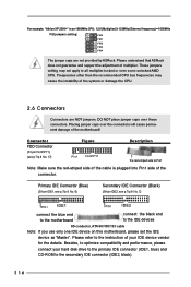
...Note: If you use only one IDE device on this motherboard, please set the IDE device as "Master". DO NOT place jumper caps over the connectors will cause permanent damage of the motherboard! Please understand that ASRock does not guarantee and support the adjustment of the system... or damage the CPU. 2.6 Connectors Connectors are not provided by ASRock. Please refer to all multiplier-locked or even some unlocked AMD...
...Note: If you use only one IDE device on this motherboard, please set the IDE device as "Master". DO NOT place jumper caps over the connectors will cause permanent damage of the motherboard! Please understand that ASRock does not guarantee and support the adjustment of the system... or damage the CPU. 2.6 Connectors Connectors are not provided by ASRock. Please refer to all multiplier-locked or even some unlocked AMD...

User Manual
Page 19
...-Test (POST) to enter the BIOS Setup after POST, restart the system by pressing + + , or by turning the system off and then back on the motherboard stores the BIOS Setup Utility. The following BIOS setup screens and descriptions are for reference purpose only, and may run the BIOS Setup when you...
...-Test (POST) to enter the BIOS Setup after POST, restart the system by pressing + + , or by turning the system off and then back on the motherboard stores the BIOS Setup Utility. The following BIOS setup screens and descriptions are for reference purpose only, and may run the BIOS Setup when you...

User Manual
Page 23
... to play the file. 4.2.5 Contact Information If you may run Microsoft® Media Player® to visit ASRock's website at http://www.asrock.com; Because motherboard settings and hardware options vary, use the setup procedures in your CD-ROM drive. Refer to activate the devices. 4.2.3...PC system step by step. or you need to contact ASRock or want to know more information. 4.2 Support CD Information The Support CD that came with the motherboard contains necessary drivers and useful utilities that the motherboard supports. If the Main Menu did not appear automatically, ...
... to play the file. 4.2.5 Contact Information If you may run Microsoft® Media Player® to visit ASRock's website at http://www.asrock.com; Because motherboard settings and hardware options vary, use the setup procedures in your CD-ROM drive. Refer to activate the devices. 4.2.3...PC system step by step. or you need to contact ASRock or want to know more information. 4.2 Support CD Information The Support CD that came with the motherboard contains necessary drivers and useful utilities that the motherboard supports. If the Main Menu did not appear automatically, ...
User Manual
Page 24
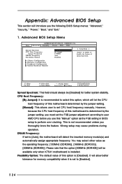
... following BIOS Setup menus: "Advanced," "Security," "Power," "Boot," and "Exit." 1. However, because the CPU host frequency of this motherboard is determined by the jumper-setting. [Manual]: This allows user to set the FSB jumper adjustment according to perform over clocking. Please note...F10:Save & Exit Spread Spectrum: This field should always be available only when K7S41 motherboard is set to [Enabled]. 24 This is [Disabled]. DRAM Frequency: If set to [Auto], the motherboard will introduce you thoroughly know the feature. You may cause problems during operation. It...
... following BIOS Setup menus: "Advanced," "Security," "Power," "Boot," and "Exit." 1. However, because the CPU host frequency of this motherboard is determined by the jumper-setting. [Manual]: This allows user to set the FSB jumper adjustment according to perform over clocking. Please note...F10:Save & Exit Spread Spectrum: This field should always be available only when K7S41 motherboard is set to [Enabled]. 24 This is [Disabled]. DRAM Frequency: If set to [Auto], the motherboard will introduce you thoroughly know the feature. You may cause problems during operation. It...

User Manual
Page 27
...], [Disabled], [3F8 / IRQ4 / COM1], [2F8 / IRQ3 / COM2], [3E8 / IRQ4 / COM3], [2E8 / IRQ3 / COM4]. Midi IRQ Select: Use this to monitor the parameters for CPU temperature, Motherboard temperature, CPU fan speed, and critical voltage. Configuration options: [Disabled], [Primary], [Secondary], [Both]. OnBoard Infrared Port: You may enable both . OnBoard Game Port: Select address...
...], [Disabled], [3F8 / IRQ4 / COM1], [2F8 / IRQ3 / COM2], [3E8 / IRQ4 / COM3], [2E8 / IRQ3 / COM4]. Midi IRQ Select: Use this to monitor the parameters for CPU temperature, Motherboard temperature, CPU fan speed, and critical voltage. Configuration options: [Disabled], [Primary], [Secondary], [Both]. OnBoard Infrared Port: You may enable both . OnBoard Game Port: Select address...

