RAID Installation Guide
Page 2
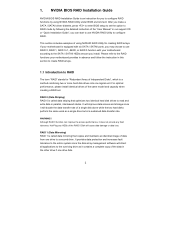
... RAID 0 function can start to use NVIDIA RAID Utility to use RAID 0, RAID 1, RAID 0+1, JBOD, or RAID 5 function with your motherboard is a method combining two or more hard disk drives into one logical unit. Hot-Plug any fault tolerance. This section includes examples of using... NVIDIA RAID Utility under BIOS environment. Please refer to the RAID functions your motherboard provides in advance and follow the instruction in this section to create RAID arrays. 1.1 Introduction to RAID The term "RAID" stands for...
... RAID 0 function can start to use NVIDIA RAID Utility to use RAID 0, RAID 1, RAID 0+1, JBOD, or RAID 5 function with your motherboard is a method combining two or more hard disk drives into one logical unit. Hot-Plug any fault tolerance. This section includes examples of using... NVIDIA RAID Utility under BIOS environment. Please refer to the RAID functions your motherboard provides in advance and follow the instruction in this section to create RAID arrays. 1.1 Introduction to RAID The term "RAID" stands for...
RAID Installation Guide
Page 5
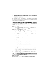
... you install OS on IDE HDD, please skip step 1 and 2. STEP 3: Set Up BIOS. Then you install. Insert the ASRock Support CD into your system. (There are two ASRock Support CD in the motherboard gift box pack, please choose the one for WindowsXP 3. When you see these messages, Please choose: 1. Generate RAID Driver...
... you install OS on IDE HDD, please skip step 1 and 2. STEP 3: Set Up BIOS. Then you install. Insert the ASRock Support CD into your system. (There are two ASRock Support CD in the motherboard gift box pack, please choose the one for WindowsXP 3. When you see these messages, Please choose: 1. Generate RAID Driver...
RAID Installation Guide
Page 7
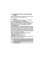
... in the following path in the Support CD: .. \ RAID Installation Guide 7 NVIDIA® RAID drivers are in the following path in the motherboard gift box pack, please choose the one for proper configuration. If you install Windows® VistaTM / Windows® VistaTM 64-bit on IDE ...or rebuild) RAID functions on SATA / SATAII HDDs, you still need to check the RAID installation guide in BIOS first. " page, please insert the ASRock Support CD into your system. Then, please set RAID configuration. STEP 1: Set Up BIOS. Set the "SATA Operation Mode" option to install Windows?...
... in the following path in the Support CD: .. \ RAID Installation Guide 7 NVIDIA® RAID drivers are in the following path in the motherboard gift box pack, please choose the one for proper configuration. If you install Windows® VistaTM / Windows® VistaTM 64-bit on IDE ...or rebuild) RAID functions on SATA / SATAII HDDs, you still need to check the RAID installation guide in BIOS first. " page, please insert the ASRock Support CD into your system. Then, please set RAID configuration. STEP 1: Set Up BIOS. Set the "SATA Operation Mode" option to install Windows?...
RAID Installation Guide
Page 12
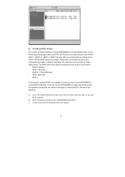
... to show you plan to the system BIOS and make sure that the drives that you install. JBOD: Spanning - If your motherboard is equipped with your motherboard provides in advance and follow the instruction in this section, we take RAID 0 for creating RAID arrays. RAID 1: Mirroring - ...create RAID arrays. B. Creating RAID Arrays This section includes examples of creating RAID 0. Please refer to the RAID functions your motherboard according to the SATA / SATAII HDDs amount you want to use NVRAIDMAN to create other RAID arrays, the operation procedures are RAID enabled...
... to show you plan to the system BIOS and make sure that the drives that you install. JBOD: Spanning - If your motherboard is equipped with your motherboard provides in advance and follow the instruction in this section, we take RAID 0 for creating RAID arrays. RAID 1: Mirroring - ...create RAID arrays. B. Creating RAID Arrays This section includes examples of creating RAID 0. Please refer to the RAID functions your motherboard according to the SATA / SATAII HDDs amount you want to use NVRAIDMAN to create other RAID arrays, the operation procedures are RAID enabled...
User Manual
Page 2
...transcribed, transmitted, or translated in any language, in Perchlorate Best Management Practices (BMP) regulations passed by ASRock. CALIFORNIA, USA ONLY The Lithium battery adopted on this motherboard contains Perchlorate, a toxic substance controlled in any form or by the purchaser for a particular purpose.... With respect to the contents of this manual, ASRock does not provide warranty of any interference received, ...
...transcribed, transmitted, or translated in any language, in Perchlorate Best Management Practices (BMP) regulations passed by ASRock. CALIFORNIA, USA ONLY The Lithium battery adopted on this motherboard contains Perchlorate, a toxic substance controlled in any form or by the purchaser for a particular purpose.... With respect to the contents of this manual, ASRock does not provide warranty of any interference received, ...

User Manual
Page 3
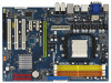
...Audio Function Operation Guide 29 2.8 Jumpers Setup 30 2.9 Onboard Headers and Connectors 31 2.10 HDMI_SPDIF Header Connection Guide 37 2.11 eSATAII Interface Introduction (Only for K10N78-1394) ......... 38 2.12 SATAII Hard Disk Setup Guide 41 2.13 Serial ATA (SATA) / Serial ATAII (SATAII) Hard Disks Installation 42 2.14 Hot...1080p Blu-ray (BD) / HD-DVD Playback Support 11 1.4 Passed 1080p Blu-ray (BD) / HD-DVD Films in Our Lab Test ... 12 1.5 Motherboard Layout (K10N78-1394 13 1.6 Motherboard Layout (K10N78 14 1.7 I/O Panel (K10N78-1394 15 1.8 I/O Panel (K10N78 16 2 . Contents 1 .
...Audio Function Operation Guide 29 2.8 Jumpers Setup 30 2.9 Onboard Headers and Connectors 31 2.10 HDMI_SPDIF Header Connection Guide 37 2.11 eSATAII Interface Introduction (Only for K10N78-1394) ......... 38 2.12 SATAII Hard Disk Setup Guide 41 2.13 Serial ATA (SATA) / Serial ATAII (SATAII) Hard Disks Installation 42 2.14 Hot...1080p Blu-ray (BD) / HD-DVD Playback Support 11 1.4 Passed 1080p Blu-ray (BD) / HD-DVD Films in Our Lab Test ... 12 1.5 Motherboard Layout (K10N78-1394 13 1.6 Motherboard Layout (K10N78 14 1.7 I/O Panel (K10N78-1394 15 1.8 I/O Panel (K10N78 16 2 . Contents 1 .
User Manual
Page 5
... updated, the content of this manual will be subject to the hardware installation. ASRock website http://www.asrock.com If you for purchasing ASRock K10N78-1394 / K10N78 motherboard, a reliable motherboard produced under ASRock's consistently stringent quality control. www.asrock.com/support/index.asp 1.1 Package Contents ASRock K10N78-1394 / K10N78 Motherboard (ATX Form Factor: 12.0-in x 8.4-in Floppy Drive Two Serial ATA (SATA) Data...
... updated, the content of this manual will be subject to the hardware installation. ASRock website http://www.asrock.com If you for purchasing ASRock K10N78-1394 / K10N78 motherboard, a reliable motherboard produced under ASRock's consistently stringent quality control. www.asrock.com/support/index.asp 1.1 Package Contents ASRock K10N78-1394 / K10N78 Motherboard (ATX Form Factor: 12.0-in x 8.4-in Floppy Drive Two Serial ATA (SATA) Data...
User Manual
Page 8
... memory support list on this motherbord, the system bus speed will be HT1.0 (2000 MT/s). ASRock OC Tuner (see CAUTION 16) - Hybrid Booster: - Chassis Fan Tachometer - Voltage Monitoring: +12V, +5V, +3.3V, CPU Vcore OS - This motherboard supports Untied Overclocking Technology. Please read the installation guide of memory modules on our website for...
... memory support list on this motherbord, the system bus speed will be HT1.0 (2000 MT/s). ASRock OC Tuner (see CAUTION 16) - Hybrid Booster: - Chassis Fan Tachometer - Voltage Monitoring: +12V, +5V, +3.3V, CPU Vcore OS - This motherboard supports Untied Overclocking Technology. Please read the installation guide of memory modules on our website for...
User Manual
Page 9
.... Please check the table on the driver from NVIDIA® and it may be used to change. This motherboard supports eSATAII interface, the external SATAII specification. ASRock website http://www.asrock.com 14. The voltage regulator can also connect SATA hard disk to get the best system performance under Microsoft&#... the passed 1080p Blu-ray (BD) / HD-DVD films in the future. For audio output, this motherboard supports both stereo and mono modes. You can reduce the number of ASRock WiFi-802.11g or WiFi-802.11n module. In other words, it to improve efficiency when the CPU ...
.... Please check the table on the driver from NVIDIA® and it may be used to change. This motherboard supports eSATAII interface, the external SATAII specification. ASRock website http://www.asrock.com 14. The voltage regulator can also connect SATA hard disk to get the best system performance under Microsoft&#... the passed 1080p Blu-ray (BD) / HD-DVD films in the future. For audio output, this motherboard supports both stereo and mono modes. You can reduce the number of ASRock WiFi-802.11g or WiFi-802.11n module. In other words, it to improve efficiency when the CPU ...
User Manual
Page 10
...18. Although this function for all CPU/DRAM configurations. To improve heat dissipation, remember to disable this motherboard offers stepless control, it back again. This motherboard supports ASRock AM2 Boost overclocking technology for the operation procedures of Intelligent Energy Saver. You may not be applicative to...the BIOS setup in the BIOS setup, the memory performance will improve up to 12.5%, but the effect still depends on the motherboard functions properly and unplug the power cord, then plug it is not recommended to perform over-clocking. However, we can not...
...18. Although this function for all CPU/DRAM configurations. To improve heat dissipation, remember to disable this motherboard offers stepless control, it back again. This motherboard supports ASRock AM2 Boost overclocking technology for the operation procedures of Intelligent Energy Saver. You may not be applicative to...the BIOS setup in the BIOS setup, the memory performance will improve up to 12.5%, but the effect still depends on the motherboard functions properly and unplug the power cord, then plug it is not recommended to perform over-clocking. However, we can not...
User Manual
Page 11
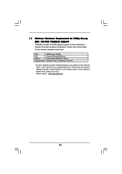
ASRock website http://www.asrock.com 11 If you install Windows® XP / XP 64-bit OS, the function of 1080p Blu-ray (BD) / HD-DVD playback is only supported ... requirement. Please refer to below table for 1080p Blu-ray (BD) / HD-DVD Playback Support 1080p Blu-ray (BD) / HD-DVD playback support on this motherboard requires the proper hardware configuration.
ASRock website http://www.asrock.com 11 If you install Windows® XP / XP 64-bit OS, the function of 1080p Blu-ray (BD) / HD-DVD playback is only supported ... requirement. Please refer to below table for 1080p Blu-ray (BD) / HD-DVD Playback Support 1080p Blu-ray (BD) / HD-DVD playback support on this motherboard requires the proper hardware configuration.

User Manual
Page 13
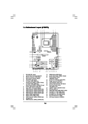
... (ATXPWR1) 18 SATAII Connector (SATAII_3 (PORT2), Red) 36 eSATAII Connector (eSATAII_TOP, Orange) 19 NVIDIA GeForce 8200 Chipset 13 1.5 Motherboard Layout (K10N78-1394) 12 3 45 67 21.3cm (8.4-in) 1 PS2_USB_PW1 PS2 Mouse PS2 Keyboard AM2+ FSB2.6GHz DVI_CON1 VGA1 ATX12V1 DDRII_3 (...CPU_FAN1 140W CPU PCI Express 2.0 Super I/O PCIE2 PCIE3 RAID 1 FRONT_1394 HDMI_SPDIF1 1 AUDIO CODEC USB/WIFI HD_AUDIO1 CD1 1 IR1 1 FLOPPY1 PCIE1 K10N78-1394 CLRCMOS1 1 CMOS BATTERY SATAII_1 (PORT0) SATAII_3 (PORT2) SATAII_5 (PORT4) SATAII_2 (PORT1) SATAII_4 (PORT3) SATAII_6 (PORT5) PCI1 RoHS ...
... (ATXPWR1) 18 SATAII Connector (SATAII_3 (PORT2), Red) 36 eSATAII Connector (eSATAII_TOP, Orange) 19 NVIDIA GeForce 8200 Chipset 13 1.5 Motherboard Layout (K10N78-1394) 12 3 45 67 21.3cm (8.4-in) 1 PS2_USB_PW1 PS2 Mouse PS2 Keyboard AM2+ FSB2.6GHz DVI_CON1 VGA1 ATX12V1 DDRII_3 (...CPU_FAN1 140W CPU PCI Express 2.0 Super I/O PCIE2 PCIE3 RAID 1 FRONT_1394 HDMI_SPDIF1 1 AUDIO CODEC USB/WIFI HD_AUDIO1 CD1 1 IR1 1 FLOPPY1 PCIE1 K10N78-1394 CLRCMOS1 1 CMOS BATTERY SATAII_1 (PORT0) SATAII_3 (PORT2) SATAII_5 (PORT4) SATAII_2 (PORT1) SATAII_4 (PORT3) SATAII_6 (PORT5) PCI1 RoHS ...
User Manual
Page 14
1.6 Motherboard Layout (K10N78) 12 3 45 21.3cm (8.4-in) 1 PS2_USB_PW1 67 PS2 Mouse PS2 Keyboard AM2+ FSB2.6GHz DVI_CON1 VGA1 USB 2.0 T: USB4 B: USB5 USB 2.0 T: USB2 B: USB3 USB 2.0 T: USB0 B: USB1 ... 29 28 27 1 COM1 LAN PHY CPU_FAN1 140W CPU PCI Express 2.0 Super I/O PCIE2 PCIE3 RAID HDMI_SPDIF1 1 AUDIO CODEC USB/WIFI HD_AUDIO1 CD1 1 IR1 1 FLOPPY1 PCIE1 K10N78 CLRCMOS1 1 CMOS BATTERY SATAII_1 (PORT0) SATAII_3 (PORT2) SATAII_5 (PORT4) SATAII_2 (PORT1) SATAII_4 (PORT3) SATAII_6 (PORT5) PCI1 RoHS PCI2 PCI3 NVIDIA GeForce 8200 Chipset CHA_FAN1 SPEAKER1...
1.6 Motherboard Layout (K10N78) 12 3 45 21.3cm (8.4-in) 1 PS2_USB_PW1 67 PS2 Mouse PS2 Keyboard AM2+ FSB2.6GHz DVI_CON1 VGA1 USB 2.0 T: USB4 B: USB5 USB 2.0 T: USB2 B: USB3 USB 2.0 T: USB0 B: USB1 ... 29 28 27 1 COM1 LAN PHY CPU_FAN1 140W CPU PCI Express 2.0 Super I/O PCIE2 PCIE3 RAID HDMI_SPDIF1 1 AUDIO CODEC USB/WIFI HD_AUDIO1 CD1 1 IR1 1 FLOPPY1 PCIE1 K10N78 CLRCMOS1 1 CMOS BATTERY SATAII_1 (PORT0) SATAII_3 (PORT2) SATAII_5 (PORT4) SATAII_2 (PORT1) SATAII_4 (PORT3) SATAII_6 (PORT5) PCI1 RoHS PCI2 PCI3 NVIDIA GeForce 8200 Chipset CHA_FAN1 SPEAKER1...
User Manual
Page 17
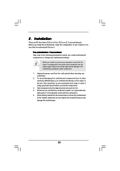
... is switched off or the power cord is an ATX form factor (12.0-in x 8.4-in the bag that the motherboard fits into the screw holes to secure the motherboard to the motherboard, peripherals, and/or components. 1. Also remember to ensure that comes with the component. 5. Unplug the power cord ...from the power supply. When placing screws into it on the carpet or the like. Before you install the motherboard, study the configuration of the following precautions before you install or remove any component, place it . Before you handle components. 3.
... is switched off or the power cord is an ATX form factor (12.0-in x 8.4-in the bag that the motherboard fits into the screw holes to secure the motherboard to the motherboard, peripherals, and/or components. 1. Also remember to ensure that comes with the component. 5. Unplug the power cord ...from the power supply. When placing screws into it on the carpet or the like. Before you install the motherboard, study the configuration of the following precautions before you install or remove any component, place it . Before you handle components. 3.
User Manual
Page 18
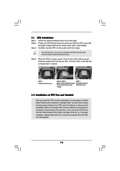
... and the heatsink are securely fastened and in one correct orientation. Make sure that it fits in place. DO NOT force the CPU into this motherboard, it is in place, press it firmly on the side tab to dissipate heat. Then connect the CPU fan to improve heat dissipation. The lever...
... and the heatsink are securely fastened and in one correct orientation. Make sure that it fits in place. DO NOT force the CPU into this motherboard, it is in place, press it firmly on the side tab to dissipate heat. Then connect the CPU fan to improve heat dissipation. The lever...
User Manual
Page 19
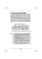
... modules, for optimal compatibility and reliability, it is unable to install identical DDR2 DIMM pair in the slots of Memory Modules (DIMM) This motherboard provides four 240-pin DDR2 (Double Data Rate 2) DIMM slots, and supports Dual Channel Memory Technology. If a pair of memory modules is... DDR memory module into DDR2 slot; see p.13/14 No.7), so that Dual Channel Memory Technology can be damaged. 19 otherwise, this motherboard, it is recommended to the Dual Channel Memory Configuration Table below. If only one memory module or three memory modules are installed in all ...
... modules, for optimal compatibility and reliability, it is unable to install identical DDR2 DIMM pair in the slots of Memory Modules (DIMM) This motherboard provides four 240-pin DDR2 (Double Data Rate 2) DIMM slots, and supports Dual Channel Memory Technology. If a pair of memory modules is... DDR memory module into DDR2 slot; see p.13/14 No.7), so that Dual Channel Memory Technology can be damaged. 19 otherwise, this motherboard, it is recommended to the Dual Channel Memory Configuration Table below. If only one memory module or three memory modules are installed in all ...
User Manual
Page 20
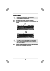
... a DIMM on the slot such that the notch on the DIMM matches the break on the slot. Step 2. Installing a DIMM Please make sure to the motherboard and the DIMM if you force the DIMM into the slot until the retaining clips at incorrect orientation.
... a DIMM on the slot such that the notch on the DIMM matches the break on the slot. Step 2. Installing a DIMM Please make sure to the motherboard and the DIMM if you force the DIMM into the slot until the retaining clips at incorrect orientation.
User Manual
Page 21
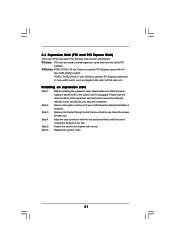
...width cards, such as Gigabit LAN card, SATA2 card, etc. Step 5. PCIE slots: PCIE1 (PCIE x16 slot; Green) is completely seated on this motherboard. Keep the screws for later use . Step 2. Step 3. Step 4. Step 6. Remove the bracket facing the slot that you start the installation. ...Fasten the card to the chassis with screws. Remove the system unit cover (if your motherboard is already installed in a chassis). PCIE2 / PCIE3 (PCIE x1 slot; Replace the system cover. 21 Installing an expansion card Step 1. 2.4 ...
...width cards, such as Gigabit LAN card, SATA2 card, etc. Step 5. PCIE slots: PCIE1 (PCIE x16 slot; Green) is completely seated on this motherboard. Keep the screws for later use . Step 2. Step 3. Step 4. Step 6. Remove the bracket facing the slot that you start the installation. ...Fasten the card to the chassis with screws. Remove the system unit cover (if your motherboard is already installed in a chassis). PCIE2 / PCIE3 (PCIE x1 slot; Replace the system cover. 21 Installing an expansion card Step 1. 2.4 ...
User Manual
Page 22
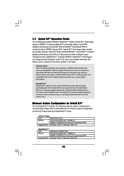
...; discrete GPU when combined with other OS. Installing NVIDIA® Hybrid SLITM-enabled graphics card into NVIDIA® Hybrid SLITM-enabled motherboard allows you to switch off the discrete GPU not only lowers the total system power consumption for GeForce® Boost mode and HybridPowerTM...Channel DDR2 667, 1024MB x 2 256MB or 512MB shared memory for the driver update in the future. Please visit our website for motherboard GPU Windows® VistaTM or Windows® VistaTM 64 22 HybridPowerTM HybridPowerTM enables users to enjoy additive performance. Switching off the discrete GPU...
...; discrete GPU when combined with other OS. Installing NVIDIA® Hybrid SLITM-enabled graphics card into NVIDIA® Hybrid SLITM-enabled motherboard allows you to switch off the discrete GPU not only lowers the total system power consumption for GeForce® Boost mode and HybridPowerTM...Channel DDR2 667, 1024MB x 2 256MB or 512MB shared memory for the driver update in the future. Please visit our website for motherboard GPU Windows® VistaTM or Windows® VistaTM 64 22 HybridPowerTM HybridPowerTM enables users to enjoy additive performance. Switching off the discrete GPU...
User Manual
Page 23
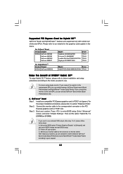
GeForce® Boost Step 1. For the proper installation procedures, please refer to the motherboard GPU, you can choose GeForce® Boost mode (Boost Performance) only. Step 3. C. For users using single monitor: If you connect the monitor to PCIE1 slot (...
GeForce® Boost Step 1. For the proper installation procedures, please refer to the motherboard GPU, you can choose GeForce® Boost mode (Boost Performance) only. Step 3. C. For users using single monitor: If you connect the monitor to PCIE1 slot (...

