
User Manual
Page 2
... CALIFORNIA, USA ONLY The Lithium battery adopted on this motherboard contains Perchlorate, a toxic substance controlled in this documentation are used only for a particular purpose. This device complies with Part 15 of ASRock Inc. When you discard the Lithium battery in California, ... the purchaser for any interference received, including interference that may apply, see www.dtsc.ca.gov/hazardouswaste/ perchlorate" ASRock Website: http://www.asrock.com With respect to the contents of this documentation may or may not be reproduced, transcribed, transmitted, or translated...
... CALIFORNIA, USA ONLY The Lithium battery adopted on this motherboard contains Perchlorate, a toxic substance controlled in this documentation are used only for a particular purpose. This device complies with Part 15 of ASRock Inc. When you discard the Lithium battery in California, ... the purchaser for any interference received, including interference that may apply, see www.dtsc.ca.gov/hazardouswaste/ perchlorate" ASRock Website: http://www.asrock.com With respect to the contents of this documentation may or may not be reproduced, transcribed, transmitted, or translated...

User Manual
Page 4
Contents Chapter 1 Introduction 1 1.1 Package Contents 1 1.2 Specifications 2 1.3 Motherboard Layout 5 1.4 I/O Panel 7 Chapter 2 Installation 9 2.1 Installing Memory Modules (SO-DIMM) 10 2.2 Expansion Slot (PCI Express Slot) 12 2.3 Jumpers Setup 13 2.4 Onboard Headers and Connectors 14 Chapter 3 Software and Utilities Operation 18 3.1 Installing Drivers 18 3.2 ASRock Live Update & APP Shop 19 3.2.1 UI Overview 19 3.2.2 Apps 20 3.2.3 BIOS & Drivers...
Contents Chapter 1 Introduction 1 1.1 Package Contents 1 1.2 Specifications 2 1.3 Motherboard Layout 5 1.4 I/O Panel 7 Chapter 2 Installation 9 2.1 Installing Memory Modules (SO-DIMM) 10 2.2 Expansion Slot (PCI Express Slot) 12 2.3 Jumpers Setup 13 2.4 Onboard Headers and Connectors 14 Chapter 3 Software and Utilities Operation 18 3.1 Installing Drivers 18 3.2 ASRock Live Update & APP Shop 19 3.2.1 UI Overview 19 3.2.2 Apps 20 3.2.3 BIOS & Drivers...

User Manual
Page 6
... installation guides. Chapter 4 contains the configuration guide of this motherboard, please visit our website for purchasing ASRock J3455B-ITX/J3355B-ITX motherboard, a reliable motherboard produced under ASRock's consistently stringent quality control. ASRock website http://www.asrock.com. 1.1 Package Contents • ASRock J3455B-ITX/J3355B-ITX Motherboard (Mini-ITX Form Factor) • ASRock J3455B-ITX/J3355B-ITX Quick Installation Guide • ASRock J3455B-ITX/J3355B-ITX Support CD • 2 x Serial ATA (SATA) Data Cables (Optional...
... installation guides. Chapter 4 contains the configuration guide of this motherboard, please visit our website for purchasing ASRock J3455B-ITX/J3355B-ITX motherboard, a reliable motherboard produced under ASRock's consistently stringent quality control. ASRock website http://www.asrock.com. 1.1 Package Contents • ASRock J3455B-ITX/J3355B-ITX Motherboard (Mini-ITX Form Factor) • ASRock J3455B-ITX/J3355B-ITX Quick Installation Guide • ASRock J3455B-ITX/J3355B-ITX Support CD • 2 x Serial ATA (SATA) Data Cables (Optional...
User Manual
Page 10
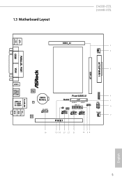
1.3 Motherboard Layout J3455B-ITX J3355B-ITX PS2 Mouse PS2 Keyboard AT X P W R 1 DDR3_B1 PARALLEL PORT COM1 DDR3_A1 1 2 CPU_FAN1 3 VGA1 HDMI1 Top: LINE IN Center: FRONT Bottom: MIC IN USB 2.0 T: USB0 USB 3.0 B: USB1 USB 3.0 T: USB3 B: USB4 RJ-45 LAN BIOS ROM CMOS Battery LAN AUDIO CODEC HD_AUDIO1 1 TPMS1 Front USB 3.0 4 RoHS 1 5 SATA3_2 SATA3_1 PANEL1 PLED PWRBTN HDLED RESET SPEAKER1 USB3_1_2 1 6 CI1 CLRMOS1 1 1 1 COM2 USB2_3 USB4_5 1 1 1 7 PCIE1 16 15 14 13 12 11 10 9 8 English 5
1.3 Motherboard Layout J3455B-ITX J3355B-ITX PS2 Mouse PS2 Keyboard AT X P W R 1 DDR3_B1 PARALLEL PORT COM1 DDR3_A1 1 2 CPU_FAN1 3 VGA1 HDMI1 Top: LINE IN Center: FRONT Bottom: MIC IN USB 2.0 T: USB0 USB 3.0 B: USB1 USB 3.0 T: USB3 B: USB4 RJ-45 LAN BIOS ROM CMOS Battery LAN AUDIO CODEC HD_AUDIO1 1 TPMS1 Front USB 3.0 4 RoHS 1 5 SATA3_2 SATA3_1 PANEL1 PLED PWRBTN HDLED RESET SPEAKER1 USB3_1_2 1 6 CI1 CLRMOS1 1 1 1 COM2 USB2_3 USB4_5 1 1 1 7 PCIE1 16 15 14 13 12 11 10 9 8 English 5

User Manual
Page 14
...ICs. • Whenever you uninstall any motherboard settings. • Make sure to unplug the power cord before you and damages to motherboard components. • In order to avoid damage from static electricity to the motherboard's components, NEVER place your chassis to do...• When placing screws to secure the motherboard to the chassis, please do so may damage the motherboard. 9 English J3455B-ITX J3355B-ITX Chapter 2 Installation This is a Mini-ITX form factor motherboard. Pre-installation Precautions Take note of your motherboard directly on a grounded anti-static pad or...
...ICs. • Whenever you uninstall any motherboard settings. • Make sure to unplug the power cord before you and damages to motherboard components. • In order to avoid damage from static electricity to the motherboard's components, NEVER place your chassis to do...• When placing screws to secure the motherboard to the chassis, please do so may damage the motherboard. 9 English J3455B-ITX J3355B-ITX Chapter 2 Installation This is a Mini-ITX form factor motherboard. Pre-installation Precautions Take note of your motherboard directly on a grounded anti-static pad or...

User Manual
Page 15
otherwise, this motherboard and SO-DIMM may be damaged. It will cause permanent damage to install a DDR or DDR2 memory module into the slot at incorrect orientation. 10 English 2.1 Installing Memory Modules (SO-DIMM) This motherboard provides two 204-pin DDR3/DDR3L (Double Data Rate 3) SO-DIMM slots. It is not allowed to the motherboard and the SO-DIMM if you force the SO-DIMM into a DDR3/DDR3L slot; The SO-DIMM only fits in one correct orientation.
otherwise, this motherboard and SO-DIMM may be damaged. It will cause permanent damage to install a DDR or DDR2 memory module into the slot at incorrect orientation. 10 English 2.1 Installing Memory Modules (SO-DIMM) This motherboard provides two 204-pin DDR3/DDR3L (Double Data Rate 3) SO-DIMM slots. It is not allowed to the motherboard and the SO-DIMM if you force the SO-DIMM into a DDR3/DDR3L slot; The SO-DIMM only fits in one correct orientation.

User Manual
Page 17
... the installation. PCIe slot: PCIE1 (PCIe 2.0 x16 slot) is set to "boot from Onboard VGA" as default even the user install a VGA card on the motherboard. Please read the documentation of the expansion card and make sure that the power supply is switched off or the power cord is 1 PCI Express...
... the installation. PCIe slot: PCIE1 (PCIe 2.0 x16 slot) is set to "boot from Onboard VGA" as default even the user install a VGA card on the motherboard. Please read the documentation of the expansion card and make sure that the power supply is switched off or the power cord is 1 PCI Express...

User Manual
Page 19
... to the reset switch on the chassis front panel. Press the reset switch to restart the computer if the computer freezes and fails to the motherboard. The front panel design may configure the way to the pin assignments below. Placing jumper caps over these headers and connectors. 2.4 Onboard Headers and Connectors...
... to the reset switch on the chassis front panel. Press the reset switch to restart the computer if the computer freezes and fails to the motherboard. The front panel design may configure the way to the pin assignments below. Placing jumper caps over these headers and connectors. 2.4 Onboard Headers and Connectors...

User Manual
Page 20
...-ITX J3355B-ITX Serial ATA3 Connectors (SATA3_1: see p.5, No. 5) (SATA3_2: see p.5, No. 9) IntA_P_D+ IntA_P_DGND IntA_P_SSTX+ IntA_P_SSTXGND IntA_P_SSRX+ IntA_P_SSRXVbus 1 Vbus IntA_P_SSRXIntA_P_SSRX+ GND IntA_P_SSTXIntA_P_SSTX+ GND IntA_P_DIntA_P_D+ ID Besides three USB 3.0 ports on the I /O panel, there are two headers on this motherboard..... 16) GND PRESENCE# MIC_RET OUT_RET 1 OUT2_L J_SENSE OUT2_R MIC2_R MIC2_L This header is one USB 2.0 port on this motherboard. Each USB 2.0 header can support two ports. English 15 Front Panel Audio Header (9-pin HD_AUDIO1) (see p.5, No...
...-ITX J3355B-ITX Serial ATA3 Connectors (SATA3_1: see p.5, No. 5) (SATA3_2: see p.5, No. 9) IntA_P_D+ IntA_P_DGND IntA_P_SSTX+ IntA_P_SSTXGND IntA_P_SSRX+ IntA_P_SSRXVbus 1 Vbus IntA_P_SSRXIntA_P_SSRX+ GND IntA_P_SSTXIntA_P_SSTX+ GND IntA_P_DIntA_P_D+ ID Besides three USB 3.0 ports on the I /O panel, there are two headers on this motherboard..... 16) GND PRESENCE# MIC_RET OUT_RET 1 OUT2_L J_SENSE OUT2_R MIC2_R MIC2_L This header is one USB 2.0 port on this motherboard. Each USB 2.0 header can support two ports. English 15 Front Panel Audio Header (9-pin HD_AUDIO1) (see p.5, No...

User Manual
Page 21
... chassis speaker to the "FrontMic" Tab in our manual and chassis manual to MIC2_L. Connect Ground (GND) to the ground pin. 12 24 1 13 This motherboard provides a 24-pin ATX power connector. GND FAN_VOLTAGE FAN_SPEED Please connect the CPU fan cable to the connector and match the black wire to Ground...
... chassis speaker to the "FrontMic" Tab in our manual and chassis manual to MIC2_L. Connect Ground (GND) to the ground pin. 12 24 1 13 This motherboard provides a 24-pin ATX power connector. GND FAN_VOLTAGE FAN_SPEED Please connect the CPU fan cable to the connector and match the black wire to Ground...

User Manual
Page 22
... DDTR#1 DDSR#1 CCTS#1 1 RRI#1 RRTS#1 GND TTXD1 DDCD#1 This COM1 header supports a serial port module. This feature requires a chassis with chassis intrusion detection design. J3455B-ITX J3355B-ITX Chassis Intrusion Header (2-pin CI1) (see p.5, No. 14) 1 GND Signal This motherboard supports CASE OPEN detection feature that detects if the chassis cove has been removed.
... DDTR#1 DDSR#1 CCTS#1 1 RRI#1 RRTS#1 GND TTXD1 DDCD#1 This COM1 header supports a serial port module. This feature requires a chassis with chassis intrusion detection design. J3455B-ITX J3355B-ITX Chassis Intrusion Header (2-pin CI1) (see p.5, No. 14) 1 GND Signal This motherboard supports CASE OPEN detection feature that detects if the chassis cove has been removed.

User Manual
Page 23
Chapter 3 Software and Utilities Operation 3.1 Installing Drivers The Support CD that comes with the motherboard contains necessary drivers and useful utilities that the motherboard supports. Please click Install All or follow the installation wizard to display the menu. Therefore, the ...locate and double click on the support CD driver page. Utilities Menu The Utilities Menu shows the application software that enhance the motherboard's features. Drivers Menu The drivers compatible to install those required drivers. To improve Windows 7 compatibility, please download and install...
Chapter 3 Software and Utilities Operation 3.1 Installing Drivers The Support CD that comes with the motherboard contains necessary drivers and useful utilities that the motherboard supports. Please click Install All or follow the installation wizard to display the menu. Therefore, the ...locate and double click on the support CD driver page. Utilities Menu The Utilities Menu shows the application software that enhance the motherboard's features. Drivers Menu The drivers compatible to install those required drivers. To improve Windows 7 compatibility, please download and install...

User Manual
Page 24
... LAN, XFast RAM and more . 19 English J3455B-ITX J3355B-ITX 3.2 ASRock Live Update & APP Shop The ASRock Live Update & APP Shop is an online store for purchasing and downloading software applications for your motherboard up to download apps from the ASRock Live Update & APP Shop. 3.2.1 UI Overview Category ... few clicks. Hot News: The hot news section displays the various latest news. You can optimize your system and keep your ASRock computer. Information Panel: The information panel in the center displays data about the currently selected category and allows users to visit the...
... LAN, XFast RAM and more . 19 English J3455B-ITX J3355B-ITX 3.2 ASRock Live Update & APP Shop The ASRock Live Update & APP Shop is an online store for purchasing and downloading software applications for your motherboard up to download apps from the ASRock Live Update & APP Shop. 3.2.1 UI Overview Category ... few clicks. Hot News: The hot news section displays the various latest news. You can optimize your system and keep your ASRock computer. Information Panel: The information panel in the center displays data about the currently selected category and allows users to visit the...

User Manual
Page 35
... up. Share Memory Configure the size of memory that is installed. Onboard HD Audio Enable/disable onboard HD audio. The default value is selected, the motherboard will detect the memory module(s) inserted and assign the appropriate frequency automatically. Front Panel Enable/disable front panel HD audio. 30 English 4.3.2 Chipset Configuration DRAM...
... up. Share Memory Configure the size of memory that is installed. Onboard HD Audio Enable/disable onboard HD audio. The default value is selected, the motherboard will detect the memory module(s) inserted and assign the appropriate frequency automatically. Front Panel Enable/disable front panel HD audio. 30 English 4.3.2 Chipset Configuration DRAM...

User Manual
Page 45
... Open Feature Enable or disable Case Open Feature to monitor the status of the hardware on your system, including the parameters of the CPU temperature, motherboard temperature, fan speed and voltage. Chassis Fan 1 Setting This allows you to set chassis fan 1's speed. The default value is [Full On]. Configuration options: [Full...
... Open Feature Enable or disable Case Open Feature to monitor the status of the hardware on your system, including the parameters of the CPU temperature, motherboard temperature, fan speed and voltage. Chassis Fan 1 Setting This allows you to set chassis fan 1's speed. The default value is [Full On]. Configuration options: [Full...

