
Intel Smart Response Installation Guide
Page 1
..., if you want to accelerate AND the SSD in Icon tray, lower right-hand corner of the screen. 4. Intel Smart Response Technology Installation Guide This motherboard supports Intel Smart Response Technology. You can find the UI setup instruction and the step by double-clicking RST Storage icon in system at this... system setup, including installing the OS to [RAID Mode]. For the new version RST driver, please check our website for the latest information: http://www.asrock.com * Before you use Enhanced or Maximized Mode. 6.
..., if you want to accelerate AND the SSD in Icon tray, lower right-hand corner of the screen. 4. Intel Smart Response Technology Installation Guide This motherboard supports Intel Smart Response Technology. You can find the UI setup instruction and the step by double-clicking RST Storage icon in system at this... system setup, including installing the OS to [RAID Mode]. For the new version RST driver, please check our website for the latest information: http://www.asrock.com * Before you use Enhanced or Maximized Mode. 6.

Intel Rapid Storage Guide
Page 12
... F2 or Delete to save the BIOS settings and exit the BIOS Setup program. Enable RAID in System BIOS Use the instructions included with your motherboard to enable RAID in the system BIOS, a RAID volume must be created, and the F6 installation method must be used to load the Intel®...
... F2 or Delete to save the BIOS settings and exit the BIOS Setup program. Enable RAID in System BIOS Use the instructions included with your motherboard to enable RAID in the system BIOS, a RAID volume must be created, and the F6 installation method must be used to load the Intel®...
RAID Installation Guide
Page 2
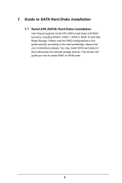
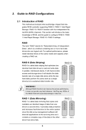
This section will guide you how to create RAID on this guide carefully according to SATA Hard Disks Installation 1.1 Serial ATA (SATA) Hard Disks Installation Intel chipset supports Serial ATA (SATA) hard disks with RAID functions, including RAID 0, RAID 1, RAID 5, RAID 10 and Intel Rapid Storage. 1. Please read the RAID configurations in this motherboard for internal storage devices. Guide to the Intel southbridge chipset that your motherboard adopts. You may install SATA hard disks on SATA ports. 2
This section will guide you how to create RAID on this guide carefully according to SATA Hard Disks Installation 1.1 Serial ATA (SATA) Hard Disks Installation Intel chipset supports Serial ATA (SATA) hard disks with RAID functions, including RAID 0, RAID 1, RAID 5, RAID 10 and Intel Rapid Storage. 1. Please read the RAID configurations in this motherboard for internal storage devices. Guide to the Intel southbridge chipset that your motherboard adopts. You may install SATA hard disks on SATA ports. 2
RAID Installation Guide
Page 3
... introduce the basic knowledge of the same model and capacity when creating a RAID set. This section will double the data transfer rate of RAID This motherboard adopts Intel southbridge chipset that optimizes two identical hard disk drives to configure RAID 0 / RAID 1/ Intel Rapid Storage / RAID 10 / RAID 5 settings. It provides data...
... introduce the basic knowledge of the same model and capacity when creating a RAID set. This section will double the data transfer rate of RAID This motherboard adopts Intel southbridge chipset that optimizes two identical hard disk drives to configure RAID 0 / RAID 1/ Intel Rapid Storage / RAID 10 / RAID 5 settings. It provides data...
RAID Installation Guide
Page 18
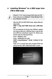
... steps below. STEP 1: Copy Intel® RAID drivers into a USB flash disk You can download the drivers from ASRock's website and unzip the files into a USB flash disk or copy the files from ASRock's motherboard support CD. (Please copy the files under the following directory: 32 bit: ..\i386\Win7_Intel.. 64-bit: ..\AMD64\Win7...
... steps below. STEP 1: Copy Intel® RAID drivers into a USB flash disk You can download the drivers from ASRock's website and unzip the files into a USB flash disk or copy the files from ASRock's motherboard support CD. (Please copy the files under the following directory: 32 bit: ..\i386\Win7_Intel.. 64-bit: ..\AMD64\Win7...
RAID Installation Guide
Page 20
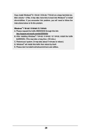
....microsoft.com/kb/2505454/ B. After installing Windows® 7 64-bit / 8 64-bit / 8.1 64-bit, install the hotfix kb2505454. (This may take more time to install motherboard drivers and utilities. 20 Reboot your system. (It may take a long time; >30 mins.) C. If you encounter this problem. Disk volume > 2TB), it may take...
....microsoft.com/kb/2505454/ B. After installing Windows® 7 64-bit / 8 64-bit / 8.1 64-bit, install the hotfix kb2505454. (This may take more time to install motherboard drivers and utilities. 20 Reboot your system. (It may take a long time; >30 mins.) C. If you encounter this problem. Disk volume > 2TB), it may take...

User Manual
Page 2
... merchantability or fitness for informational use only and subject to infringe. CALIFORNIA, USA ONLY The Lithium battery adopted on this motherboard contains Perchlorate, a toxic substance controlled in Perchlorate Best Management Practices (BMP) regulations passed by the purchaser for any defect... conditions: (1) this device may not cause harmful interference, and (2) this documentation may or may be constructed as a commitment by ASRock. Operation is subject to the owners' benefit, without written consent of this documentation are furnished for a particular purpose. Version 1.0 ...
... merchantability or fitness for informational use only and subject to infringe. CALIFORNIA, USA ONLY The Lithium battery adopted on this motherboard contains Perchlorate, a toxic substance controlled in Perchlorate Best Management Practices (BMP) regulations passed by the purchaser for any defect... conditions: (1) this device may not cause harmful interference, and (2) this documentation may or may be constructed as a commitment by ASRock. Operation is subject to the owners' benefit, without written consent of this documentation are furnished for a particular purpose. Version 1.0 ...
User Manual
Page 3
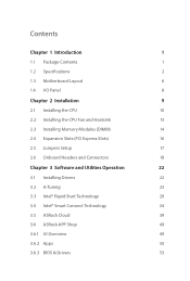
Contents Chapter 1 Introduction 1 1.1 Package Contents 1 1.2 Specifications 2 1.3 Motherboard Layout 6 1.4 I/O Panel 8 Chapter 2 Installation 9 2.1 Installing the CPU 10 2.2 Installing the CPU Fan and Heatsink 13 2.3 Installing Memory Modules (DIMM) 14 2.4 Expansion Slots (PCI Express... Chapter 3 Software and Utilities Operation 22 3.1 Installing Drivers 22 3.2 A-Tuning 23 3.3 Intel® Rapid Start Technology 29 3.4 Intel® Smart Connect Technology 34 3.5 ASRock Cloud 39 3.6 ASRock APP Shop 49 3.6.1 UI Overview 49 3.6.2 Apps 50 3.6.3 BIOS & Drivers 53
Contents Chapter 1 Introduction 1 1.1 Package Contents 1 1.2 Specifications 2 1.3 Motherboard Layout 6 1.4 I/O Panel 8 Chapter 2 Installation 9 2.1 Installing the CPU 10 2.2 Installing the CPU Fan and Heatsink 13 2.3 Installing Memory Modules (DIMM) 14 2.4 Expansion Slots (PCI Express... Chapter 3 Software and Utilities Operation 22 3.1 Installing Drivers 22 3.2 A-Tuning 23 3.3 Intel® Rapid Start Technology 29 3.4 Intel® Smart Connect Technology 34 3.5 ASRock Cloud 39 3.6 ASRock APP Shop 49 3.6.1 UI Overview 49 3.6.2 Apps 50 3.6.3 BIOS & Drivers 53
User Manual
Page 5
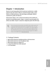
... our website for purchasing ASRock H97M Anniversary motherboard, a reliable motherboard produced under ASRock's consistently stringent quality control. Because the motherboard specifications and the BIOS software might be updated, the content of the motherboard and step-by-step installation guides. ASRock website http://www.asrock.com. 1.1 Package Contents • ASRock H97M Anniversary Motherboard (Micro ATX Form Factor) • ASRock H97M Anniversary Quick Installation Guide • ASRock H97M Anniversary Support CD •...
... our website for purchasing ASRock H97M Anniversary motherboard, a reliable motherboard produced under ASRock's consistently stringent quality control. Because the motherboard specifications and the BIOS software might be updated, the content of the motherboard and step-by-step installation guides. ASRock website http://www.asrock.com. 1.1 Package Contents • ASRock H97M Anniversary Motherboard (Micro ATX Form Factor) • ASRock H97M Anniversary Quick Installation Guide • ASRock H97M Anniversary Support CD •...
User Manual
Page 10
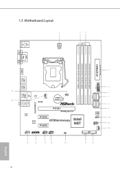
1.3 Motherboard Layout ATX12V1 PS2 Mouse PS2 Keyboard DVI1 VGA1 ATXPWR1 DDR3_A1 (64 bit, 240-pin module) DDR3_A2 (64 bit, 240-pin module) DDR3_B1 (64 bit, 240-... B: USB1 USB 3.0 T: USB0 B: USB1 USB3_2_3 1 USB 2.0 T: USB2 Top: RJ-45 B: USB3 LAN CPU_FAN1 RoHS CMOS Battery 1 CLRCMOS1 Front USB 3.0 PCIE1 PCI Express 3.0 Audio CODEC PCIE2 H97M Anniversary Intel Super I/O H97 PCIE3 HD_AUDIO1 1 1 TPMS1 USB4_5 USB6_7 1 1 CI1 1 SATA_5 64Mb BIOS SPEAKER1 1 PLED PWRBTN 1 HDLED RESET PANEL1 CHA_FAN1 SATA_4 SATA_1 SATA_0 SATA_3 SATA_2 English 6
1.3 Motherboard Layout ATX12V1 PS2 Mouse PS2 Keyboard DVI1 VGA1 ATXPWR1 DDR3_A1 (64 bit, 240-pin module) DDR3_A2 (64 bit, 240-pin module) DDR3_B1 (64 bit, 240-... B: USB1 USB 3.0 T: USB0 B: USB1 USB3_2_3 1 USB 2.0 T: USB2 Top: RJ-45 B: USB3 LAN CPU_FAN1 RoHS CMOS Battery 1 CLRCMOS1 Front USB 3.0 PCIE1 PCI Express 3.0 Audio CODEC PCIE2 H97M Anniversary Intel Super I/O H97 PCIE3 HD_AUDIO1 1 1 TPMS1 USB4_5 USB6_7 1 1 CI1 1 SATA_5 64Mb BIOS SPEAKER1 1 PLED PWRBTN 1 HDLED RESET PANEL1 CHA_FAN1 SATA_4 SATA_1 SATA_0 SATA_3 SATA_2 English 6

User Manual
Page 13
... configuration of the following precautions before installing or removing the motherboard components. Pre-installation Precautions Take note of your motherboard directly on a grounded anti-static pad or in the bag that the motherboard fits into it. H97M Anniversary Chapter 2 Installation This is a Micro ATX form factor motherboard. Also remember to the chassis, please do not touch...
... configuration of the following precautions before installing or removing the motherboard components. Pre-installation Precautions Take note of your motherboard directly on a grounded anti-static pad or in the bag that the motherboard fits into it. H97M Anniversary Chapter 2 Installation This is a Micro ATX form factor motherboard. Also remember to the chassis, please do not touch...
User Manual
Page 16
The cover must be placed if you wish to return the motherboard for after service. 12 English Please save and replace the cover if the processor is removed.
The cover must be placed if you wish to return the motherboard for after service. 12 English Please save and replace the cover if the processor is removed.
User Manual
Page 18
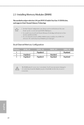
... four 240-pin DDR3 (Double Data Rate 3) DIMM slots, and supports Dual Channel Memory Technology. 1. otherwise, this motherboard and DIMM may be damaged. English 14 It will cause permanent damage to the motherboard and the DIMM if you always need to install identical (the same brand, speed, size and chip-type) DDR3...
... four 240-pin DDR3 (Double Data Rate 3) DIMM slots, and supports Dual Channel Memory Technology. 1. otherwise, this motherboard and DIMM may be damaged. English 14 It will cause permanent damage to the motherboard and the DIMM if you always need to install identical (the same brand, speed, size and chip-type) DDR3...
User Manual
Page 20
... Express slots on PCIE1 slot, please find a thin tool, such as a pen to press the retaining clip to install/uninstall the graphics card on the motherboard. 1. Due to the mechanical limitation, to lock/unlock the PCIe slot. Before installing an expansion card, please make necessary hardware settings for PCI Express x1...
... Express slots on PCIE1 slot, please find a thin tool, such as a pen to press the retaining clip to install/uninstall the graphics card on the motherboard. 1. Due to the mechanical limitation, to lock/unlock the PCIe slot. Before installing an expansion card, please make necessary hardware settings for PCI Express x1...
User Manual
Page 22
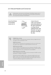
... restart the computer if the computer freezes and fails to the reset switch on the chassis front panel. PLED (System Power LED): Connect to the motherboard. The front panel design may configure the way to turn off (S5). 2.6 Onboard Headers and Connectors Onboard headers and connectors are matched correctly. Do NOT...
... restart the computer if the computer freezes and fails to the reset switch on the chassis front panel. PLED (System Power LED): Connect to the motherboard. The front panel design may configure the way to turn off (S5). 2.6 Onboard Headers and Connectors Onboard headers and connectors are matched correctly. Do NOT...
User Manual
Page 23
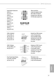
.... Front Panel Audio Header (9-pin HD_AUDIO1) (see p.6, No. 19) GND PRESENCE# MIC_RET OUT_RET 1 OUT2_L J_SENSE OUT2_R MIC2_R MIC2_L This header is one header on this motherboard. H97M Anniversary Serial ATA3 Connectors (SATA_0: see p.6, No. 7) (SATA_1: see p.6, No. 6) (SATA_2: see p.6, No. 8) (SATA_3: see p.6, No. 9) (SATA_4: see p.6, No. 13) (SATA_5: see p.6, No. ...+ GND IntA_PA_DIntA_PA_D+ Vbus IntA_PB_SSRXIntA_PB_SSRX+ GND IntA_PB_SSTXIntA_PB_SSTX+ GND IntA_PB_DIntA_PB_D+ Dummy 1 Besides two USB 3.0 ports on the I /O panel, there are two headers on this motherboard.
.... Front Panel Audio Header (9-pin HD_AUDIO1) (see p.6, No. 19) GND PRESENCE# MIC_RET OUT_RET 1 OUT2_L J_SENSE OUT2_R MIC2_R MIC2_L This header is one header on this motherboard. H97M Anniversary Serial ATA3 Connectors (SATA_0: see p.6, No. 7) (SATA_1: see p.6, No. 6) (SATA_2: see p.6, No. 8) (SATA_3: see p.6, No. 9) (SATA_4: see p.6, No. 13) (SATA_5: see p.6, No. ...+ GND IntA_PA_DIntA_PA_D+ Vbus IntA_PB_SSRXIntA_PB_SSRX+ GND IntA_PB_SSTXIntA_PB_SSTX+ GND IntA_PB_DIntA_PB_D+ Dummy 1 Besides two USB 3.0 ports on the I /O panel, there are two headers on this motherboard.
User Manual
Page 24
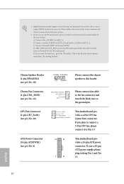
... audio panel. To activate the front mic, go to Pin 1-3. ATX Power Connector (24-pin ATXPWR1) (see p.6, No. 20) 1 GND This motherboard pro- 2 +12V 3 FAN_SPEED vides a 4-Pin CPU fan 4 FAN_SPEED_CONTROL (Quiet Fan) connector. D. CPU Fan Connector (4-pin CPU_FAN1) (see p.6, No. 4) 12 ...24 1 13 This motherboard provides a 24-pin ATX power connector. 1. If you use a 20-pin ATX power supply, please plug it to the "FrontMic" Tab in our ...
... audio panel. To activate the front mic, go to Pin 1-3. ATX Power Connector (24-pin ATXPWR1) (see p.6, No. 20) 1 GND This motherboard pro- 2 +12V 3 FAN_SPEED vides a 4-Pin CPU fan 4 FAN_SPEED_CONTROL (Quiet Fan) connector. D. CPU Fan Connector (4-pin CPU_FAN1) (see p.6, No. 4) 12 ...24 1 13 This motherboard provides a 24-pin ATX power connector. 1. If you use a 20-pin ATX power supply, please plug it to the "FrontMic" Tab in our ...
User Manual
Page 25
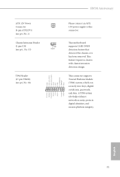
..., digital certificates, passwords, and data. This motherboard supports CASE OPEN detection feature that detects if the chassis cove has been removed. A TPM system also helps enhance network security, protects digital identities, and ensures platform integrity. This feature requires a chassis with chassis intrusion detection design. H97M Anniversary ATX 12V Power Connector (4-pin ATX12V1) (see...
..., digital certificates, passwords, and data. This motherboard supports CASE OPEN detection feature that detects if the chassis cove has been removed. A TPM system also helps enhance network security, protects digital identities, and ensures platform integrity. This feature requires a chassis with chassis intrusion detection design. H97M Anniversary ATX 12V Power Connector (4-pin ATX12V1) (see...
User Manual
Page 26
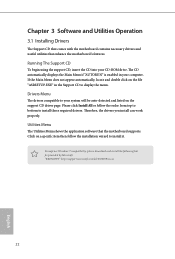
... the menu. "KB2720599": http://support.microsoft.com/kb/2720599/en-us 22 English Utilities Menu The Utilities Menu shows the application software that enhance the motherboard's features. Therefore, the drivers you install can work properly. Please click Install All or follow the installation wizard to install those required drivers. To ...automatically, locate and double click on the support CD driver page. Chapter 3 Software and Utilities Operation 3.1 Installing Drivers The Support CD that comes with the motherboard contains necessary drivers and useful utilities that the...
... the menu. "KB2720599": http://support.microsoft.com/kb/2720599/en-us 22 English Utilities Menu The Utilities Menu shows the application software that enhance the motherboard's features. Therefore, the drivers you install can work properly. Please click Install All or follow the installation wizard to install those required drivers. To ...automatically, locate and double click on the support CD driver page. Chapter 3 Software and Utilities Operation 3.1 Installing Drivers The Support CD that comes with the motherboard contains necessary drivers and useful utilities that the...
User Manual
Page 29
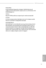
... on , and the duration of the dehumidifying process. Enable this OC setting profile to save your computer log in red color). values, current temperature, etc. H97M Anniversary Dehumidifier Prevent motherboard damages due to windows automatically! Click on the health status icon to configure settings for an alert to be triggered. 25 English
... on , and the duration of the dehumidifying process. Enable this OC setting profile to save your computer log in red color). values, current temperature, etc. H97M Anniversary Dehumidifier Prevent motherboard damages due to windows automatically! Click on the health status icon to configure settings for an alert to be triggered. 25 English

