
User Manual
Page 3
...Motherboard Layout 12 1.4 I/O Panel 13 2 Installation 14 2.1 Screw Holes 14 2.2 Pre-installation Precautions 14 2.3 CPU Installation 15 2.4 Installation of Heatsink and CPU fan 17 2.5 Installation of Memory Modules (DIMM 18 2.6 Expansion Slots (PCI Express Slots 19 2.7 Dual Monitor and Surround Display Features 20 2.8 Jumpers Setup 23 2.9 Onboard Headers and Connectors 24 2.10 Serial ATA (SATA) / Serial ATAII (SATAII) Hard Disks Installation 28 2.11 Hot Plug Function for SATA / SATAII HDDs 28 2.12 SATA / SATAII HDD Hot Plug Feature and Operation Guide 29 2.13 Driver Installation...
...Motherboard Layout 12 1.4 I/O Panel 13 2 Installation 14 2.1 Screw Holes 14 2.2 Pre-installation Precautions 14 2.3 CPU Installation 15 2.4 Installation of Heatsink and CPU fan 17 2.5 Installation of Memory Modules (DIMM 18 2.6 Expansion Slots (PCI Express Slots 19 2.7 Dual Monitor and Surround Display Features 20 2.8 Jumpers Setup 23 2.9 Onboard Headers and Connectors 24 2.10 Serial ATA (SATA) / Serial ATAII (SATAII) Hard Disks Installation 28 2.11 Hot Plug Function for SATA / SATAII HDDs 28 2.12 SATA / SATAII HDD Hot Plug Feature and Operation Guide 29 2.13 Driver Installation...

User Manual
Page 6
...; Extreme Memory Profile (XMP) 1.3 / 1.2 with Intel® Ivy Bridge CPU - 1 x PCI Express 3.0 x16 slot (blue @ x16 mode) * PCIE 3.0 is only supported with Intel® Sandy Bridge CPU) - Max. Micro ATX Form Factor: 8.9-in x 6.8-in Visuals: Intel® Quick Sync Video 2.0, Intel® InTruTM 3D, Intel® Clear Video HD Technology, Intel® InsiderTM, Intel® HD Graphics 2500/4000 with Intel® Ivy Bridge CPU - Dual Channel DDR3 Memory Technology...
...; Extreme Memory Profile (XMP) 1.3 / 1.2 with Intel® Ivy Bridge CPU - 1 x PCI Express 3.0 x16 slot (blue @ x16 mode) * PCIE 3.0 is only supported with Intel® Sandy Bridge CPU) - Max. Micro ATX Form Factor: 8.9-in x 6.8-in Visuals: Intel® Quick Sync Video 2.0, Intel® InTruTM 3D, Intel® Clear Video HD Technology, Intel® InsiderTM, Intel® HD Graphics 2500/4000 with Intel® Ivy Bridge CPU - Dual Channel DDR3 Memory Technology...

User Manual
Page 9
... press key to BIOS setup menu to utilize the memory that the USB flash drive or hard drive must use . 4. You can update your system. In Hardware Monitor, it shows the fan speed and temperature for optimal system performance. Please visit our website for proper installation. 3. About the setting of your BIOS only in Flash ROM. The maximum shared memory size is defined by the chipset vendor and is including Hardware Monitor, Fan Control, Overclocking...
... press key to BIOS setup menu to utilize the memory that the USB flash drive or hard drive must use . 4. You can update your system. In Hardware Monitor, it shows the fan speed and temperature for optimal system performance. Please visit our website for proper installation. 3. About the setting of your BIOS only in Flash ROM. The maximum shared memory size is defined by the chipset vendor and is including Hardware Monitor, Fan Control, Overclocking...

User Manual
Page 10
... video and download files simultaneously. The performance may depend on the motherboard functions properly and unplug the power cord, then plug it can configure your real-time newsfeed into Standby mode (S1), Suspend to RAM (S3), hibernation mode (S4) or power off (S5). ASRock XFast LAN provides a faster internet access, which data streams you - It also shortens the loading time of the device. 10. ASRock...
... video and download files simultaneously. The performance may depend on the motherboard functions properly and unplug the power cord, then plug it can configure your real-time newsfeed into Standby mode (S1), Suspend to RAM (S3), hibernation mode (S4) or power off (S5). ASRock XFast LAN provides a faster internet access, which data streams you - It also shortens the loading time of the device. 10. ASRock...

User Manual
Page 12
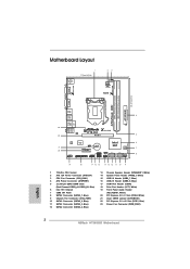
...) 13 Chassis Speaker Header (SPEAKER 1, White) 14 System Panel Header (PANEL1, White) 15 USB 2.0 Header (USB6_7, Blue) 16 USB 2.0 Header (USB8_9, Blue) 17 COM Port Header (COM1) 18 Print Port Header (LPT1, White) 19 Front Panel Audio Header (HD_AUDIO1, White) 20 PCI Express 2.0 x1 Slot (PCIE2, White) 21 Clear CMOS Jumper (CLRCMOS1) 22 PCI Express 3.0 x16 Slot (PCIE1, Blue) 23 Power Fan Connector (PWR_FAN1) 12 D G 3 PWR_FAN1 LAN PHY 5 22 PCIE1 Designed in ) DDR3_B1 (64 bit, 240-pin module) DDR3_A1 (64 bit, 240-pin module...
...) 13 Chassis Speaker Header (SPEAKER 1, White) 14 System Panel Header (PANEL1, White) 15 USB 2.0 Header (USB6_7, Blue) 16 USB 2.0 Header (USB8_9, Blue) 17 COM Port Header (COM1) 18 Print Port Header (LPT1, White) 19 Front Panel Audio Header (HD_AUDIO1, White) 20 PCI Express 2.0 x1 Slot (PCIE2, White) 21 Clear CMOS Jumper (CLRCMOS1) 22 PCI Express 3.0 x16 Slot (PCIE1, Blue) 23 Power Fan Connector (PWR_FAN1) 12 D G 3 PWR_FAN1 LAN PHY 5 22 PCIE1 Designed in ) DDR3_B1 (64 bit, 240-pin module) DDR3_A1 (64 bit, 240-pin module...

User Manual
Page 20
... the benefits of dual monitor feature without installing any add-on the I /O panel, and connect D-Sub monitor cable to D-Sub port on VGA card to DVI-D port on the I /O panel. D-Sub port DVI-D port 2. To enable dual monitor feature, please follow the below steps: 1. If you can drive same or different display contents. Connect DVI-D monitor cable to this motherboard. If you have installed onboard VGA driver from our support CD to support dual VGA output so that DVI...
... the benefits of dual monitor feature without installing any add-on the I /O panel, and connect D-Sub monitor cable to D-Sub port on VGA card to DVI-D port on the I /O panel. D-Sub port DVI-D port 2. To enable dual monitor feature, please follow the below steps: 1. If you can drive same or different display contents. Connect DVI-D monitor cable to this motherboard. If you have installed onboard VGA driver from our support CD to support dual VGA output so that DVI...

User Manual
Page 21
... card installation procedures for the diaplay icon identified by the number 2. Then connect other monitor cables to D-Sub port on each monitor. Click the "Identify" button to display a large number on the I /O panel, and connect D-Sub monitor cable to the corresponding connectors of "Onboard VGA Share Memory", [Auto], will be your system. Set the "Screen Resolution" and "Color Quality" as Secondary. Surround Display Feature This motherboard supports surround display upgrade. C. F. Set up a surround display environment: 1. Connect...
... card installation procedures for the diaplay icon identified by the number 2. Then connect other monitor cables to D-Sub port on each monitor. Click the "Identify" button to display a large number on the I /O panel, and connect D-Sub monitor cable to the corresponding connectors of "Onboard VGA Share Memory", [Auto], will be your system. Set the "Screen Resolution" and "Color Quality" as Secondary. Surround Display Feature This motherboard supports surround display upgrade. C. F. Set up a surround display environment: 1. Connect...

User Manual
Page 31
... drivers you install can be auto-detected and listed on your SATA / SATAII HDDs without RAID functions, please follow the order from up , press key, and then a window for boot devices selection appears. Using SATA / SATAII HDDs with NCQ function STEP 1: Set Up UEFI. B. Set the option "SATA Mode Selection" to format the floppy diskette and copy SATA / SATAII drivers into your optical drive to your system can work properly. 2.14 Installing Windows® 7 / 7 64-bit...
... drivers you install can be auto-detected and listed on your SATA / SATAII HDDs without RAID functions, please follow the order from up , press key, and then a window for boot devices selection appears. Using SATA / SATAII HDDs with NCQ function STEP 1: Set Up UEFI. B. Set the option "SATA Mode Selection" to format the floppy diskette and copy SATA / SATAII drivers into your optical drive to your system can work properly. 2.14 Installing Windows® 7 / 7 64-bit...

User Manual
Page 40
The default value is [All]. Set to OS. Active Processor Cores Use this to enable or disable CPU C6 (ACPI C3) report to keep the CPU from the chipset. Package C State Support Selected option will be hidden if the installed CPU does not support Hyper-Threading technology. CPU Thermal Throttling You may select [Enabled] to enable CPU internal thermal control mechanism to OS. The default value is [Auto]. In the C1 power state, the processor maintains the context...
The default value is [All]. Set to OS. Active Processor Cores Use this to enable or disable CPU C6 (ACPI C3) report to keep the CPU from the chipset. Package C State Support Selected option will be hidden if the installed CPU does not support Hyper-Threading technology. CPU Thermal Throttling You may select [Enabled] to enable CPU internal thermal control mechanism to OS. The default value is [Auto]. In the C1 power state, the processor maintains the context...

User Manual
Page 49
... Use this item to enable or disable the use only under legacy OS and UEFI setup when [Disabled] is [Enabled]. Please refer to select legacy support for legacy USB. [Auto] - If you have USB compatibility issues, it is recommended to select [Disabled] to enter OS. [UEFI Setup Only] - Enables support for USB devices. 3.4.9 USB Configuration USB 2.0 Controller Use this option to below descriptions for the details of USB 2.0 controller. Enables legacy support if USB devices are four configuration options: [Enabled], [Auto], [Disabled] and [UEFI Setup Only]. There are connected...
... Use this item to enable or disable the use only under legacy OS and UEFI setup when [Disabled] is [Enabled]. Please refer to select legacy support for legacy USB. [Auto] - If you have USB compatibility issues, it is recommended to select [Disabled] to enter OS. [UEFI Setup Only] - Enables support for USB devices. 3.4.9 USB Configuration USB 2.0 Controller Use this option to below descriptions for the details of USB 2.0 controller. Enables legacy support if USB devices are four configuration options: [Enabled], [Auto], [Disabled] and [UEFI Setup Only]. There are connected...

User Manual
Page 54
... devices. 4.2.3 Utilities Menu The Utilities Menu shows the applications software that enhance the motherboard features. 4.2.1 Running The Support CD To begin using the support CD, insert the CD into your computer. Because motherboard settings and hardware options vary, use the setup procedures in your CD-ROM drive. Please install the necessary drivers to know more information. 4.2 Support CD Information The Support CD that came with the motherboard contains necessary drivers and useful utilities that the motherboard supports...
... devices. 4.2.3 Utilities Menu The Utilities Menu shows the applications software that enhance the motherboard features. 4.2.1 Running The Support CD To begin using the support CD, insert the CD into your computer. Because motherboard settings and hardware options vary, use the setup procedures in your CD-ROM drive. Please install the necessary drivers to know more information. 4.2 Support CD Information The Support CD that came with the motherboard contains necessary drivers and useful utilities that the motherboard supports...
Quick Installation Guide
Page 2
...) 13 Chassis Speaker Header (SPEAKER 1, White) 14 System Panel Header (PANEL1, White) 15 USB 2.0 Header (USB6_7, Blue) 16 USB 2.0 Header (USB8_9, Blue) 17 COM Port Header (COM1) 18 Print Port Header (LPT1, White) 19 Front Panel Audio Header (HD_AUDIO1, White) 20 PCI Express 2.0 x1 Slot (PCIE2, White) 21 Clear CMOS Jumper (CLRCMOS1) 22 PCI Express 3.0 x16 Slot (PCIE1, Blue) 23 Power Fan Connector (PWR_FAN1) 2 ASRock H71M-DG3 Motherboard English D G 3 PWR_FAN1 LAN PHY 5 22 PCIE1 Designed in ) DDR3_B1 (64 bit, 240-pin module) DDR3_A1 (64 bit, 240-pin module...
...) 13 Chassis Speaker Header (SPEAKER 1, White) 14 System Panel Header (PANEL1, White) 15 USB 2.0 Header (USB6_7, Blue) 16 USB 2.0 Header (USB8_9, Blue) 17 COM Port Header (COM1) 18 Print Port Header (LPT1, White) 19 Front Panel Audio Header (HD_AUDIO1, White) 20 PCI Express 2.0 x1 Slot (PCIE2, White) 21 Clear CMOS Jumper (CLRCMOS1) 22 PCI Express 3.0 x16 Slot (PCIE1, Blue) 23 Power Fan Connector (PWR_FAN1) 2 ASRock H71M-DG3 Motherboard English D G 3 PWR_FAN1 LAN PHY 5 22 PCIE1 Designed in ) DDR3_B1 (64 bit, 240-pin module) DDR3_A1 (64 bit, 240-pin module...

Quick Installation Guide
Page 4
... website for purchasing ASRock H71M-DG3 motherboard, a reliable motherboard produced under ASRock's consistently stringent quality control. To get better performance in Windows® 7 / 7 64-bit / VistaTM / VistaTM 64bit, it is recommended to set the BIOS option in , 22.6 cm x 17.3 cm) ASRock H71M-DG3 Quick Installation Guide ASRock H71M-DG3 Support CD 2 x Serial ATA (SATA) Data Cables (Optional) 1 x I/O Panel Shield ASRock Reminds You... ASRock website http://www.asrock.com If you for specific information about the model you are using.
... website for purchasing ASRock H71M-DG3 motherboard, a reliable motherboard produced under ASRock's consistently stringent quality control. To get better performance in Windows® 7 / 7 64-bit / VistaTM / VistaTM 64bit, it is recommended to set the BIOS option in , 22.6 cm x 17.3 cm) ASRock H71M-DG3 Quick Installation Guide ASRock H71M-DG3 Support CD 2 x Serial ATA (SATA) Data Cables (Optional) 1 x I/O Panel Shield ASRock Reminds You... ASRock website http://www.asrock.com If you for specific information about the model you are using.
Quick Installation Guide
Page 5
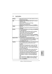
... Smart Connect Technology - capacity of system memory: 16GB (see CAUTION 1) - Max. Max. shared memory 1759MB with Intel® Sandy Bridge CPU. (see CAUTION 2) - 2 x DDR3 DIMM slots - 1.2 Specifications Platform CPU Chipset Memory Expansion Slot Graphics - Pixel Shader 5.0, DirectX 11 with Intel® Ivy Bridge CPU. shared memory 1760MB with Intel® Ivy Bridge CPU. Supports K-Series unlocked CPU - Supports Intel® Extreme Memory Profile (XMP) 1.3 / 1.2 with Intel® Ivy Bridge CPU - 1 x PCI Express 3.0 x16 slot (blue @ x16 mode) * PCIE...
... Smart Connect Technology - capacity of system memory: 16GB (see CAUTION 1) - Max. Max. shared memory 1759MB with Intel® Sandy Bridge CPU. (see CAUTION 2) - 2 x DDR3 DIMM slots - 1.2 Specifications Platform CPU Chipset Memory Expansion Slot Graphics - Pixel Shader 5.0, DirectX 11 with Intel® Ivy Bridge CPU. shared memory 1760MB with Intel® Ivy Bridge CPU. Supports K-Series unlocked CPU - Supports Intel® Extreme Memory Profile (XMP) 1.3 / 1.2 with Intel® Ivy Bridge CPU - 1 x PCI Express 3.0 x16 slot (blue @ x16 mode) * PCIE...
Quick Installation Guide
Page 8
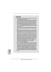
... for the operation procedures of "User Manual" in Flash ROM. CAUTION! 1. About the setting of "Hyper Threading Technology", please check page 40 of ASRock Extreme Tuning Utility (AXTU). For Windows® OS with your USB flash drive, floppy disk or hard drive, then you to utilize the memory that the USB flash drive or hard drive must use . 4. ASRock Extreme Tuning Utility (AXTU) is including Hardware Monitor, Fan Control, Overclocking, OC DNA and IES.
... for the operation procedures of "User Manual" in Flash ROM. CAUTION! 1. About the setting of "Hyper Threading Technology", please check page 40 of ASRock Extreme Tuning Utility (AXTU). For Windows® OS with your USB flash drive, floppy disk or hard drive, then you to utilize the memory that the USB flash drive or hard drive must use . 4. ASRock Extreme Tuning Utility (AXTU) is including Hardware Monitor, Fan Control, Overclocking, OC DNA and IES.

Quick Installation Guide
Page 9
... boost USB storage device performance. Before you to RAM (S3), hibernation mode (S4) or power off (S5). Please be noticed that not all the 775 and 1156 CPU Fan can lower the latency in Game: After setting online game priority higher, it reduces the frequency of ASRock XFast RAM is the smart start page for IE that cannot be used under Windows® OS 32-bit CPU. Simply installing...
... boost USB storage device performance. Before you to RAM (S3), hibernation mode (S4) or power off (S5). Please be noticed that not all the 775 and 1156 CPU Fan can lower the latency in Game: After setting online game priority higher, it reduces the frequency of ASRock XFast RAM is the smart start page for IE that cannot be used under Windows® OS 32-bit CPU. Simply installing...

Quick Installation Guide
Page 16
...-D port 2. Connect DVI-D monitor cable to DVI-D port on the I/O panel, and connect D-Sub monitor cable to D-Sub port on VGA card to your system and restart your system already, you can drive same or different display contents. English 16 ASRock H71M-DG3 Motherboard With the internal VGA output support (DVI-D and D-Sub), you can freely enjoy the benefits of dual monitor feature without installing any add-on the I/O panel. If you have installed onboard VGA driver...
...-D port 2. Connect DVI-D monitor cable to DVI-D port on the I/O panel, and connect D-Sub monitor cable to D-Sub port on VGA card to your system and restart your system already, you can drive same or different display contents. English 16 ASRock H71M-DG3 Motherboard With the internal VGA output support (DVI-D and D-Sub), you can freely enjoy the benefits of dual monitor feature without installing any add-on the I/O panel. If you have installed onboard VGA driver...

Quick Installation Guide
Page 17
.... Surround Display Feature This motherboard supports surround display upgrade. If you can adjust the parameters of the system memory. A. Connect DVI-D monitor cable to DVI-D port on VGA card is less than the total capability of the multi-monitor according to set up a multi-monitor display. Click "Extend my Windows desktop onto this motherboard. 4. With the internal VGA output support (DVI-D and D-Sub) and external add-on PCI Express VGA cards, you have installed the drivers already, there...
.... Surround Display Feature This motherboard supports surround display upgrade. If you can adjust the parameters of the system memory. A. Connect DVI-D monitor cable to DVI-D port on VGA card is less than the total capability of the multi-monitor according to set up a multi-monitor display. Click "Extend my Windows desktop onto this motherboard. 4. With the internal VGA output support (DVI-D and D-Sub) and external add-on PCI Express VGA cards, you have installed the drivers already, there...

Quick Installation Guide
Page 24
... support CD to your system. 24 ASRock H71M-DG3 Motherboard English Enter UEFI SETUP UTILITY Advanced screen Storage Configuration. STEP 2: Install Windows® XP / XP 64-bit OS on your system. 2.9.2 Installing Windows® 7 / 7 64-bit / VistaTM / VistaTM 64-bit Without RAID Functions If you want to install Windows® 7 / 7 64-bit / VistaTM / VistaTM 64-bit OS on your SATA / SATAII HDDs without RAID functions, please follow below steps. Using SATA / SATAII HDDs without NCQ function STEP 1: Set...
... support CD to your system. 24 ASRock H71M-DG3 Motherboard English Enter UEFI SETUP UTILITY Advanced screen Storage Configuration. STEP 2: Install Windows® XP / XP 64-bit OS on your system. 2.9.2 Installing Windows® 7 / 7 64-bit / VistaTM / VistaTM 64-bit Without RAID Functions If you want to install Windows® 7 / 7 64-bit / VistaTM / VistaTM 64-bit OS on your SATA / SATAII HDDs without RAID functions, please follow below steps. Using SATA / SATAII HDDs without NCQ function STEP 1: Set...
Quick Installation Guide
Page 25
A. otherwise, POST continues with the motherboard contains necessary drivers and useful utilities that came with its various sub-menus and to the User Manual (PDF file) contained in the Support CD. 4. If the Main Menu does not appear automatically, locate and double-click on the motherboard stores BIOS Setup Utility. B. Set the option "SATA Mode Selection" to enter BIOS Setup utility; If you wish to display the menus. 25 ASRock H71M-DG3 Motherboard English It is designed to scroll...
A. otherwise, POST continues with the motherboard contains necessary drivers and useful utilities that came with its various sub-menus and to the User Manual (PDF file) contained in the Support CD. 4. If the Main Menu does not appear automatically, locate and double-click on the motherboard stores BIOS Setup Utility. B. Set the option "SATA Mode Selection" to enter BIOS Setup utility; If you wish to display the menus. 25 ASRock H71M-DG3 Motherboard English It is designed to scroll...


