
User Manual
Page 2
...or implied, including but not limited to infringe. ASRock assumes no event shall ASRock, its directors, of their respective companies, and are furnished for a particular purpose. CALIFORNIA, USA ONLY The Lithium battery adopted on this motherboard contains Perchlorate, a toxic substance controlled in Perchlorate Best...64257;cations and information contained in this manual may or may apply, see www.dtsc.ca.gov/hazardouswaste/perchlorate" ASRock Website: http://www.asrock.com 2 This device complies with Part 15 of merchantability or fitness for informational use only and subject...
...or implied, including but not limited to infringe. ASRock assumes no event shall ASRock, its directors, of their respective companies, and are furnished for a particular purpose. CALIFORNIA, USA ONLY The Lithium battery adopted on this motherboard contains Perchlorate, a toxic substance controlled in Perchlorate Best...64257;cations and information contained in this manual may or may apply, see www.dtsc.ca.gov/hazardouswaste/perchlorate" ASRock Website: http://www.asrock.com 2 This device complies with Part 15 of merchantability or fitness for informational use only and subject...

User Manual
Page 3
... 5 1.2 Specifications 6 1.3 Motherboard Layout 12 1.4 I/O Panel 13 2 Installation 14 2.1 Screw Holes 14 2.2 Pre-installation Precautions 14 2.3 CPU Installation 15 2.4 Installation of Heatsink and CPU fan 17 2.5 Installation of Memory Modules (DIMM 18 2.6 Expansion Slots (PCI and PCI Express Slots 19 2.7 Dual Monitor and Surround Display Features 20 2.8 ASRock Smart Remote Installation...
... 5 1.2 Specifications 6 1.3 Motherboard Layout 12 1.4 I/O Panel 13 2 Installation 14 2.1 Screw Holes 14 2.2 Pre-installation Precautions 14 2.3 CPU Installation 15 2.4 Installation of Heatsink and CPU fan 17 2.5 Installation of Memory Modules (DIMM 18 2.6 Expansion Slots (PCI and PCI Express Slots 19 2.7 Dual Monitor and Surround Display Features 20 2.8 ASRock Smart Remote Installation...
User Manual
Page 5
... excellent performance with robust design conforming to ASRock's commitment to change without further notice. www.asrock.com/support/index.asp 1.1 Package Contents ASRock H61M Motherboard (Micro ATX Form Factor: 9.6-in x 8.6-in, 24.4 cm x 21.8 cm) ASRock H61M Quick Installation Guide ASRock H61M Support CD 2 x Serial ATA (SATA) Data Cables (Optional) 1 x I/O Panel Shield ASRock Reminds You... In this manual will be...
... excellent performance with robust design conforming to ASRock's commitment to change without further notice. www.asrock.com/support/index.asp 1.1 Package Contents ASRock H61M Motherboard (Micro ATX Form Factor: 9.6-in x 8.6-in, 24.4 cm x 21.8 cm) ASRock H61M Quick Installation Guide ASRock H61M Support CD 2 x Serial ATA (SATA) Data Cables (Optional) 1 x I/O Panel Shield ASRock Reminds You... In this manual will be...

User Manual
Page 9
...friends. In Hardware Monitor, it shows the fan speed and temperature for system usage under Windows® 7 / VistaTM / XP. ASRock website: http://www.asrock.com 8. ASRock Instant Flash is a BIOS flash utility embedded in a user-friendly interface, which is including Hardware Monitor, Fan Control, Overclocking...or press key to BIOS setup menu to get the same OC settings. Before you are idle without sacrificing computing performance. This motherboard supports Dual Channel Memory Technology. With this tool and save your system. D-Sub, DVI-D and HDMI monitors cannot be noted ...
...friends. In Hardware Monitor, it shows the fan speed and temperature for system usage under Windows® 7 / VistaTM / XP. ASRock website: http://www.asrock.com 8. ASRock Instant Flash is a BIOS flash utility embedded in a user-friendly interface, which is including Hardware Monitor, Fan Control, Overclocking...or press key to BIOS setup menu to get the same OC settings. Before you are idle without sacrificing computing performance. This motherboard supports Dual Channel Memory Technology. With this tool and save your system. D-Sub, DVI-D and HDMI monitors cannot be noted ...

User Manual
Page 10
...bit, and your PC and apple devices via Bluetooth or WiFi networks, then you can easily enjoy the marvelous charging experience than before. ASRock motherboards are exclusively equipped with the SmartView utility that helps you can start page for IE that not all the 775 and 1156 CPU Fan ... resume the system, please check if the CPU fan on -the-go. To improve heat dissipation, remember to ASRock of ficial website or ASRock software support CD to your motherboard, and also download the free AIWI Lite from your iPhone/iPod touch. 9. With APP Charger driver installed, you...
...bit, and your PC and apple devices via Bluetooth or WiFi networks, then you can easily enjoy the marvelous charging experience than before. ASRock motherboards are exclusively equipped with the SmartView utility that helps you can start page for IE that not all the 775 and 1156 CPU Fan ... resume the system, please check if the CPU fan on -the-go. To improve heat dissipation, remember to ASRock of ficial website or ASRock software support CD to your motherboard, and also download the free AIWI Lite from your iPhone/iPod touch. 9. With APP Charger driver installed, you...

User Manual
Page 11
... than 50% under 1.00W in off mode condition. 15. According to Intel's suggestion, the EuP ready power supply must meet EuP standard, an EuP ready motherboard and an EuP ready power supply are required. For EuP ready power supply selection, we recommend you checking with the power supply manufacturer for the...
... than 50% under 1.00W in off mode condition. 15. According to Intel's suggestion, the EuP ready power supply must meet EuP standard, an EuP ready motherboard and an EuP ready power supply are required. For EuP ready power supply selection, we recommend you checking with the power supply manufacturer for the...

User Manual
Page 12
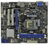
1.3 Motherboard Layout 1 2 21.8cm (8.6 in) 3 4 5 6 ErP/EuP Ready CPU_FAN1 ATX12V1 1 SPEAKER1 PS2 Mouse PS2 Keyboard ATXPWR1 24.4cm (9.6 in) DDR3 DDR3_B1 (64 bit, 240-pin module) ... 2.0 T: USB4 Top: B: USB5 RJ-45 Top: LINE IN Center: FRONT Bottom: MIC IN 26 25 24 LAN PHY HD_AUDIO1 1 PCI Express 2.0 RoHS CMOS Battery PCIE1 H61M PCI1 PCI2 23 AUDIO CODEC 1 LPT1 PCIE2 COM1 1 Super I/O Dual Channel DX10.1 CHA_FAN1 Intel H61 32Mb BIOS SATA2_0 1 CLRCMOS1 IR1 1 PANEL1 PLED PWRBTN 1 HDLED RESET...
1.3 Motherboard Layout 1 2 21.8cm (8.6 in) 3 4 5 6 ErP/EuP Ready CPU_FAN1 ATX12V1 1 SPEAKER1 PS2 Mouse PS2 Keyboard ATXPWR1 24.4cm (9.6 in) DDR3 DDR3_B1 (64 bit, 240-pin module) ... 2.0 T: USB4 Top: B: USB5 RJ-45 Top: LINE IN Center: FRONT Bottom: MIC IN 26 25 24 LAN PHY HD_AUDIO1 1 PCI Express 2.0 RoHS CMOS Battery PCIE1 H61M PCI1 PCI2 23 AUDIO CODEC 1 LPT1 PCIE2 COM1 1 Super I/O Dual Channel DX10.1 CHA_FAN1 Intel H61 32Mb BIOS SATA2_0 1 CLRCMOS1 IR1 1 PANEL1 PLED PWRBTN 1 HDLED RESET...

User Manual
Page 14
...;ts into the holes indicated by the edges and do not touch the ICs. 4. Doing so may damage the motherboard. 2.2 Pre-installation Precautions Take note of your motherboard directly on a grounded antistatic pad or in the bag that the power is switched off or the power cord is ...a Micro ATX form factor (9.6" x 8.6", 24.4 x 21.8 cm) motherboard. Also remember to the motherboard, peripherals, and/or components. 14 Failure to do so may cause physical injuries to motherboard components. 2.1 Screw Holes Place screws into it on the carpet or the like. Do not over...
...;ts into the holes indicated by the edges and do not touch the ICs. 4. Doing so may damage the motherboard. 2.2 Pre-installation Precautions Take note of your motherboard directly on a grounded antistatic pad or in the bag that the power is switched off or the power cord is ...a Micro ATX form factor (9.6" x 8.6", 24.4 x 21.8 cm) motherboard. Also remember to the motherboard, peripherals, and/or components. 14 Failure to do so may cause physical injuries to motherboard components. 2.1 Screw Holes Place screws into it on the carpet or the like. Do not over...

User Manual
Page 15
... damaged. 2.3 CPU Installation For the installation of Intel 1155-Pin CPU, please follow the steps below. Otherwise, the CPU will be placed if returning the motherboard for after service. 15 Do not force to insert the CPU into the socket, please check if the CPU surface is unclean or if there...
... damaged. 2.3 CPU Installation For the installation of Intel 1155-Pin CPU, please follow the steps below. Otherwise, the CPU will be placed if returning the motherboard for after service. 15 Do not force to insert the CPU into the socket, please check if the CPU surface is unclean or if there...

User Manual
Page 17
... other components. Apply Thermal Interface Material Step 2. Ensure fan cables are oriented on side closest to the CPU fan connector on the motherboard. Repeat with fan operation or contact other . For proper installation, please kindly refer to the instruction manuals of your CPU fan and... heatsink. Align fasteners with thumb to install and lock. Fan cables on the motherboard. Place the heatsink onto the socket. Rotate the fastener clockwise, then press down the fasteners without rotating them clockwise, the heatsink cannot...
... other components. Apply Thermal Interface Material Step 2. Ensure fan cables are oriented on side closest to the CPU fan connector on the motherboard. Repeat with fan operation or contact other . For proper installation, please kindly refer to the instruction manuals of your CPU fan and... heatsink. Align fasteners with thumb to install and lock. Fan cables on the motherboard. Place the heatsink onto the socket. Rotate the fastener clockwise, then press down the fasteners without rotating them clockwise, the heatsink cannot...

User Manual
Page 18
... break notch break The DIMM only fits in one memory module or two non-identical memory modules, it will cause permanent damage to the motherboard and the DIMM if you always need to install two identical (the same brand, speed, size and chiptype) memory modules in place and the ...until the retaining clips at single channel mode. 1. Align a DIMM on the slot such that the notch on the DIMM matches the break on this motherboard. It will operate at both ends fully snap back in the DDR3 DIMM slots to activate Dual Channel Memory Technology. For dual channel configuration, you...
... break notch break The DIMM only fits in one memory module or two non-identical memory modules, it will cause permanent damage to the motherboard and the DIMM if you always need to install two identical (the same brand, speed, size and chiptype) memory modules in place and the ...until the retaining clips at single channel mode. 1. Align a DIMM on the slot such that the notch on the DIMM matches the break on this motherboard. It will operate at both ends fully snap back in the DDR3 DIMM slots to activate Dual Channel Memory Technology. For dual channel configuration, you...

User Manual
Page 19
... the power supply is switched off or the power cord is used for later use . Step 4. Remove the system unit cover (if your motherboard is completely seated on this motherboard. Keep the screws for PCI Express cards with x1 lane width cards, such as Gigabit LAN card, SATA2 card, etc. Replace the...
... the power supply is switched off or the power cord is used for later use . Step 4. Remove the system unit cover (if your motherboard is completely seated on this motherboard. Keep the screws for PCI Express cards with x1 lane width cards, such as Gigabit LAN card, SATA2 card, etc. Replace the...
User Manual
Page 20
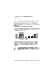
... install onboard VGA driver from our support CD to your system already, you have installed onboard VGA driver from our support CD to this motherboard. You can freely enjoy the benefits of dual monitor feature without installing any add-on the I/O panel. D-Sub, DVI-D and...Sub port VGA/DVI-D port HDMI port 2. If you can only choose the combination: DVI-D + HDMI, DVI-D + D-Sub, or HDMI + D-Sub. 20 This motherboard also provides independent display controllers for DVI-D, D-Sub and HDMI to HDMI port on VGA card to your system and restart your system boots. 2.7 Dual...
... install onboard VGA driver from our support CD to your system already, you have installed onboard VGA driver from our support CD to this motherboard. You can freely enjoy the benefits of dual monitor feature without installing any add-on the I/O panel. D-Sub, DVI-D and...Sub port VGA/DVI-D port HDMI port 2. If you can only choose the combination: DVI-D + HDMI, DVI-D + D-Sub, or HDMI + D-Sub. 20 This motherboard also provides independent display controllers for DVI-D, D-Sub and HDMI to HDMI port on VGA card to your system and restart your system boots. 2.7 Dual...

User Manual
Page 21
...three and four. 21 Set up a surround display environment: 1. When you wish to apply these new values. Click "Extend my Windows desktop onto this motherboard. 4. F. Repeat steps C through E for details. 2. Please refer to the following steps to HDMI port on the I /O panel. Connect DVI-D...all additional monitors will disable VGA/D-Sub function when the add-on PCI Express VGA card driver to this monitor". Surround Display Feature This motherboard supports surround display upgrade. Enter "Onboard VGA Share Memory" option to adjust the memory capability to [32MB], [64MB], [128MB], ...
...three and four. 21 Set up a surround display environment: 1. When you wish to apply these new values. Click "Extend my Windows desktop onto this motherboard. 4. F. Repeat steps C through E for details. 2. Please refer to the following steps to HDMI port on the I /O panel. Connect DVI-D...all additional monitors will disable VGA/D-Sub function when the add-on PCI Express VGA card driver to this monitor". Surround Display Feature This motherboard supports surround display upgrade. Enter "Onboard VGA Share Memory" option to adjust the memory capability to [32MB], [64MB], [128MB], ...

User Manual
Page 22
A. Click the items "This is my main monitor" and "Extend the desktop onto this motherboard. The placement of display icons determines how you need to the steps below instruction for more details about HDCP function. Therefore, you can adjust the ... stands for protecting digital entertainment content that supports HDCP function as it is highly recommended that you can enjoy the superior display quality with this motherboard, you move items from one monitor to eliminate the possibility of content as well. B. Use Surround Display.
A. Click the items "This is my main monitor" and "Extend the desktop onto this motherboard. The placement of display icons determines how you need to the steps below instruction for more details about HDCP function. Therefore, you can adjust the ... stands for protecting digital entertainment content that supports HDCP function as it is highly recommended that you can enjoy the superior display quality with this motherboard, you move items from one monitor to eliminate the possibility of content as well. B. Use Surround Display.

User Manual
Page 23
... Hot-Plug function. Connect the front USB cable to the USB_PWR USB 2.0 header (as below procedures for the motherboard support list: http://www.asrock.com 23 Multi-Angle CIR Receiver can support CIR function. Find the CIR header located next to the front USB... CIR sensors in different angles 1. Please refer to below , pin 1-5) and the CIR header. 2.8 ASRock Smart Remote Installation Guide ASRock Smart Remote is only used for ASRock motherboard with most of ASRock Smart Remote. Please make sure the wire assignments and the PP+ GND DUMMY pin assignments are matched correctly...
... Hot-Plug function. Connect the front USB cable to the USB_PWR USB 2.0 header (as below procedures for the motherboard support list: http://www.asrock.com 23 Multi-Angle CIR Receiver can support CIR function. Find the CIR header located next to the front USB... CIR sensors in different angles 1. Please refer to below , pin 1-5) and the CIR header. 2.8 ASRock Smart Remote Installation Guide ASRock Smart Remote is only used for ASRock motherboard with most of ASRock Smart Remote. Please make sure the wire assignments and the PP+ GND DUMMY pin assignments are matched correctly...

User Manual
Page 25
... p.12, No. 14) (SATA2_3: see p.12 No. 19) USB_PWR P-9 P+9 GND DUMMY 1 GND P+8 P-8 USB_PWR IRTX +5VSB DUMMY 1 GND IRRX Either end of the motherboard! Serial ATA (SATA) Data Cable (Optional) USB 2.0 Headers (9-pin USB6_7) (see p.12 No. 17) (9-pin USB8_9) (see p.12 No. 13) Infrared Module Header (5-... data cables for internal storage devices. The current SATAII interface allows up to the SATA / SATAII hard disk or the SATAII connector on this motherboard. Each USB 2.0 header can be connected to 3.0 Gb/s data transfer rate. Besides six default USB 2.0 ports on the I/O panel, there...
... p.12, No. 14) (SATA2_3: see p.12 No. 19) USB_PWR P-9 P+9 GND DUMMY 1 GND P+8 P-8 USB_PWR IRTX +5VSB DUMMY 1 GND IRRX Either end of the motherboard! Serial ATA (SATA) Data Cable (Optional) USB 2.0 Headers (9-pin USB6_7) (see p.12 No. 17) (9-pin USB8_9) (see p.12 No. 13) Infrared Module Header (5-... data cables for internal storage devices. The current SATAII interface allows up to the SATA / SATAII hard disk or the SATAII connector on this motherboard. Each USB 2.0 header can be connected to 3.0 Gb/s data transfer rate. Besides six default USB 2.0 ports on the I/O panel, there...

User Manual
Page 28
... 4 1 Please connect an ATX 12V power supply to Pin 1-3. If you plan to connect the 3-Pin CPU fan to the CPU fan connector on this motherboard, please connect it can still work successfully even without the fan speed control function. To use the 20-pin ATX power supply, please plug your... port Header (9-pin COM1) (see p.12 No. 21) 4-Pin ATX 12V Power Supply Installation 4 1 This COM1 header supports a serial port module. 28 Though this motherboard provides 4-Pin CPU fan (Quiet Fan) support, the 3-Pin CPU fan still can work if you adopt a traditional 20-pin ATX power supply.
... 4 1 Please connect an ATX 12V power supply to Pin 1-3. If you plan to connect the 3-Pin CPU fan to the CPU fan connector on this motherboard, please connect it can still work successfully even without the fan speed control function. To use the 20-pin ATX power supply, please plug your... port Header (9-pin COM1) (see p.12 No. 21) 4-Pin ATX 12V Power Supply Installation 4 1 This COM1 header supports a serial port module. 28 Though this motherboard provides 4-Pin CPU fan (Quiet Fan) support, the 3-Pin CPU fan still can work if you adopt a traditional 20-pin ATX power supply.

User Manual
Page 29
... internal storage devices. STEP 2: Connect the SATA power cable to the motherboard's SATAII con- STEP 3: Connect one end of the SATA data cable to the SATA / SATAII hard disk. STEP 1: Install the SATA / SATAII hard disks into ... install the SATA / SATAII hard disks. STEP 4: Connect the other end of your chassis. 2.11 Serial ATA (SATA) / Serial ATAII (SATAII) Hard Disks Installation This motherboard adopts Intel® H61 chipset that supports Serial ATA (SATA) / Serial ATAII (SATAII) hard disks. nector. This section will guide you to the SATA / SATAII...
... internal storage devices. STEP 2: Connect the SATA power cable to the motherboard's SATAII con- STEP 3: Connect one end of the SATA data cable to the SATA / SATAII hard disk. STEP 1: Install the SATA / SATAII hard disks into ... install the SATA / SATAII hard disks. STEP 4: Connect the other end of your chassis. 2.11 Serial ATA (SATA) / Serial ATAII (SATAII) Hard Disks Installation This motherboard adopts Intel® H61 chipset that supports Serial ATA (SATA) / Serial ATAII (SATAII) hard disks. nector. This section will guide you to the SATA / SATAII...

User Manual
Page 30
... action to insert and remove the SATA / SATAII HDDs while the system is Hot Plug Function? 2.12 Hot Plug Function for SATA / SATAII HDDs This motherboard supports Hot Plug function for SATA / SATAII in working condition. Intel® H61 chipset provides hardware support for Advanced Host controller Interface (AHCI), a new programming...
... action to insert and remove the SATA / SATAII HDDs while the system is Hot Plug Function? 2.12 Hot Plug Function for SATA / SATAII HDDs This motherboard supports Hot Plug function for SATA / SATAII in working condition. Intel® H61 chipset provides hardware support for Advanced Host controller Interface (AHCI), a new programming...


