User Manual
Page 4
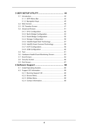
...UEFI SETUP UTILITY 44 3.1 Introduction 44 3.1.1 UEFI Menu Bar 44 3.1.2 Navigation Keys 45 3.2 Main Screen 45 3.3 OC Tweaker Screen 47 3.4 Advanced Screen 51 3.4.1 CPU Configuration 52 3.4.2 North Bridge Configuration 54 3.4.3 South Bridge Configuration 55 3.4.4 Storage Configuration 56 3.4.5 Intel(R) Rapid Start Technology 57 3.4.6 Intel(R) Smart Connect Technology 58 3.4.7 ACPI Configuration 59 3.4.8 USB Configuration 60 3.5 Tool 61 3.6 Hardware Health Event Monitoring Screen 63 3.7 Boot Screen 64 3.8 Security Screen 66 3.9 Exit Screen 67 4 Software Support 68 4.1 Install...
...UEFI SETUP UTILITY 44 3.1 Introduction 44 3.1.1 UEFI Menu Bar 44 3.1.2 Navigation Keys 45 3.2 Main Screen 45 3.3 OC Tweaker Screen 47 3.4 Advanced Screen 51 3.4.1 CPU Configuration 52 3.4.2 North Bridge Configuration 54 3.4.3 South Bridge Configuration 55 3.4.4 Storage Configuration 56 3.4.5 Intel(R) Rapid Start Technology 57 3.4.6 Intel(R) Smart Connect Technology 58 3.4.7 ACPI Configuration 59 3.4.8 USB Configuration 60 3.5 Tool 61 3.6 Hardware Health Event Monitoring Screen 63 3.7 Boot Screen 64 3.8 Security Screen 66 3.9 Exit Screen 67 4 Software Support 68 4.1 Install...
User Manual
Page 5
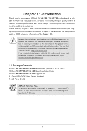
...) ASRock H61M-VG3 / H61M-VS3 Quick Installation Guide ASRock H61M-VG3 / H61M-VS3 Support CD 2 x Serial ATA (SATA) Data Cables (Optional) 1 x I/O Panel Shield ASRock Reminds You... Chapter 3 and 4 contain the configuration guide to AHCI mode. 5 Chapter 1: Introduction Thank you are using. ASRock website http://www.asrock.com If you require technical support related to quality and endurance. To get better performance in Windows® 8 / 8 64-bit / 7 / 7 64-bit / VistaTM / VistaTM 64-bit, it is recommended to set the BIOS option in Storage Configuration to BIOS setup...
...) ASRock H61M-VG3 / H61M-VS3 Quick Installation Guide ASRock H61M-VG3 / H61M-VS3 Support CD 2 x Serial ATA (SATA) Data Cables (Optional) 1 x I/O Panel Shield ASRock Reminds You... Chapter 3 and 4 contain the configuration guide to AHCI mode. 5 Chapter 1: Introduction Thank you are using. ASRock website http://www.asrock.com If you require technical support related to quality and endurance. To get better performance in Windows® 8 / 8 64-bit / 7 / 7 64-bit / VistaTM / VistaTM 64-bit, it is recommended to set the BIOS option in Storage Configuration to BIOS setup...

User Manual
Page 6
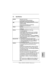
...; Sandy Bridge CPU. 6 Supports Intel® Extreme Memory Profile (XMP) 1.3 / 1.2 with Intel® Ivy Bridge CPU - 1 x PCI Express 3.0 x16 slot (blue @ x16 mode) * PCIE 3.0 is only supported with Intel® Ivy Bridge CPU. Max. 1.2 Specifications Platform CPU Chipset Memory Expansion Slot Graphics - Micro ATX Form Factor - Supports Intel® Turbo Boost 2.0 Technology - Pixel Shader 5.0, DirectX 11 with Intel® Ivy Bridge CPU. With Intel® Sandy Bridge CPU, it only supports PCIE 2.0. - 1 x PCI Express 2.0 x1 slot * Intel®...
...; Sandy Bridge CPU. 6 Supports Intel® Extreme Memory Profile (XMP) 1.3 / 1.2 with Intel® Ivy Bridge CPU - 1 x PCI Express 3.0 x16 slot (blue @ x16 mode) * PCIE 3.0 is only supported with Intel® Ivy Bridge CPU. Max. 1.2 Specifications Platform CPU Chipset Memory Expansion Slot Graphics - Micro ATX Form Factor - Supports Intel® Turbo Boost 2.0 Technology - Pixel Shader 5.0, DirectX 11 with Intel® Ivy Bridge CPU. With Intel® Sandy Bridge CPU, it only supports PCIE 2.0. - 1 x PCI Express 2.0 x1 slot * Intel®...

User Manual
Page 9
... BIOS file to enter your Windows® desktop in a few seconds. In Hardware Monitor, it shows the fan speed and temperature for your USB flash drive, floppy disk or hard drive, then you to shorten boot up time. ASRock Instant Flash ASRock Instant Flash is an all-in-one tool to ne-tune different system functions in a user-friendly interface, which normally enable the Sleep/Standby and Hibernation modes in Windows® to adjust. ASRock Instant Boot ASRock Instant Boot...
... BIOS file to enter your Windows® desktop in a few seconds. In Hardware Monitor, it shows the fan speed and temperature for your USB flash drive, floppy disk or hard drive, then you to shorten boot up time. ASRock Instant Flash ASRock Instant Flash is an all-in-one tool to ne-tune different system functions in a user-friendly interface, which normally enable the Sleep/Standby and Hibernation modes in Windows® to adjust. ASRock Instant Boot ASRock Instant Boot...

User Manual
Page 13
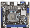
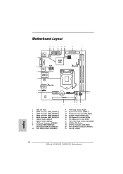
... SPI Flash 2 SATA2 Connector (SATA_1 (PORT 1)) 3 SATA2 Connector (SATA_0 (PORT 0)) 4 SATA2 Connector (SATA_2 (PORT 4)) 5 SATA2 Connector (SATA_3 (PORT 5)) 6 USB 2.0 Header (USB6_7) 7 USB 2.0 Header (USB4_5) 8 ATX Power Connector (ATXPWR1) 9 2 x 240-pin DDR3 DIMM Slots (Dual Channel: DDR3_A1, DDR3_B1) 10 Clear CMOS Jumper (CLRCMOS1) 11 Power LED Header (PLED1) 12 System Panel Header (PANEL1) 13 Chassis Fan Connector (CHA_FAN1) 14 Chassis Intrusion Header (CI1) 15 PCI Express 3.0 x16 Slot (PCIE2) 16 PCI Express 2.0 x1 Slot (PCIE1) 17 Front Panel Audio Header (HD_AUDIO1) 18 1155-Pin CPU Socket...
... SPI Flash 2 SATA2 Connector (SATA_1 (PORT 1)) 3 SATA2 Connector (SATA_0 (PORT 0)) 4 SATA2 Connector (SATA_2 (PORT 4)) 5 SATA2 Connector (SATA_3 (PORT 5)) 6 USB 2.0 Header (USB6_7) 7 USB 2.0 Header (USB4_5) 8 ATX Power Connector (ATXPWR1) 9 2 x 240-pin DDR3 DIMM Slots (Dual Channel: DDR3_A1, DDR3_B1) 10 Clear CMOS Jumper (CLRCMOS1) 11 Power LED Header (PLED1) 12 System Panel Header (PANEL1) 13 Chassis Fan Connector (CHA_FAN1) 14 Chassis Intrusion Header (CI1) 15 PCI Express 3.0 x16 Slot (PCIE2) 16 PCI Express 2.0 x1 Slot (PCIE1) 17 Front Panel Audio Header (HD_AUDIO1) 18 1155-Pin CPU Socket...

User Manual
Page 22
... corresponding connectors of D-sub. Install the PCI Express VGA card on each monitor. Then connect other monitor cables to display a large number on PCIE2 slot. Set up a multi monitor environment: 1. Press or to page 21 for proper expansion card installation procedures for details. 2. Enter "Onboard VGA Share Memory" option to adjust the memory capability to [32MB], [64MB], [128MB], [256MB] or [512MB] to enable the function of the add-on PCI Express VGA card on PCI Express VGA card driver to set up a multi-monitor display...
... corresponding connectors of D-sub. Install the PCI Express VGA card on each monitor. Then connect other monitor cables to display a large number on PCIE2 slot. Set up a multi monitor environment: 1. Press or to page 21 for proper expansion card installation procedures for details. 2. Enter "Onboard VGA Share Memory" option to adjust the memory capability to [32MB], [64MB], [128MB], [256MB] or [512MB] to enable the function of the add-on PCI Express VGA card on PCI Express VGA card driver to set up a multi-monitor display...

User Manual
Page 32
...-bit OS on the support CD driver page. Therefore, the drivers you install can be auto-detected and listed on your SATA / SATA2 HDDs without RAID functions, please follow the order from up , press key, and then a window for boot devices selection appears. A. STEP 2: Make a SATA / SATA2 driver diskette. (Please use an USB floppy or a floppy disk.) A. C. WARNING! Please insert a floppy diskette into the floppy diskette. 32 Then, the drivers compatible to boot your system. Enter UEFI SETUP UTILITY Advanced screen Storage Configuration...
...-bit OS on the support CD driver page. Therefore, the drivers you install can be auto-detected and listed on your SATA / SATA2 HDDs without RAID functions, please follow the order from up , press key, and then a window for boot devices selection appears. A. STEP 2: Make a SATA / SATA2 driver diskette. (Please use an USB floppy or a floppy disk.) A. C. WARNING! Please insert a floppy diskette into the floppy diskette. 32 Then, the drivers compatible to boot your system. Enter UEFI SETUP UTILITY Advanced screen Storage Configuration...

User Manual
Page 44
... Useful tools H/W Monitor To display current hardware status Boot To set up the default system device to locate and load the Operating System Security To set up the computer. You may not exactly match what you see on your screen. 3.1.1 UEFI Menu Bar The top of the screen has a menu bar with its test routines. Please press or during the Power-On-Self-Test (POST) to enter the UEFI SETUP UTILITY...
... Useful tools H/W Monitor To display current hardware status Boot To set up the default system device to locate and load the Operating System Security To set up the computer. You may not exactly match what you see on your screen. 3.1.1 UEFI Menu Bar The top of the screen has a menu bar with its test routines. Please press or during the Power-On-Self-Test (POST) to enter the UEFI SETUP UTILITY...

User Manual
Page 52
... Memory Protection No-Execution (NX) Memory Protection Technology is [All]. The default value is [Auto]. Set to OS. CPU C3 State Support Use this to enable or disable CPU C6 (ACPI C3) report to [Enabled] if using Microsoft® Windows® XP, VistaTM, 7, 8, or Linux kernel version 2.4.18 or higher. Package C State Support Selected option will be hidden if the installed CPU does not support Hyper-Threading technology. Enhance Halt State (C1E) All processors support...
... Memory Protection No-Execution (NX) Memory Protection Technology is [All]. The default value is [Auto]. Set to OS. CPU C3 State Support Use this to enable or disable CPU C6 (ACPI C3) report to [Enabled] if using Microsoft® Windows® XP, VistaTM, 7, 8, or Linux kernel version 2.4.18 or higher. Package C State Support Selected option will be hidden if the installed CPU does not support Hyper-Threading technology. Enhance Halt State (C1E) All processors support...

User Manual
Page 54
... to set onboard VGA share memory feature. IGPU Multi-Moniter This allows you to select [Onboard] or [PCI Express] as the boot graphic adapter priority. The default value is [Auto]. The default value is [PCI Express]. The default value is [Disabled]. 3.4.2 North Bridge Configuration Primary Graphics Adapter This allows you to enable or disable IGPU Multi-Moniter. Render Standby Use this to enable or disable Render Standby by Internal Graphics Device. VT-d Use this to enable or disable Intel...
... to set onboard VGA share memory feature. IGPU Multi-Moniter This allows you to select [Onboard] or [PCI Express] as the boot graphic adapter priority. The default value is [Auto]. The default value is [PCI Express]. The default value is [Disabled]. 3.4.2 North Bridge Configuration Primary Graphics Adapter This allows you to enable or disable IGPU Multi-Moniter. Render Standby Use this to enable or disable Render Standby by Internal Graphics Device. VT-d Use this to enable or disable Intel...

User Manual
Page 56
... improve SATA disk performance but IDE mode does not have these advantages. SATA Aggressive Link Power Management Use this item to enable or disable the SATA Controller feature. The default value is [AHCI Mode]. 3.4.4 Storage Configuration SATA Controller(s) Use this item to configure SATA Aggressive Link Power Management. SATA Mode Selection Use this item to select SATA mode. Configuration options: [Disabled] and [Enabled]. 56 Configuration options: [IDE Mode], [AHCI Mode] and [Disabled]. Hard Disk S.M.A.R.T. Use this to enable or disable the S.M.A.R.T. (Self-Monitoring...
... improve SATA disk performance but IDE mode does not have these advantages. SATA Aggressive Link Power Management Use this item to enable or disable the SATA Controller feature. The default value is [AHCI Mode]. 3.4.4 Storage Configuration SATA Controller(s) Use this item to configure SATA Aggressive Link Power Management. SATA Mode Selection Use this item to select SATA mode. Configuration options: [Disabled] and [Enabled]. 56 Configuration options: [IDE Mode], [AHCI Mode] and [Disabled]. Hard Disk S.M.A.R.T. Use this to enable or disable the S.M.A.R.T. (Self-Monitoring...

User Manual
Page 60
...[Disabled] to enter OS. [UEFI Setup Only] - Please refer to below descriptions for legacy USB. [Auto] - USB devices are allowed to use under UEFI setup and Windows / Linux OS. 60 The default value is selected. Enables legacy support if USB devices are four configuration options: [Enabled], [Auto], [Disabled] and [UEFI Setup Only]. CSM Please disable CSM when you have USB compatibility issue, it is [Enabled]. 3.4.8 USB Configuration USB 2.0 Controller Use this option to select legacy support for USB devices. There are connected. [Disabled] - USB devices are not allowed to use...
...[Disabled] to enter OS. [UEFI Setup Only] - Please refer to below descriptions for legacy USB. [Auto] - USB devices are allowed to use under UEFI setup and Windows / Linux OS. 60 The default value is selected. Enables legacy support if USB devices are four configuration options: [Enabled], [Auto], [Disabled] and [UEFI Setup Only]. CSM Please disable CSM when you have USB compatibility issue, it is [Enabled]. 3.4.8 USB Configuration USB 2.0 Controller Use this option to select legacy support for USB devices. There are connected. [Disabled] - USB devices are not allowed to use...

User Manual
Page 63
... feature. CPU Fan Setting This allows you to enable or disable case open has been detected. Use this section, it allows you to monitor the status of the hardware on your system, including the parameters of previous chassis intrusion status. 63 The default is value [Enabled]. 3.6 Hardware Health Event Monitoring Screen In this option to keep or clear the record of the CPU temperature, motherboard temperature, CPU fan speed, chassis fan speed, and the critical voltage.
... feature. CPU Fan Setting This allows you to enable or disable case open has been detected. Use this section, it allows you to monitor the status of the hardware on your system, including the parameters of previous chassis intrusion status. 63 The default is value [Enabled]. 3.6 Hardware Health Event Monitoring Screen In this option to keep or clear the record of the CPU temperature, motherboard temperature, CPU fan speed, chassis fan speed, and the critical voltage.
User Manual
Page 68
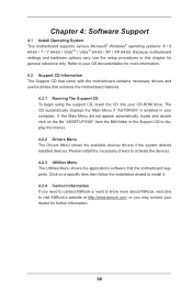
... for more about ASRock, welcome to display the menus. 4.2.2 Drivers Menu The Drivers Menu shows the available devices drivers if the system detects installed devices. Chapter 4: Software Support 4.1 Install Operating System This motherboard supports various Microsoft® Windows® operating systems: 8 / 8 64-bit / 7 / 7 64-bit / VistaTM / VistaTM 64-bit / XP / XP 64-bit. Please install the necessary drivers to your CD-ROM drive. Because motherboard settings and hardware options vary, use the setup procedures in the Support CD to visit...
... for more about ASRock, welcome to display the menus. 4.2.2 Drivers Menu The Drivers Menu shows the available devices drivers if the system detects installed devices. Chapter 4: Software Support 4.1 Install Operating System This motherboard supports various Microsoft® Windows® operating systems: 8 / 8 64-bit / 7 / 7 64-bit / VistaTM / VistaTM 64-bit / XP / XP 64-bit. Please install the necessary drivers to your CD-ROM drive. Because motherboard settings and hardware options vary, use the setup procedures in the Support CD to visit...
Quick Installation Guide
Page 2
... (PORT 5)) 6 USB 2.0 Header (USB6_7) 7 USB 2.0 Header (USB4_5) 8 ATX Power Connector (ATXPWR1) 9 2 x 240-pin DDR3 DIMM Slots (Dual Channel: DDR3_A1, DDR3_B1) 10 Clear CMOS Jumper (CLRCMOS1) 11 Power LED Header (PLED1) 12 System Panel Header (PANEL1) 13 Chassis Fan Connector (CHA_FAN1) 14 Chassis Intrusion Header (CI1) 15 PCI Express 3.0 x16 Slot (PCIE2) 16 PCI Express 2.0 x1 Slot (PCIE1) 17 Front Panel Audio Header (HD_AUDIO1) 18 1155-Pin CPU Socket 19 CPU Fan Connector (CPU_FAN1) 20 ATX 12V Power Connector (ATX12V1) 21 Intel H61 Chipset English 2 ASRock H61M-VG3 / H61M-VS3 Motherboard
... (PORT 5)) 6 USB 2.0 Header (USB6_7) 7 USB 2.0 Header (USB4_5) 8 ATX Power Connector (ATXPWR1) 9 2 x 240-pin DDR3 DIMM Slots (Dual Channel: DDR3_A1, DDR3_B1) 10 Clear CMOS Jumper (CLRCMOS1) 11 Power LED Header (PLED1) 12 System Panel Header (PANEL1) 13 Chassis Fan Connector (CHA_FAN1) 14 Chassis Intrusion Header (CI1) 15 PCI Express 3.0 x16 Slot (PCIE2) 16 PCI Express 2.0 x1 Slot (PCIE1) 17 Front Panel Audio Header (HD_AUDIO1) 18 1155-Pin CPU Socket 19 CPU Fan Connector (CPU_FAN1) 20 ATX 12V Power Connector (ATX12V1) 21 Intel H61 Chipset English 2 ASRock H61M-VG3 / H61M-VS3 Motherboard
Quick Installation Guide
Page 4
... motherboard and step-bystep installation guide. You may find the latest VGA cards and CPU support lists on ASRock website without notice. To get better performance in Windows® 8 / 8 64-bit / 7 / 7 64-bit / VistaTM / VistaTM 64-bit, it is recommended to AHCI mode. 1. More detailed information of this manual occur, the updated version will be subject to change without further notice. Because the motherboard specifications and the BIOS software...
... motherboard and step-bystep installation guide. You may find the latest VGA cards and CPU support lists on ASRock website without notice. To get better performance in Windows® 8 / 8 64-bit / 7 / 7 64-bit / VistaTM / VistaTM 64-bit, it is recommended to AHCI mode. 1. More detailed information of this manual occur, the updated version will be subject to change without further notice. Because the motherboard specifications and the BIOS software...
Quick Installation Guide
Page 5
... Bridge CPU - Supports Intel® Rapid Start Technology and Smart Connect Technology - Dual Channel DDR3 Memory Technology - 2 x DDR3 DIMM slots - Pixel Shader 4.1, DirectX 10.1 with Intel® Ivy Bridge CPU. Max. Micro ATX Form Factor - Supports K-Series unlocked CPU - Pixel Shader 5.0, DirectX 11 with Intel® Sandy Bridge CPU. - Solid Capacitor for CPU power (H61M-VS3) - Supports Intel® Extreme Memory Profile (XMP) 1.3 / 1.2 with Intel® Ivy Bridge CPU - 1 x PCI Express 3.0 x16 slot (blue @ x16 mode) * PCIE 3.0 is only supported...
... Bridge CPU - Supports Intel® Rapid Start Technology and Smart Connect Technology - Dual Channel DDR3 Memory Technology - 2 x DDR3 DIMM slots - Pixel Shader 4.1, DirectX 10.1 with Intel® Ivy Bridge CPU. Max. Micro ATX Form Factor - Supports K-Series unlocked CPU - Pixel Shader 5.0, DirectX 11 with Intel® Sandy Bridge CPU. - Solid Capacitor for CPU power (H61M-VS3) - Supports Intel® Extreme Memory Profile (XMP) 1.3 / 1.2 with Intel® Ivy Bridge CPU - 1 x PCI Express 3.0 x16 slot (blue @ x16 mode) * PCIE 3.0 is only supported...
Quick Installation Guide
Page 6
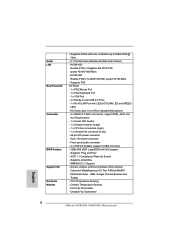
... header - 1 x Chassis Intrusion header - 1 x CPU Fan connectors (4-pin) - 1 x Chassis Fan connector (3-pin) - 24 pin ATX power connector - 4 pin 12V power connector - Front panel audio connector - 2 x USB 2.0 headers (support 4 USB 2.0 ports) - 32Mb AMI UEFI Legal BIOS with max. CPU Fan Tachometer - H61M-VS3 Realtek PCIE x1 LAN RTL8105E, speed 10/100 Mb/s - Supports PXE I /O Connector BIOS Feature Support CD Hardware Monitor - Chassis Temperature Sensing - ACPI 1.1 Compliance Wake Up Events - Audio LAN Rear Panel I /O Panel - 1 x PS/2 Mouse Port - 1 x PS/2 Keyboard Port - 1 x VGA Port...
... header - 1 x Chassis Intrusion header - 1 x CPU Fan connectors (4-pin) - 1 x Chassis Fan connector (3-pin) - 24 pin ATX power connector - 4 pin 12V power connector - Front panel audio connector - 2 x USB 2.0 headers (support 4 USB 2.0 ports) - 32Mb AMI UEFI Legal BIOS with max. CPU Fan Tachometer - H61M-VS3 Realtek PCIE x1 LAN RTL8105E, speed 10/100 Mb/s - Supports PXE I /O Connector BIOS Feature Support CD Hardware Monitor - Chassis Temperature Sensing - ACPI 1.1 Compliance Wake Up Events - Audio LAN Rear Panel I /O Panel - 1 x PS/2 Mouse Port - 1 x PS/2 Keyboard Port - 1 x VGA Port...
Quick Installation Guide
Page 8
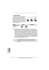
... not clear the CMOS right after you update the BIOS. Please adjust the BIOS option "Clear Status" to default setup, please turn off the computer and unplug the power cord from the power supply. To clear and reset the system parameters to clear the record of previous chassis intrusion status. Please be noted that the password, date, time and user default profile will be detected. The illustration shows a 3-pin jumper whose...
... not clear the CMOS right after you update the BIOS. Please adjust the BIOS option "Clear Status" to default setup, please turn off the computer and unplug the power cord from the power supply. To clear and reset the system parameters to clear the record of previous chassis intrusion status. Please be noted that the password, date, time and user default profile will be detected. The illustration shows a 3-pin jumper whose...
Quick Installation Guide
Page 13
... BIOS Setup Utility. Software Support CD information This motherboard supports various Microsoft® Windows® operating systems: 8 / 8 64-bit / 7 / 7 64-bit / VistaTM / VistaTM 64-bit / XP / XP 64-bit. For the detailed information about BIOS Setup, please refer to display the menus. 13 ASRock H61M-VG3 / H61M-VS3 Motherboard English The BIOS Setup program is a menu-driven program, which allows you to enter BIOS Setup utility; It will enhance motherboard features. 2. otherwise, POST continues with the motherboard contains necessary drivers and useful utilities...
... BIOS Setup Utility. Software Support CD information This motherboard supports various Microsoft® Windows® operating systems: 8 / 8 64-bit / 7 / 7 64-bit / VistaTM / VistaTM 64-bit / XP / XP 64-bit. For the detailed information about BIOS Setup, please refer to display the menus. 13 ASRock H61M-VG3 / H61M-VS3 Motherboard English The BIOS Setup program is a menu-driven program, which allows you to enter BIOS Setup utility; It will enhance motherboard features. 2. otherwise, POST continues with the motherboard contains necessary drivers and useful utilities...


