User Manual
Page 5
... updated version will be available on ASRock website as well. To get better performance in Windows® 8 / 8 64-bit / 7 / 7 64-bit / VistaTM / VistaTM 64-bit, it is recommended to set the BIOS ...BIOS setup and information of the motherboard and stepby-step guide to this manual, chapter 1 and 2 contain introduction of the Support CD. ASRock website http://www.asrock.com If you require technical support related to the hardware installation. www.asrock.com/support/index.asp 1.1 Package Contents ASRock H61M-VG3 / H61M-VS3 Motherboard (Micro ATX Form Factor) ASRock H61M-VG3 / H61M...
... updated version will be available on ASRock website as well. To get better performance in Windows® 8 / 8 64-bit / 7 / 7 64-bit / VistaTM / VistaTM 64-bit, it is recommended to set the BIOS ...BIOS setup and information of the motherboard and stepby-step guide to this manual, chapter 1 and 2 contain introduction of the Support CD. ASRock website http://www.asrock.com If you require technical support related to the hardware installation. www.asrock.com/support/index.asp 1.1 Package Contents ASRock H61M-VG3 / H61M-VS3 Motherboard (Micro ATX Form Factor) ASRock H61M-VG3 / H61M...

User Manual
Page 9
... Windows®. In Hardware Monitor, it shows the major readings of your system. ASRock Instant Boot ASRock Instant Boot allows you to turn on your Windows® desktop in a few seconds. This convenient BIOS update tool allows you to update system BIOS without preparing an additional floppy diskette or other complicated flash utility. Please be used...
... Windows®. In Hardware Monitor, it shows the major readings of your system. ASRock Instant Boot ASRock Instant Boot allows you to turn on your Windows® desktop in a few seconds. This convenient BIOS update tool allows you to update system BIOS without preparing an additional floppy diskette or other complicated flash utility. Please be used...

User Manual
Page 11
...seconds to logon to Windows® 8 from our servers. No more waiting! If power loss occurs during the BIOS update process, ASRock Crashless BIOS will completely change your USB disk. Please note that you must be placed in order to enable this feature. You... in the root directory of failing. Only USB2.0 ports support this function. ASRock Internet Flash ASRock Internet Flash searches for available UEFI firmware updates from a cold boot. ASRock Crashless BIOS ASRock Crashless BIOS allows users to update their BIOS without fear of your user experience and behavior. 11
...seconds to logon to Windows® 8 from our servers. No more waiting! If power loss occurs during the BIOS update process, ASRock Crashless BIOS will completely change your USB disk. Please note that you must be placed in order to enable this feature. You... in the root directory of failing. Only USB2.0 ports support this function. ASRock Internet Flash ASRock Internet Flash searches for available UEFI firmware updates from a cold boot. ASRock Crashless BIOS ASRock Crashless BIOS allows users to update their BIOS without fear of your user experience and behavior. 11

User Manual
Page 24
...record of previous chassis intrusion status. 24 After waiting for 5 seconds. If you need to clear the CMOS when you just finish updating the BIOS, you must boot up the system first, and then shut it down before you clear the CMOS, the case open may be cleared... the data in CMOS. Jumper Setting Description Clear CMOS Jumper (CLRCMOS1) (see p.13, No. 10) Default Clear CMOS Note: CLRCMOS1 allows you update the BIOS. When the jumper cap is placed on pins, the jumper is removed. However, please do the clear-CMOS action. 2.8 Jumpers Setup The illustration ...
...record of previous chassis intrusion status. 24 After waiting for 5 seconds. If you need to clear the CMOS when you just finish updating the BIOS, you must boot up the system first, and then shut it down before you clear the CMOS, the case open may be cleared... the data in CMOS. Jumper Setting Description Clear CMOS Jumper (CLRCMOS1) (see p.13, No. 10) Default Clear CMOS Note: CLRCMOS1 allows you update the BIOS. When the jumper cap is placed on pins, the jumper is removed. However, please do the clear-CMOS action. 2.8 Jumpers Setup The illustration ...
Quick Installation Guide
Page 4
...) ASRock H61M-VG3 / H61M-VS3 Quick Installation Guide ASRock H61M-VG3 / H61M-VS3 Support CD 2 x Serial ATA (SATA) Data Cables (Optional) 1 x I/O Panel Shield ASRock Reminds You... Introduction Thank you are using. You may find the latest VGA cards and CPU support lists on ASRock website without notice. Because the motherboard specifications and the BIOS software might be updated, the...
...) ASRock H61M-VG3 / H61M-VS3 Quick Installation Guide ASRock H61M-VG3 / H61M-VS3 Support CD 2 x Serial ATA (SATA) Data Cables (Optional) 1 x I/O Panel Shield ASRock Reminds You... Introduction Thank you are using. You may find the latest VGA cards and CPU support lists on ASRock website without notice. Because the motherboard specifications and the BIOS software might be updated, the...
Quick Installation Guide
Page 8
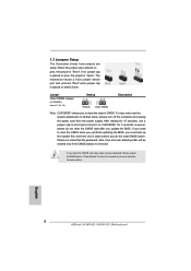
... system parameters to clear the record of previous chassis intrusion status. English 8 ASRock H61M-VG3 / H61M-VS3 Motherboard If no jumper cap is placed on pins, the jumper is placed on CLRCMOS1 for 5 seconds. Please adjust the BIOS option "Clear Status" to default setup, please turn off the computer and ...short pin2 and pin3 on these 2 pins. After waiting for 15 seconds, use a jumper cap to clear the data in CMOS. If you update the BIOS. The illustration shows a 3-pin jumper whose pin1 and pin2 are setup. However, please do the clear-CMOS action. 1.3 Jumpers Setup The ...
... system parameters to clear the record of previous chassis intrusion status. English 8 ASRock H61M-VG3 / H61M-VS3 Motherboard If no jumper cap is placed on pins, the jumper is placed on CLRCMOS1 for 5 seconds. Please adjust the BIOS option "Clear Status" to default setup, please turn off the computer and ...short pin2 and pin3 on these 2 pins. After waiting for 15 seconds, use a jumper cap to clear the data in CMOS. If you update the BIOS. The illustration shows a 3-pin jumper whose pin1 and pin2 are setup. However, please do the clear-CMOS action. 1.3 Jumpers Setup The ...


