User Manual
Page 7
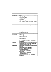
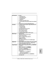
...Front panel audio connector - 2 x USB 2.0 headers (support 4 USB 2.0 ports) - 32Mb AMI BIOS - Instant Boot - Rear Panel I/O Connector BIOS Feature Support CD Unique Feature I/O Panel - 1 x PS/2 Mouse Port - 1 x PS/2 Keyboard Port - 1 x VGA/D-Sub Port - 1 x HDMI Port - 6 x Ready-to-Use USB 2.0 Ports - 1 x RJ-45 LAN Port with GUI support - Creative Sound Blaster X-Fi MB - CPU/Chassis/Power FAN connector - 24 pin ATX power connector - 4 pin 12V power connector - IGPU, DRAM, PCH, CPU PLL, VTT, VCCSA Voltage Multi-adjustment - ASRock Instant Flash (see CAUTION 7) - Good Night LED 7
...Front panel audio connector - 2 x USB 2.0 headers (support 4 USB 2.0 ports) - 32Mb AMI BIOS - Instant Boot - Rear Panel I/O Connector BIOS Feature Support CD Unique Feature I/O Panel - 1 x PS/2 Mouse Port - 1 x PS/2 Keyboard Port - 1 x VGA/D-Sub Port - 1 x HDMI Port - 6 x Ready-to-Use USB 2.0 Ports - 1 x RJ-45 LAN Port with GUI support - Creative Sound Blaster X-Fi MB - CPU/Chassis/Power FAN connector - 24 pin ATX power connector - 4 pin 12V power connector - IGPU, DRAM, PCH, CPU PLL, VTT, VCCSA Voltage Multi-adjustment - ASRock Instant Flash (see CAUTION 7) - Good Night LED 7
User Manual
Page 9
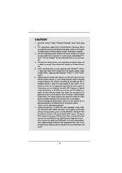
... complicated flash utility. This motherboard supports Dual Channel Memory Technology. Deep Color mode will be enabled only if the display supports 12bpc in Flash ROM. In Hardware Monitor, it shows the fan speed and temperature for system usage under Windows® 7 64-bit / 7 / VistaTM 64-bit / VistaTM. 6. CAUTION! 1. Due to the operating system limitation, the actual memory size may be noted that the USB flash drive or hard drive must use FAT32/16/12 fi...
... complicated flash utility. This motherboard supports Dual Channel Memory Technology. Deep Color mode will be enabled only if the display supports 12bpc in Flash ROM. In Hardware Monitor, it shows the fan speed and temperature for system usage under Windows® 7 64-bit / 7 / VistaTM 64-bit / VistaTM. 6. CAUTION! 1. Due to the operating system limitation, the actual memory size may be noted that the USB flash drive or hard drive must use FAT32/16/12 fi...
User Manual
Page 12
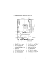
... Flash 8 SATA2 Connector (SATA2_1, Blue) 9 Chassis Fan Connector (CHA_FAN1) 10 SATA2 Connector (SATA2_0, Blue) 11 SATA2 Connector (SATA2_3, Blue) 12 SATA2 Connector (SATA2_2, Blue) 13 Chassis Speaker Header (SPEAKER 1, White) 14 System Panel Header (PANEL1, White) 15 USB 2.0 Header (USB6_7, Blue) 16 USB 2.0 Header (USB8_9, Blue) 17 COM Port Header (COM1) 18 Print Port Header (LPT1, White) 19 Front Panel Audio Header (HD_AUDIO1, White) 20 PCI Express 2.0 x1 Slot (PCIE2, White) 21 Clear CMOS Jumper (CLRCMOS1) 22 PCI Express 2.0 x16 Slot (PCIE1, Blue) 23 Power Fan Connector...
... Flash 8 SATA2 Connector (SATA2_1, Blue) 9 Chassis Fan Connector (CHA_FAN1) 10 SATA2 Connector (SATA2_0, Blue) 11 SATA2 Connector (SATA2_3, Blue) 12 SATA2 Connector (SATA2_2, Blue) 13 Chassis Speaker Header (SPEAKER 1, White) 14 System Panel Header (PANEL1, White) 15 USB 2.0 Header (USB6_7, Blue) 16 USB 2.0 Header (USB8_9, Blue) 17 COM Port Header (COM1) 18 Print Port Header (LPT1, White) 19 Front Panel Audio Header (HD_AUDIO1, White) 20 PCI Express 2.0 x1 Slot (PCIE2, White) 21 Clear CMOS Jumper (CLRCMOS1) 22 PCI Express 2.0 x16 Slot (PCIE1, Blue) 23 Power Fan Connector...

User Manual
Page 21
This motherboard also provides independent display controllers for HDMI and D-Sub to VGA/D-Sub port on the I /O panel, and connect D-Sub monitor cable to support dual VGA output so that HDMI and D-sub can drive same or different display contents. Connect HDMI monitor cable to VGA/HDMI port on VGA card to your system and restart your system boots. If you haven't installed onboard VGA driver yet, please install onboard VGA driver from our support CD to your system already, you can freely enjoy the bene...
This motherboard also provides independent display controllers for HDMI and D-Sub to VGA/D-Sub port on the I /O panel, and connect D-Sub monitor cable to support dual VGA output so that HDMI and D-sub can drive same or different display contents. Connect HDMI monitor cable to VGA/HDMI port on VGA card to your system and restart your system boots. If you haven't installed onboard VGA driver yet, please install onboard VGA driver from our support CD to your system already, you can freely enjoy the bene...

User Manual
Page 22
... support (HDMI and D-Sub) and external add-on PCI Express VGA cards, you can adjust the parameters of VGA/D-sub. Connect HDMI monitor cable to VGA/HDMI port on VGA card is inserted to enable the function of the multi-monitor according to the steps below. Please make sure that the value you do not adjust the UEFI setup, the default value of the system memory. Set up a surround display environment: 1. B. When you have installed...
... support (HDMI and D-Sub) and external add-on PCI Express VGA cards, you can adjust the parameters of VGA/D-sub. Connect HDMI monitor cable to VGA/HDMI port on VGA card is inserted to enable the function of the multi-monitor according to the steps below. Please make sure that the value you do not adjust the UEFI setup, the default value of the system memory. Set up a surround display environment: 1. B. When you have installed...
User Manual
Page 32
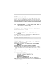
Enter UEFI SETUP UTILITY Advanced screen SATA Configuration. Therefore, the drivers you install can be auto-detected and listed on your SATA / SATAII HDDs without RAID functions, please follow the order from up , press key, and then a window for boot devices selection appears. Please select CD-ROM as the boot device. Then, the drivers compatible to your system can work properly. 2.14 Installing Windows® 7 / 7 64-bit / VistaTM / VistaTM 64-bit / XP / XP 64-bit Without RAID Functions...
Enter UEFI SETUP UTILITY Advanced screen SATA Configuration. Therefore, the drivers you install can be auto-detected and listed on your SATA / SATAII HDDs without RAID functions, please follow the order from up , press key, and then a window for boot devices selection appears. Please select CD-ROM as the boot device. Then, the drivers compatible to your system can work properly. 2.14 Installing Windows® 7 / 7 64-bit / VistaTM / VistaTM 64-bit / XP / XP 64-bit Without RAID Functions...
User Manual
Page 41
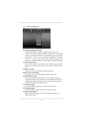
... supported through the native processor instructions HLT and MWAIT and requires no hardware support from the chipset. CPU C6 State Support Use this technology, such as Microsoft® Windows® XP / VistaTM / 7. 3.4.1 CPU Configuration Intel Hyper Threading Technology To enable this feature, it requires a computer system with an Intel processor that supports Hyper-Threading technology and an operating system that includes optimization for this to enable or disable CPU C6 (ACPI...
... supported through the native processor instructions HLT and MWAIT and requires no hardware support from the chipset. CPU C6 State Support Use this technology, such as Microsoft® Windows® XP / VistaTM / 7. 3.4.1 CPU Configuration Intel Hyper Threading Technology To enable this feature, it requires a computer system with an Intel processor that supports Hyper-Threading technology and an operating system that includes optimization for this to enable or disable CPU C6 (ACPI...
User Manual
Page 43
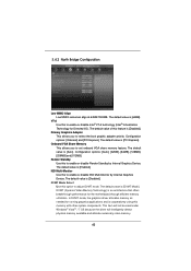
... boot graphic adapter priority. IGD Multi-Monitor Use this to set onboard VGA share memory feature. DVMT (Dynamic Video Memory Technology) is an architecture that offers breakthrough performance for running graphics applications and is [Disabled]. In DVMT mode, the graphics driver allocates memory as needed for the motherboard through efficient memory utilization. Primary Graphics Adapter This allows you to enable or disable Render Standby by Internal Graphics Device. The default value is [Auto]. DVMT Mode Select Use this memory...
... boot graphic adapter priority. IGD Multi-Monitor Use this to set onboard VGA share memory feature. DVMT (Dynamic Video Memory Technology) is an architecture that offers breakthrough performance for running graphics applications and is [Disabled]. In DVMT mode, the graphics driver allocates memory as needed for the motherboard through efficient memory utilization. Primary Graphics Adapter This allows you to enable or disable Render Standby by Internal Graphics Device. The default value is [Auto]. DVMT Mode Select Use this memory...

User Manual
Page 46
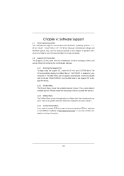
... options: [Disabled] and [Enabled]. 46 3.4.4 Storage Configuration SATA Mode Use this to enable or disable SATA Controller 1. AHCI (Advanced Host Controller Interface) supports NCQ and other new features that will improve SATA disk performance but IDE mode does not have these advantages. Hard Disk S.M.A.R.T. SATA Controller 1 Use this item to enable or disable the S.M.A.R.T. (Self-Monitoring, Analysis, and Reporting Technology) feature. The default value is installed, please select [Enhanced]. Use this item to select SATA mode. SATA Controller 0 Please select [Compatible...
... options: [Disabled] and [Enabled]. 46 3.4.4 Storage Configuration SATA Mode Use this to enable or disable SATA Controller 1. AHCI (Advanced Host Controller Interface) supports NCQ and other new features that will improve SATA disk performance but IDE mode does not have these advantages. Hard Disk S.M.A.R.T. SATA Controller 1 Use this item to enable or disable the S.M.A.R.T. (Self-Monitoring, Analysis, and Reporting Technology) feature. The default value is installed, please select [Enhanced]. Use this item to select SATA mode. SATA Controller 0 Please select [Compatible...

User Manual
Page 49
... Configuration USB 2.0 Controller Use this option to select legacy support for legacy USB. [Auto] - USB devices are allowed to use under UEFI setup and Windows / Linux OS. 49 The default value is recommended to select [Disabled] to enable or disable the use of these four options: [Enabled] - Legacy USB Support Use this item to enter OS. [UEFI Setup Only] - Please refer to use only under legacy OS and UEFI setup when [Disabled] is selected. Enables legacy support if USB devices are four configuration options: [Enabled], [Auto], [Disabled] and [UEFI Setup Only]. USB...
... Configuration USB 2.0 Controller Use this option to select legacy support for legacy USB. [Auto] - USB devices are allowed to use under UEFI setup and Windows / Linux OS. 49 The default value is recommended to select [Disabled] to enable or disable the use of these four options: [Enabled] - Legacy USB Support Use this item to enter OS. [UEFI Setup Only] - Please refer to use only under legacy OS and UEFI setup when [Disabled] is selected. Enables legacy support if USB devices are four configuration options: [Enabled], [Auto], [Disabled] and [UEFI Setup Only]. USB...
User Manual
Page 54
... motherboard supports. Because motherboard settings and hardware options vary, use the setup procedures in the Support CD to your CD-ROM drive. Click on the file "ASSETUP.EXE" from the BIN folder in this chapter for further information. 54 If the Main Menu did not appear automatically, locate and double click on a specific item then follow the installation wizard to activate the devices. 4.2.3 Utilities Menu...
... motherboard supports. Because motherboard settings and hardware options vary, use the setup procedures in the Support CD to your CD-ROM drive. Click on the file "ASSETUP.EXE" from the BIN folder in this chapter for further information. 54 If the Main Menu did not appear automatically, locate and double click on a specific item then follow the installation wizard to activate the devices. 4.2.3 Utilities Menu...

Quick Installation Guide
Page 2
...9 Chassis Fan Connector (CHA_FAN1) 10 SATA2 Connector (SATA2_0, Blue) 11 SATA2 Connector (SATA2_3, Blue) 12 SATA2 Connector (SATA2_2, Blue) 13 Chassis Speaker Header (SPEAKER 1, White) 14 System Panel Header (PANEL1, White) 15 USB 2.0 Header (USB6_7, Blue) 16 USB 2.0 Header (USB8_9, Blue) 17 COM Port Header (COM1) 18 Print Port Header (LPT1, White) 19 Front Panel Audio Header (HD_AUDIO1, White) 20 PCI Express 2.0 x1 Slot (PCIE2, White) 21 Clear CMOS Jumper (CLRCMOS1) 22 PCI Express 2.0 x16 Slot (PCIE1, Blue) 23 Power Fan Connector (PWR_FAN1) 2 ASRock H61M-HVGS / H61M-HVS Motherboard English
...9 Chassis Fan Connector (CHA_FAN1) 10 SATA2 Connector (SATA2_0, Blue) 11 SATA2 Connector (SATA2_3, Blue) 12 SATA2 Connector (SATA2_2, Blue) 13 Chassis Speaker Header (SPEAKER 1, White) 14 System Panel Header (PANEL1, White) 15 USB 2.0 Header (USB6_7, Blue) 16 USB 2.0 Header (USB8_9, Blue) 17 COM Port Header (COM1) 18 Print Port Header (LPT1, White) 19 Front Panel Audio Header (HD_AUDIO1, White) 20 PCI Express 2.0 x1 Slot (PCIE2, White) 21 Clear CMOS Jumper (CLRCMOS1) 22 PCI Express 2.0 x16 Slot (PCIE1, Blue) 23 Power Fan Connector (PWR_FAN1) 2 ASRock H61M-HVGS / H61M-HVS Motherboard English
Quick Installation Guide
Page 5
... on ASRock website as well. In case any modifications of this motherboard, please visit our website for specific information about the model you for details. 5 ASRock H61M-HVGS / H61M-HVS Motherboard English For the BIOS setup, please refer to the "User Manual" in , 22.6 cm x 17.3 cm) ASRock H61M-HVGS / H61M-HVS Quick Installation Guide ASRock H61M-HVGS / H61M-HVS Support CD 2 x Serial ATA (SATA) Data Cables (Optional) 1 x I/O Panel Shield ASRock Reminds You... Introduction Thank you are using.
... on ASRock website as well. In case any modifications of this motherboard, please visit our website for specific information about the model you for details. 5 ASRock H61M-HVGS / H61M-HVS Motherboard English For the BIOS setup, please refer to the "User Manual" in , 22.6 cm x 17.3 cm) ASRock H61M-HVGS / H61M-HVS Quick Installation Guide ASRock H61M-HVGS / H61M-HVS Support CD 2 x Serial ATA (SATA) Data Cables (Optional) 1 x I/O Panel Shield ASRock Reminds You... Introduction Thank you are using.
Quick Installation Guide
Page 7
... - CPU/Chassis/Power FAN connector - 24 pin ATX power connector - 4 pin 12V power connector - AMI UEFI Legal BIOS with LED (ACT/LINK LED and SPEED LED) - ACPI 1.1 Compliance Wake Up Events - ASRock Instant Flash (see CAUTION 8) - Boot Failure Guard (B.F.G.) - SMBIOS 2.3.1 Support - Drivers, Utilities, AntiVirus Software (Trial Version), ASRock Software Suite (CyberLink DVD Suite - Trial) - Good Night LED English 7 ASRock H61M-HVGS / H61M-HVS Motherboard Instant Boot - Combo Cooler Option (C.C.O.) (see CAUTION 6) - Supports "Plug and Play" - Rear Panel I/O Connector BIOS...
... - CPU/Chassis/Power FAN connector - 24 pin ATX power connector - 4 pin 12V power connector - AMI UEFI Legal BIOS with LED (ACT/LINK LED and SPEED LED) - ACPI 1.1 Compliance Wake Up Events - ASRock Instant Flash (see CAUTION 8) - Boot Failure Guard (B.F.G.) - SMBIOS 2.3.1 Support - Drivers, Utilities, AntiVirus Software (Trial Version), ASRock Software Suite (CyberLink DVD Suite - Trial) - Good Night LED English 7 ASRock H61M-HVGS / H61M-HVS Motherboard Instant Boot - Combo Cooler Option (C.C.O.) (see CAUTION 6) - Supports "Plug and Play" - Rear Panel I/O Connector BIOS...
Quick Installation Guide
Page 9
... then can update your OC settings as a profile and share with 64-bit CPU, there is supported under Windows® 7 / VistaTM / XP. Please visit our website for you to the operating system limitation, the actual memory size may be noted that the USB flash drive or hard drive must use FAT32/16/12 file system. 9 ASRock H61M-HVGS / H61M-HVS Motherboard English In Fan Control, it shows...
... then can update your OC settings as a profile and share with 64-bit CPU, there is supported under Windows® 7 / VistaTM / XP. Please visit our website for you to the operating system limitation, the actual memory size may be noted that the USB flash drive or hard drive must use FAT32/16/12 file system. 9 ASRock H61M-HVGS / H61M-HVS Motherboard English In Fan Control, it shows...

Quick Installation Guide
Page 14
... the CPU fan connector on side closest to the instruction manuals of the heatsink for Socket LGA 1155/1156 CPU fan. 14 ASRock H61M-HVGS / H61M-HVS Motherboard English Step 4. Close the socket: Step 4-1. Fastener slots pointing straight out Step 4. Secure excess cable with load plate tab under retention tab of load lever. 2.2 Installation of CPU Fan and Heatsink For proper installation, please kindly refer to MB header Step 3. Verify that this motherboard supports Combo Cooler Option (C.C.O.), which...
... the CPU fan connector on side closest to the instruction manuals of the heatsink for Socket LGA 1155/1156 CPU fan. 14 ASRock H61M-HVGS / H61M-HVS Motherboard English Step 4. Close the socket: Step 4-1. Fastener slots pointing straight out Step 4. Secure excess cable with load plate tab under retention tab of load lever. 2.2 Installation of CPU Fan and Heatsink For proper installation, please kindly refer to MB header Step 3. Verify that this motherboard supports Combo Cooler Option (C.C.O.), which...
Quick Installation Guide
Page 17
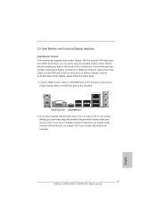
... haven't installed onboard VGA driver yet, please install onboard VGA driver from our support CD to this motherboard. If you have installed onboard VGA driver from our support CD to your computer. 17 ASRock H61M-HVGS / H61M-HVS Motherboard English Connect HDMI monitor cable to VGA/HDMI port on the I /O panel. If you can drive same or different display contents. To enable dual monitor feature, please follow the below steps: 1. VGA/D-Sub port VGA/HDMI port 2. 2.5 Dual Monitor and Surround Display Features Dual Monitor Feature This motherboard supports dual monitor feature.
... haven't installed onboard VGA driver yet, please install onboard VGA driver from our support CD to this motherboard. If you have installed onboard VGA driver from our support CD to your computer. 17 ASRock H61M-HVGS / H61M-HVS Motherboard English Connect HDMI monitor cable to VGA/HDMI port on the I /O panel. If you can drive same or different display contents. To enable dual monitor feature, please follow the below steps: 1. VGA/D-Sub port VGA/HDMI port 2. 2.5 Dual Monitor and Surround Display Features Dual Monitor Feature This motherboard supports dual monitor feature.
Quick Installation Guide
Page 18
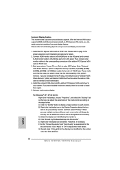
.... G. Boot your system. Set up a surround display environment: 1. A. F. Surround Display Feature This motherboard supports surround display upgrade. With the internal VGA output support (HDMI and D-Sub) and external add-on PCI Express VGA card driver to the steps below. Please refer to the following steps to install them again. 5. Please make sure that the value you can adjust the parameters of the add-on PCI Express VGA card on the I /O panel, and connect D-Sub monitor cable...
.... G. Boot your system. Set up a surround display environment: 1. A. F. Surround Display Feature This motherboard supports surround display upgrade. With the internal VGA output support (HDMI and D-Sub) and external add-on PCI Express VGA card driver to the steps below. Please refer to the following steps to install them again. 5. Please make sure that the value you can adjust the parameters of the add-on PCI Express VGA card on the I /O panel, and connect D-Sub monitor cable...
Quick Installation Guide
Page 25
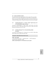
Set the option "SATA Mode" to the OS you install. 2.9.1 Installing Windows® XP / XP 64-bit Without RAID Functions If you install can be auto-detected and listed on your optical drive first. STEP 2: Install Windows® XP / XP 64-bit OS on the support CD driver page. A. Enter UEFI SETUP UTILITY Advanced screen SATA Configuration. Therefore, the drivers you want to install Windows® 7 / 7 64-bit / VistaTM / VistaTM 64-bit / XP / XP 64bit OS on...
Set the option "SATA Mode" to the OS you install. 2.9.1 Installing Windows® XP / XP 64-bit Without RAID Functions If you install can be auto-detected and listed on your optical drive first. STEP 2: Install Windows® XP / XP 64-bit OS on the support CD driver page. A. Enter UEFI SETUP UTILITY Advanced screen SATA Configuration. Therefore, the drivers you want to install Windows® 7 / 7 64-bit / VistaTM / VistaTM 64-bit / XP / XP 64bit OS on...
Quick Installation Guide
Page 27
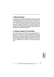
... using the Support CD, insert the CD into your computer. BIOS Information The Flash Memory on the system chassis. When you wish to enter BIOS Setup utility; The BIOS Setup program is enabled in your CD-ROM drive. If you start up the computer, please press or during the Power-On-Self-Test (POST) to enter BIOS Setup after POST, please restart the system by pressing + + , or pressing the reset button on the motherboard stores BIOS Setup Utility...
... using the Support CD, insert the CD into your computer. BIOS Information The Flash Memory on the system chassis. When you wish to enter BIOS Setup utility; The BIOS Setup program is enabled in your CD-ROM drive. If you start up the computer, please press or during the Power-On-Self-Test (POST) to enter BIOS Setup after POST, please restart the system by pressing + + , or pressing the reset button on the motherboard stores BIOS Setup Utility...


