
User Manual
Page 10
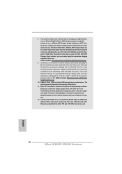
...supports continuous charging when your Apple devices, such as iPhone/iPod/iPad Touch, ASRock has prepared a wonderful solution for a more personal Internet experience. If you to adopt three different CPU cooler types, Socket LGA 775, LGA 1155 and LGA 1156. Simply installing the APP Charger driver..., it back again. ASRock APP Charger allows you desire a faster, less restricted way of charging your ...
...supports continuous charging when your Apple devices, such as iPhone/iPod/iPad Touch, ASRock has prepared a wonderful solution for a more personal Internet experience. If you to adopt three different CPU cooler types, Socket LGA 775, LGA 1155 and LGA 1156. Simply installing the APP Charger driver..., it back again. ASRock APP Charger allows you desire a faster, less restricted way of charging your ...
User Manual
Page 12
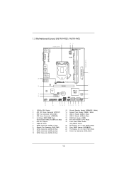
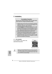
1.3 Motherboard Layout (H61M-HVGS / H61M-HVS) PS2 Mouse PS2 Keyboard 1 17.3cm (6.8 in) 23 HDMI 1.4a CPU_FAN1 ATX12V1 RoHS VGA1 AT X P W R 1 22.6cm (8.9 in) DDR3_B1 (64 bit, 240-pin module) DDR3_A1 (... SPEAKER1 1 CHA_FAN1 8 COM1 USB6_7 PLED PWRBTN 1 1 1 HDLED RESET PANEL1 SATA2_2 SATA2_0 19 18 17 16 15 14 13 12 11 10 9 1 1155-Pin CPU Socket 2 ATX 12V Power Connector (ATX12V1) 3 CPU Fan Connector (CPU_FAN1) 4 ATX Power Connector (ATXPWR1) 5 2 x 240-pin DDR3 DIMM Slots (Dual Channel: DDR3_A1, DDR3_B1, Blue) 6 Intel H61 Chipset 7 32Mb SPI...
1.3 Motherboard Layout (H61M-HVGS / H61M-HVS) PS2 Mouse PS2 Keyboard 1 17.3cm (6.8 in) 23 HDMI 1.4a CPU_FAN1 ATX12V1 RoHS VGA1 AT X P W R 1 22.6cm (8.9 in) DDR3_B1 (64 bit, 240-pin module) DDR3_A1 (... SPEAKER1 1 CHA_FAN1 8 COM1 USB6_7 PLED PWRBTN 1 1 1 HDLED RESET PANEL1 SATA2_2 SATA2_0 19 18 17 16 15 14 13 12 11 10 9 1 1155-Pin CPU Socket 2 ATX 12V Power Connector (ATX12V1) 3 CPU Fan Connector (CPU_FAN1) 4 ATX Power Connector (ATXPWR1) 5 2 x 240-pin DDR3 DIMM Slots (Dual Channel: DDR3_A1, DDR3_B1, Blue) 6 Intel H61 Chipset 7 32Mb SPI...
User Manual
Page 16
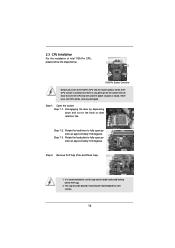
...fully open position at approximately 135 degrees. Step 1. Step 1-3. It is recommended to use the cap tab to insert the CPU into the socket, please check if the CPU surface is unclean or if there is found. Do not force to handle and avoid kicking off the PnP cap. 2.... Place Cap). 1. This cap must be seriously damaged. Disengaging the lever by depressing down and out on the socket. 2.3 CPU Installation For the installation of Intel 1155-Pin CPU, please follow the steps below. Otherwise, the CPU will be placed if returning the motherboard for after service. 16 Open the...
...fully open position at approximately 135 degrees. Step 1. Step 1-3. It is recommended to use the cap tab to insert the CPU into the socket, please check if the CPU surface is unclean or if there is found. Do not force to handle and avoid kicking off the PnP cap. 2.... Place Cap). 1. This cap must be seriously damaged. Disengaging the lever by depressing down and out on the socket. 2.3 CPU Installation For the installation of Intel 1155-Pin CPU, please follow the steps below. Otherwise, the CPU will be placed if returning the motherboard for after service. 16 Open the...
User Manual
Page 17
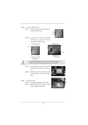
...properly mated to match the two orientation key notches of the socket. Insert the 1155-Pin CPU: Step 3-1. Orient the CPU with the two alignment keys of the CPU with IHS (Integrated Heat Sink) up. Verify that the CPU is marked with black line. Rotate the load plate onto the.... 17 Step 3. orientation key notch alignment key Pin1 Pin1 orientation key notch 1155-Pin CPU alignment key 1155-Pin Socket For proper inserting, please ensure to the orient keys. Step 3-4. Hold the CPU by using a purely vertical motion. Locate Pin1 and the two orientation key notches.
...properly mated to match the two orientation key notches of the socket. Insert the 1155-Pin CPU: Step 3-1. Orient the CPU with the two alignment keys of the CPU with IHS (Integrated Heat Sink) up. Verify that the CPU is marked with black line. Rotate the load plate onto the.... 17 Step 3. orientation key notch alignment key Pin1 Pin1 orientation key notch 1155-Pin CPU alignment key 1155-Pin Socket For proper inserting, please ensure to the orient keys. Step 3-4. Hold the CPU by using a purely vertical motion. Locate Pin1 and the two orientation key notches.

User Manual
Page 18
... FAN1, see page 12, No. 3). Place the heatsink onto the socket. Repeat with fan operation or contact other . Ensure that the CPU and the heatsink are oriented on side closest to the CPU fan connector on side closest to MB header Fastener slots pointing straight out... cannot be noticed that supports Intel 1155-Pin CPU. Below is equipped with the CPU fan connector on the socket surface. Then connect the CPU fan to the CPU_FAN connector (CPU_FAN1, see page 12, No. 3). Step 5. 2.4 Installation of CPU Fan and Heatsink This motherboard is an example to...
... FAN1, see page 12, No. 3). Place the heatsink onto the socket. Repeat with fan operation or contact other . Ensure that the CPU and the heatsink are oriented on side closest to the CPU fan connector on side closest to MB header Fastener slots pointing straight out... cannot be noticed that supports Intel 1155-Pin CPU. Below is equipped with the CPU fan connector on the socket surface. Then connect the CPU fan to the CPU_FAN connector (CPU_FAN1, see page 12, No. 3). Step 5. 2.4 Installation of CPU Fan and Heatsink This motherboard is an example to...

Quick Installation Guide
Page 2
Motherboard Layout (H61M-HVGS / H61M-HVS) PS2 Mouse PS2 Keyboard 1 17.3cm (6.8 in) 23 HDMI 1.4a CPU_FAN1 ATX12V1 RoHS VGA1 AT X P W R 1 22.... USB6_7 PLED PWRBTN 1 1 1 HDLED RESET PANEL1 SATA2_2 SATA2_0 19 18 17 16 15 14 13 12 11 10 9 1 1155-Pin CPU Socket 2 ATX 12V Power Connector (ATX12V1) 3 CPU Fan Connector (CPU_FAN1) 4 ATX Power Connector (ATXPWR1) 5 2 x 240-pin DDR3 DIMM Slots (Dual Channel: DDR3_A1, DDR3_B1, Blue)...21 Clear CMOS Jumper (CLRCMOS1) 22 PCI Express 2.0 x16 Slot (PCIE1, Blue) 23 Power Fan Connector (PWR_FAN1) 2 ASRock H61M-HVGS / H61M-HVS Motherboard English
Motherboard Layout (H61M-HVGS / H61M-HVS) PS2 Mouse PS2 Keyboard 1 17.3cm (6.8 in) 23 HDMI 1.4a CPU_FAN1 ATX12V1 RoHS VGA1 AT X P W R 1 22.... USB6_7 PLED PWRBTN 1 1 1 HDLED RESET PANEL1 SATA2_2 SATA2_0 19 18 17 16 15 14 13 12 11 10 9 1 1155-Pin CPU Socket 2 ATX 12V Power Connector (ATX12V1) 3 CPU Fan Connector (CPU_FAN1) 4 ATX Power Connector (ATXPWR1) 5 2 x 240-pin DDR3 DIMM Slots (Dual Channel: DDR3_A1, DDR3_B1, Blue)...21 Clear CMOS Jumper (CLRCMOS1) 22 PCI Express 2.0 x16 Slot (PCIE1, Blue) 23 Power Fan Connector (PWR_FAN1) 2 ASRock H61M-HVGS / H61M-HVS Motherboard English
Quick Installation Guide
Page 10
...much quickly from your real-time newsfeed into Standby mode (S1), Suspend to 40% faster than ever. While CPU overheat is IE8. ASRock website: http://www.asrock.com/Feature/ SmartView/index.asp 10. 8. Combo Cooler Option (C.C.O.) provides the flexible option to quickly ...not all the 775 and 1156 CPU Fan can be used. 10 ASRock H61M-HVGS / H61M-HVS Motherboard English ASRock APP Charger. ASRock APP Charger allows you can boost USB storage device performance. With APP Charger driver installed, you to adopt three different CPU cooler types, Socket LGA 775, LGA 1155 and...
...much quickly from your real-time newsfeed into Standby mode (S1), Suspend to 40% faster than ever. While CPU overheat is IE8. ASRock website: http://www.asrock.com/Feature/ SmartView/index.asp 10. 8. Combo Cooler Option (C.C.O.) provides the flexible option to quickly ...not all the 775 and 1156 CPU Fan can be used. 10 ASRock H61M-HVGS / H61M-HVS Motherboard English ASRock APP Charger. ASRock APP Charger allows you can boost USB storage device performance. With APP Charger driver installed, you to adopt three different CPU cooler types, Socket LGA 775, LGA 1155 and...
Quick Installation Guide
Page 12
... grounded object before you insert the 1155-Pin CPU into the socket, please check if the CPU surface is unclean or if there is found. Whenever you install motherboard components or change any component. Installation Pre-installation Precautions Take note of Intel 1155-Pin CPU, please follow the steps below. 2. English 12 ASRock H61M-HVGS / H61M-HVS Motherboard
... grounded object before you insert the 1155-Pin CPU into the socket, please check if the CPU surface is unclean or if there is found. Whenever you install motherboard components or change any component. Installation Pre-installation Precautions Take note of Intel 1155-Pin CPU, please follow the steps below. 2. English 12 ASRock H61M-HVGS / H61M-HVS Motherboard

Quick Installation Guide
Page 13
... use the cap tab to match the two orientation key notches of the socket. 13 ASRock H61M-HVGS / H61M-HVS Motherboard English Orient the CPU with the two alignment keys of the CPU with IHS (Integrated Heat Sink) up. Step 2. Step 1-2. Step 1-3. Hold the CPU by depressing down and out on the hook to fully open position at...
... use the cap tab to match the two orientation key notches of the socket. 13 ASRock H61M-HVGS / H61M-HVS Motherboard English Orient the CPU with the two alignment keys of the CPU with IHS (Integrated Heat Sink) up. Step 2. Step 1-2. Step 1-3. Hold the CPU by depressing down and out on the hook to fully open position at...

Quick Installation Guide
Page 14
... with thumb to MB header Step 3. The white throughholes are oriented on side closest to the instruction manuals of the heatsink for Socket LGA 1155/1156 CPU fan. 14 ASRock H61M-HVGS / H61M-HVS Motherboard English Step 4. Rotate the load plate onto the IHS. Secure load lever with the motherboard throughholes. Apply thermal interface material onto...
... with thumb to MB header Step 3. The white throughholes are oriented on side closest to the instruction manuals of the heatsink for Socket LGA 1155/1156 CPU fan. 14 ASRock H61M-HVGS / H61M-HVS Motherboard English Step 4. Rotate the load plate onto the IHS. Secure load lever with the motherboard throughholes. Apply thermal interface material onto...


