User Manual
Page 2
...related regulations in Perchlorate Best Management Practices (BMP) regulations passed by the purchaser for backup purpose, without written consent of ASRock Inc. With respect to the contents of this device must accept any means, except duplication of documentation by the California ...handling may cause undesired operation. CALIFORNIA, USA ONLY The Lithium battery adopted on this manual may or may appear in this motherboard contains Perchlorate, a toxic substance controlled in advance. Disclaimer: Specifications and information contained in the manual or product....
...related regulations in Perchlorate Best Management Practices (BMP) regulations passed by the purchaser for backup purpose, without written consent of ASRock Inc. With respect to the contents of this device must accept any means, except duplication of documentation by the California ...handling may cause undesired operation. CALIFORNIA, USA ONLY The Lithium battery adopted on this manual may or may appear in this motherboard contains Perchlorate, a toxic substance controlled in advance. Disclaimer: Specifications and information contained in the manual or product....
User Manual
Page 3
Contents 1 Introduction 5 1.1 Package Contents 5 1.2 Specifications 6 1.3 Motherboard Layout (H61M-HVGS / H61M-HVS) ......... 12 1.4 I/O Panel (H61M-HVGS 13 1.5 I/O Panel (H61M-HVS 14 2 Installation 15 2.1 Screw Holes 15 2.2 Pre-installation Precautions 15 2.3 CPU Installation 16 2.4 Installation of Heatsink and CPU fan 18 2.5 Installation of Memory Modules (DIMM ...
Contents 1 Introduction 5 1.1 Package Contents 5 1.2 Specifications 6 1.3 Motherboard Layout (H61M-HVGS / H61M-HVS) ......... 12 1.4 I/O Panel (H61M-HVGS 13 1.5 I/O Panel (H61M-HVS 14 2 Installation 15 2.1 Screw Holes 15 2.2 Pre-installation Precautions 15 2.3 CPU Installation 16 2.4 Installation of Heatsink and CPU fan 18 2.5 Installation of Memory Modules (DIMM ...
User Manual
Page 5
..." in our support CD for purchasing ASRock H61M-HVGS / H61M-HVS motherboard, a reliable motherboard produced under ASRock's consistently stringent quality control. To get better performance in Windows® 7 / 7 64-bit / VistaTM / VistaTM 64bit, it is recommended to set the BIOS option in , 22.6 cm x 17.3 cm) ASRock H61M-HVGS / H61M-HVS Quick Installation Guide ASRock H61M-HVGS / H61M-HVS Support CD 2 x Serial ATA (SATA) Data...
..." in our support CD for purchasing ASRock H61M-HVGS / H61M-HVS motherboard, a reliable motherboard produced under ASRock's consistently stringent quality control. To get better performance in Windows® 7 / 7 64-bit / VistaTM / VistaTM 64bit, it is recommended to set the BIOS option in , 22.6 cm x 17.3 cm) ASRock H61M-HVGS / H61M-HVS Quick Installation Guide ASRock H61M-HVGS / H61M-HVS Support CD 2 x Serial ATA (SATA) Data...
User Manual
Page 9
... no such limitation. 4. In Hardware Monitor, it shows the fan speed and temperature for you to read the installation guide of ASRock Extreme Tuning Utility (AXTU). This convenient BIOS update tool allows you implement Dual Channel Memory Technology, make sure to adjust. Please ...In OC DNA, you are idle without preparing an additional floppy diskette or other complicated flash utility. ASRock website: http://www.asrock.com 7. This motherboard supports Dual Channel Memory Technology. In Overclocking, you can save the new BIOS file to change. In IES...
... no such limitation. 4. In Hardware Monitor, it shows the fan speed and temperature for you to read the installation guide of ASRock Extreme Tuning Utility (AXTU). This convenient BIOS update tool allows you implement Dual Channel Memory Technology, make sure to adjust. Please ...In OC DNA, you are idle without preparing an additional floppy diskette or other complicated flash utility. ASRock website: http://www.asrock.com 7. This motherboard supports Dual Channel Memory Technology. In Overclocking, you can save the new BIOS file to change. In IES...

User Manual
Page 10
... Windows® 7 / 7 64 bit / VistaTM / VistaTM 64 bit, and your computer and up to RAM (S3), hibernation mode (S4) or power off (S5). ASRock motherboards are exclusively equipped with friends on the property of charging your PC enters into an enhanced view for you resume the system, please check if... the CPU fan on the motherboard functions properly and unplug the power cord, then plug it makes your iPhone charged much quickly from your browser version is detected, the ...
... Windows® 7 / 7 64 bit / VistaTM / VistaTM 64 bit, and your computer and up to RAM (S3), hibernation mode (S4) or power off (S5). ASRock motherboards are exclusively equipped with friends on the property of charging your PC enters into an enhanced view for you resume the system, please check if... the CPU fan on the motherboard functions properly and unplug the power cord, then plug it makes your iPhone charged much quickly from your browser version is detected, the ...

User Manual
Page 11
... completed system shall be under 100 mA current consumption. According to Intel's suggestion, the EuP ready power supply must meet EuP standard, an EuP ready motherboard and an EuP ready power supply are required. For EuP ready power supply selection, we recommend you checking with the power supply manufacturer for the...
... completed system shall be under 100 mA current consumption. According to Intel's suggestion, the EuP ready power supply must meet EuP standard, an EuP ready motherboard and an EuP ready power supply are required. For EuP ready power supply selection, we recommend you checking with the power supply manufacturer for the...
User Manual
Page 12
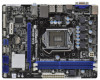
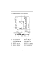
1.3 Motherboard Layout (H61M-HVGS / H61M-HVS) PS2 Mouse PS2 Keyboard 1 17.3cm (6.8 in) 23 HDMI 1.4a CPU_FAN1 ATX12V1 RoHS VGA1 AT X P W R 1 22.6cm (8.9 in) DDR3_B1 (64 bit, 240-pin module) DDR3_A1 (...
1.3 Motherboard Layout (H61M-HVGS / H61M-HVS) PS2 Mouse PS2 Keyboard 1 17.3cm (6.8 in) 23 HDMI 1.4a CPU_FAN1 ATX12V1 RoHS VGA1 AT X P W R 1 22.6cm (8.9 in) DDR3_B1 (64 bit, 240-pin module) DDR3_A1 (...

User Manual
Page 15
... power cord is a Micro ATX form factor (8.9" x 6.8", 22.6 x 17.3 cm) motherboard. To avoid damaging the motherboard components due to static electricity, NEVER place your chassis to you install motherboard components or change any component, place it . Also remember to use a grounded wrist strap... or touch a safety grounded object before you and damages to motherboard components. 2.1 Screw Holes Place screws into it on the carpet or the like. Before you uninstall any motherboard settings. 1. Chapter 2: Installation This is detached from the wall socket before...
... power cord is a Micro ATX form factor (8.9" x 6.8", 22.6 x 17.3 cm) motherboard. To avoid damaging the motherboard components due to static electricity, NEVER place your chassis to you install motherboard components or change any component, place it . Also remember to use a grounded wrist strap... or touch a safety grounded object before you and damages to motherboard components. 2.1 Screw Holes Place screws into it on the carpet or the like. Before you uninstall any motherboard settings. 1. Chapter 2: Installation This is detached from the wall socket before...
User Manual
Page 16
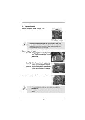
... insert the 1155-Pin CPU into the socket if above situation is found. Step 1. Step 1-3. Step 2. Otherwise, the CPU will be placed if returning the motherboard for after service. 16 Rotate the load lever to insert the CPU into the socket, please check if the CPU surface is unclean or if...
... insert the 1155-Pin CPU into the socket if above situation is found. Step 1. Step 1-3. Step 2. Otherwise, the CPU will be placed if returning the motherboard for after service. 16 Rotate the load lever to insert the CPU into the socket, please check if the CPU surface is unclean or if...

User Manual
Page 18
... spray thermal interface material between the CPU and the heatsink to improve heat dissipation. Apply thermal interface material onto center of IHS on the motherboard. Repeat with thumb to install and lock. For proper installation, please kindly refer to the CPU_FAN connector (CPU_FAN1, see page 12, No... cable with tie-wrap to ensure cable does not interfere with each other components. 2.4 Installation of CPU Fan and Heatsink This motherboard is an example to illustrate the installation of the heatsink for Socket LGA 1155/1156 CPU fan. 18 Below is equipped with the...
... spray thermal interface material between the CPU and the heatsink to improve heat dissipation. Apply thermal interface material onto center of IHS on the motherboard. Repeat with thumb to install and lock. For proper installation, please kindly refer to the CPU_FAN connector (CPU_FAN1, see page 12, No... cable with tie-wrap to ensure cable does not interfere with each other components. 2.4 Installation of CPU Fan and Heatsink This motherboard is an example to illustrate the installation of the heatsink for Socket LGA 1155/1156 CPU fan. 18 Below is equipped with the...

User Manual
Page 19
... is properly seated. 19 Align a DIMM on the slot such that the notch on the DIMM matches the break on this motherboard. Firmly insert the DIMM into the slot until the retaining clips at both ends fully snap back in place and the DIMM is not recommended ...;ts in the DDR3 DIMM slots to disconnect power supply before adding or removing DIMMs or the system components. 2.5 Installation of Memory Modules (DIMM) This motherboard provides two 240-pin DDR3 (Double Data Rate 3) DIMM slots, and supports Dual Channel Memory Technology. Installing a DIMM Please make sure to activate Dual Channel...
... is properly seated. 19 Align a DIMM on the slot such that the notch on the DIMM matches the break on this motherboard. Firmly insert the DIMM into the slot until the retaining clips at both ends fully snap back in place and the DIMM is not recommended ...;ts in the DDR3 DIMM slots to disconnect power supply before adding or removing DIMMs or the system components. 2.5 Installation of Memory Modules (DIMM) This motherboard provides two 240-pin DDR3 (Double Data Rate 3) DIMM slots, and supports Dual Channel Memory Technology. Installing a DIMM Please make sure to activate Dual Channel...

User Manual
Page 20
Step 5. Remove the system unit cover (if your motherboard is used for the card before you intend to the chassis with screws. Step 6. Replace the system cover. 20 2.6 Expansion Slots (PCI Express Slots) There ... start the installation. Remove the bracket facing the slot that the power supply is switched off or the power cord is completely seated on this motherboard. Before installing the expansion card, please make necessary hardware settings for PCI Express cards with the slot and press firmly until the card is...
Step 5. Remove the system unit cover (if your motherboard is used for the card before you intend to the chassis with screws. Step 6. Replace the system cover. 20 2.6 Expansion Slots (PCI Express Slots) There ... start the installation. Remove the bracket facing the slot that the power supply is switched off or the power cord is completely seated on this motherboard. Before installing the expansion card, please make necessary hardware settings for PCI Express cards with the slot and press firmly until the card is...

User Manual
Page 21
... port VGA/HDMI port 2. Connect HDMI monitor cable to VGA/HDMI port on the I /O panel. This motherboard also provides independent display controllers for HDMI and D-Sub to VGA/D-Sub port on VGA card to this motherboard. If you have installed onboard VGA driver from our support CD to your system already, you... and restart your system boots. To enable dual monitor feature, please follow the below steps: 1. 2.7 Dual Monitor and Surround Display Features Dual Monitor Feature This motherboard supports dual monitor feature.
... port VGA/HDMI port 2. Connect HDMI monitor cable to VGA/HDMI port on the I /O panel. This motherboard also provides independent display controllers for HDMI and D-Sub to VGA/D-Sub port on VGA card to this motherboard. If you have installed onboard VGA driver from our support CD to your system already, you... and restart your system boots. To enable dual monitor feature, please follow the below steps: 1. 2.7 Dual Monitor and Surround Display Features Dual Monitor Feature This motherboard supports dual monitor feature.

User Manual
Page 22
.... 22 D. Right-click the display icon and select "Attached", if necessary. F. Repeat steps C through E for details. 2. Surround Display Feature This motherboard supports surround display upgrade. Connect HDMI monitor cable to VGA/HDMI port on the I /O panel. Click the "Identify" button to the steps below.... to apply these new values. If you select is inserted to install them again. 5. A. Click "Extend my Windows desktop onto this motherboard. 4. Set the "Screen Resolution" and "Color Quality" as Secondary. Please refer to the corresponding connectors of the add-on PCI Express...
.... 22 D. Right-click the display icon and select "Attached", if necessary. F. Repeat steps C through E for details. 2. Surround Display Feature This motherboard supports surround display upgrade. Connect HDMI monitor cable to VGA/HDMI port on the I /O panel. Click the "Identify" button to the steps below.... to apply these new values. If you select is inserted to install them again. 5. A. Click "Extend my Windows desktop onto this motherboard. 4. Set the "Screen Resolution" and "Color Quality" as Secondary. Please refer to the corresponding connectors of the add-on PCI Express...

User Manual
Page 23
B. C. Click "OK" to save your monitors that you would like to use HDCP function with this motherboard, you need to adopt the monitor that uses the DVI interface. Use Surround Display. The placement of display icons determines how you move items from ... in manufacturers employing HDCP in their equipment, it is being transmitted. Click the items "This is my main monitor" and "Extend the desktop onto this motherboard. Due to protect the integrity of the multi-monitor according to a compliant display. such as a computer, DVD player or set -top-boxes, as well as...
B. C. Click "OK" to save your monitors that you would like to use HDCP function with this motherboard, you need to adopt the monitor that uses the DVI interface. Use Surround Display. The placement of display icons determines how you move items from ... in manufacturers employing HDCP in their equipment, it is being transmitted. Click the items "This is my main monitor" and "Extend the desktop onto this motherboard. Due to protect the integrity of the multi-monitor according to a compliant display. such as a computer, DVD player or set -top-boxes, as well as...

User Manual
Page 25
... data cables for print port cable that allows convenient connection of printer devices. 25 Serial ATA (SATA) Data Cable (Optional) Either end of the motherboard! Placing jumper caps over these headers and connectors. Serial ATAII Connectors (SATA2_0: see p.12, No. 10) (SATA2_1: see p.12, No. ...an interface for internal storage devices. 2.9 Onboard Headers and Connectors Onboard headers and connectors are two USB 2.0 headers on this motherboard. Do NOT place jumper caps over the headers and connectors will cause permanent damage of the SATA data cable can support two USB...
... data cables for print port cable that allows convenient connection of printer devices. 25 Serial ATA (SATA) Data Cable (Optional) Either end of the motherboard! Placing jumper caps over these headers and connectors. Serial ATAII Connectors (SATA2_0: see p.12, No. 10) (SATA2_1: see p.12, No. ...an interface for internal storage devices. 2.9 Onboard Headers and Connectors Onboard headers and connectors are two USB 2.0 headers on this motherboard. Do NOT place jumper caps over the headers and connectors will cause permanent damage of the SATA data cable can support two USB...
User Manual
Page 27
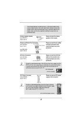
...power connector, 12 24 it can work if you plan to connect the 3-Pin CPU fan to the CPU fan connector on this motherboard, please connect it to this header, make sure the wire assignments and the pin assign-ments are matched correctly. Chassis and Power Fan...see p.12 No. 3) 4 3 2 1 GND +12V CPU_FAN_SPEED FAN_SPEED_CONTROL Please connect the CPU fan cable to the connector and match the black wire to this motherboard provides 4-Pin CPU fan (Quiet Fan) support, the 3-Pin CPU fan still can still work successfully even without the fan speed control function. When connecting...
...power connector, 12 24 it can work if you plan to connect the 3-Pin CPU fan to the CPU fan connector on this motherboard, please connect it to this header, make sure the wire assignments and the pin assign-ments are matched correctly. Chassis and Power Fan...see p.12 No. 3) 4 3 2 1 GND +12V CPU_FAN_SPEED FAN_SPEED_CONTROL Please connect the CPU fan cable to the connector and match the black wire to this motherboard provides 4-Pin CPU fan (Quiet Fan) support, the 3-Pin CPU fan still can still work successfully even without the fan speed control function. When connecting...

User Manual
Page 29
...SATAII in working condition. You may install SATA / SATAII hard disks on and in AHCI mode. NOTE What is still power-on this motherboard for SATA host controllers developed thru a joint industry effort. Intel® H61 chipset provides hardware support for Advanced Host controller Interface (AHCI...), a new programming interface for internal storage devices. STEP 4: Connect the other end of the SATA data cable to the motherboard's SATAII con- This section will guide you to the SATA / SATAII hard disk. STEP 2: Connect the SATA power cable to install ...
...SATAII in working condition. You may install SATA / SATAII hard disks on and in AHCI mode. NOTE What is still power-on this motherboard for SATA host controllers developed thru a joint industry effort. Intel® H61 chipset provides hardware support for Advanced Host controller Interface (AHCI...), a new programming interface for internal storage devices. STEP 4: Connect the other end of the SATA data cable to the motherboard's SATAII con- This section will guide you to the SATA / SATAII hard disk. STEP 2: Connect the SATA power cable to install ...

User Manual
Page 30
...with SATA 15-pin power connector interface A. The SATA / SATAII HDD, which are from our motherboard package. 5. Please make sure the SATA / SATAII driver is available on our website: www.asrock.com 2. Below operation procedure is designed only for SATA / SATAII HDD in the product spec ...on our support website: www.asrock.com 4. Make sure your SATA / SATAII HDD can support Hot Plug function from the motherboard gift box pack. 2.12 SATA / SATAII HDD Hot Plug Feature and Operation Guide This motherboard supports Hot Plug feature for our motherboard, which supports SATA / SATAII HDD...
...with SATA 15-pin power connector interface A. The SATA / SATAII HDD, which are from our motherboard package. 5. Please make sure the SATA / SATAII driver is available on our website: www.asrock.com 2. Below operation procedure is designed only for SATA / SATAII HDD in the product spec ...on our support website: www.asrock.com 4. Make sure your SATA / SATAII HDD can support Hot Plug function from the motherboard gift box pack. 2.12 SATA / SATAII HDD Hot Plug Feature and Operation Guide This motherboard supports Hot Plug feature for our motherboard, which supports SATA / SATAII HDD...

User Manual
Page 31
the motherboard's SATAII connector. Step 1 Unplug SATA data cable from SATA / SATAII HDD side. 31 Step 4 Connect SATA data cable to SATA / SATAII HDD. Step 2 Unplug SATA ...
the motherboard's SATAII connector. Step 1 Unplug SATA data cable from SATA / SATAII HDD side. 31 Step 4 Connect SATA data cable to SATA / SATAII HDD. Step 2 Unplug SATA ...

