
User Manual
Page 1
All rights reserved. 1 H55DE3 User Manual Version 1.1 Published March 2010 Copyright©2010 ASRock INC.
All rights reserved. 1 H55DE3 User Manual Version 1.1 Published March 2010 Copyright©2010 ASRock INC.

User Manual
Page 2
Disclaimer: Specifications and information contained in this manual, ASRock does not provide warranty of any kind, either expressed or implied, including but not limited to the implied warranties or conditions of merchantability or fitness ... or may not cause harmful interference, and (2) this motherboard contains Perchlorate, a toxic substance controlled in the manual or product. ASRock assumes no event shall ASRock, its directors, officers, employees, or agents be reproduced, transcribed, transmitted, or translated in any language, in any form or by any means, except duplication of ...
Disclaimer: Specifications and information contained in this manual, ASRock does not provide warranty of any kind, either expressed or implied, including but not limited to the implied warranties or conditions of merchantability or fitness ... or may not cause harmful interference, and (2) this motherboard contains Perchlorate, a toxic substance controlled in the manual or product. ASRock assumes no event shall ASRock, its directors, officers, employees, or agents be reproduced, transcribed, transmitted, or translated in any language, in any form or by any means, except duplication of ...
User Manual
Page 5
... (ATX Form Factor: 12.0-in x 8.3-in, 30.5 cm x 21.1 cm) ASRock H55DE3 Quick Installation Guide ASRock H55DE3 Support CD 2 x Serial ATA (SATA) Data Cables (Optional) 1 x I/O Panel Shield 5 It delivers excellent performance with robust design conforming to ASRock's commitment to BIOS setup and information of this manual will be subject to the hardware installation. You may find...
... (ATX Form Factor: 12.0-in x 8.3-in, 30.5 cm x 21.1 cm) ASRock H55DE3 Quick Installation Guide ASRock H55DE3 Support CD 2 x Serial ATA (SATA) Data Cables (Optional) 1 x I/O Panel Shield 5 It delivers excellent performance with robust design conforming to ASRock's commitment to BIOS setup and information of this manual will be subject to the hardware installation. You may find...
User Manual
Page 18
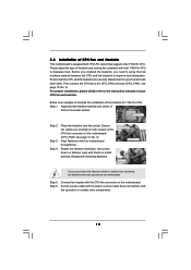
... the heatsink, you press down on fastener caps with the CPU fan connector on the motherboard. For proper installation, please kindly refer to the instruction manuals of CPU Fan and Heatsink This motherboard is an example to illustrate the installation of heatsink and cooling fan compliant with 1156-Pin socket that...
... the heatsink, you press down on fastener caps with the CPU fan connector on the motherboard. For proper installation, please kindly refer to the instruction manuals of CPU Fan and Heatsink This motherboard is an example to illustrate the installation of heatsink and cooling fan compliant with 1156-Pin socket that...

User Manual
Page 22
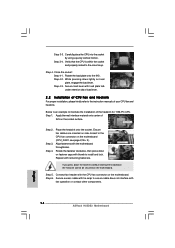
... combining multiple high performance Graphics Processing Units (GPU) in the future, please refer to PCIE4 slot. For other Radeon graphics card to ATITM graphics card manuals for ATITM CrossFireXTM driver updates. 1. Insert one Radeon graphics card into PCIE2 slot and the other CrossFireXTM cards that the cards are supported with intelligent...
... combining multiple high performance Graphics Processing Units (GPU) in the future, please refer to PCIE4 slot. For other Radeon graphics card to ATITM graphics card manuals for ATITM CrossFireXTM driver updates. 1. Insert one Radeon graphics card into PCIE2 slot and the other CrossFireXTM cards that the cards are supported with intelligent...

User Manual
Page 28
... security, protects digital identities, and ensures platform integrity. You don't need to function correctly. Enter BIOS Setup Utility. Please follow the instruction in our manual and chassis manual to OUT2_L. TPM Header (19-pin TPM1) (see p.12 No. 22) 1 PCICLK FRAME PCIRST# LAD3 +3V LAD0 NC +3VSB GND PWRDWN GND NC LAD2...
... security, protects digital identities, and ensures platform integrity. You don't need to function correctly. Enter BIOS Setup Utility. Please follow the instruction in our manual and chassis manual to OUT2_L. TPM Header (19-pin TPM1) (see p.12 No. 22) 1 PCICLK FRAME PCIRST# LAD3 +3V LAD0 NC +3VSB GND PWRDWN GND NC LAD2...

User Manual
Page 31
... Please do not connect the white end of HDMI_SPDIF cable to the wrong connector of HDMI VGA card vendor. Please refer to the user manual of HDMI_SPDIF cable to the HDMI_SPDIF header (HDMI_SPDIF1, yellow, see page 12, No. 25) on HDMI_SPDIF cable. Step 5. Otherwise, the...the HDMI_SPDIF connector of HDMI_SPDIF header and HDMI_SPDIF cable connectors, please refer to page 30. Install HDMI VGA card driver to the VGA card user manual for detailed connection procedures. white end (2-pin) (B) white end (3-pin) (C) Step 4. For example, this motherboard and the HDMI VGA card...
... Please do not connect the white end of HDMI_SPDIF cable to the wrong connector of HDMI VGA card vendor. Please refer to the user manual of HDMI_SPDIF cable to the HDMI_SPDIF header (HDMI_SPDIF1, yellow, see page 12, No. 25) on HDMI_SPDIF cable. Step 5. Otherwise, the...the HDMI_SPDIF connector of HDMI_SPDIF header and HDMI_SPDIF cable connectors, please refer to page 30. Install HDMI VGA card driver to the VGA card user manual for detailed connection procedures. white end (2-pin) (B) white end (3-pin) (C) Step 4. For example, this motherboard and the HDMI VGA card...

User Manual
Page 34
.... 3. SATA power cable with SATA 15-pin power connector interface A. The latest SATA / SATAII driver is available on our website: www.asrock.com 2. Please read below instructions step by the chipset because of its limitation, the SATA / SATAII Hot Plug support information of HDD crash... 1x4-pin conventional power connector (White) connect to use the SATA power cable & data cable, which are from your dealer or HDD user manual. Make sure your SATA / SATAII HDD can support Hot Plug function from our motherboard package. 5. Please follow below operation guide of attention, ...
.... 3. SATA power cable with SATA 15-pin power connector interface A. The latest SATA / SATAII driver is available on our website: www.asrock.com 2. Please read below instructions step by the chipset because of its limitation, the SATA / SATAII Hot Plug support information of HDD crash... 1x4-pin conventional power connector (White) connect to use the SATA power cable & data cable, which are from your dealer or HDD user manual. Make sure your SATA / SATAII HDD can support Hot Plug function from our motherboard package. 5. Please follow below operation guide of attention, ...

User Manual
Page 37
... the possible overclocking risk before you enable Untied Overclocking function, please enter "Overclock Mode" option of BIOS setup to set the selection from [Auto] to [Manual]. Using SATA / SATAII HDDs without NCQ function STEP 1: Set up BIOS. Enter BIOS SETUP UTILITY Advanced screen Storage Configuration. Before you apply Untied Overclocking Technology...
... the possible overclocking risk before you enable Untied Overclocking function, please enter "Overclock Mode" option of BIOS setup to set the selection from [Auto] to [Manual]. Using SATA / SATAII HDDs without NCQ function STEP 1: Set up BIOS. Enter BIOS SETUP UTILITY Advanced screen Storage Configuration. Before you apply Untied Overclocking Technology...

User Manual
Page 40
... your CPU and motherboard. Load XMP Setting You can use this option to load memory EZ overclocking setting. If you select [Manual], Untied Overclocking function is a revolutionary technology that delivers unparalleled power savings. Load CPU EZ OC Setting You can use this function...note that overclocing may cause damage to your memory and motherboard. Intelligent Energy Saver Intelligent Energy Saver is enabled. Configuration options: [Auto], [Manual], [I.O.T.] and [Optimized]. Please refer to Sub Screen F1 General Help F9 Load Defaults F10 Save and Exit ESC Exit v02.54 (C)...
... your CPU and motherboard. Load XMP Setting You can use this option to load memory EZ overclocking setting. If you select [Manual], Untied Overclocking function is a revolutionary technology that delivers unparalleled power savings. Load CPU EZ OC Setting You can use this function...note that overclocing may cause damage to your memory and motherboard. Intelligent Energy Saver Intelligent Energy Saver is enabled. Configuration options: [Auto], [Manual], [I.O.T.] and [Optimized]. Please refer to Sub Screen F1 General Help F9 Load Defaults F10 Save and Exit ESC Exit v02.54 (C)...

User Manual
Page 43
...05V], [1.15V] and [1.25V]. Configuration options: [Auto], [+0 mV] to select CPU GFX offset Voltage. The default value is [Auto]. Configuration options: [Auto], [Manual] and [Overdrive Offset]. The default value is [Auto]. CPU GFX Offset Voltage Use this to [+300 mV]. In this option, you like to select CPU... PLL Voltage. Configuration options: [Auto], [1.81V], [1.94V], [2.06V] and [2.18V]. ASRock VDrop Control Use this to your own requirements. 43 The default value is [Auto]. The default value is [Auto]. CPU PLL Voltage Use this to...
...05V], [1.15V] and [1.25V]. Configuration options: [Auto], [+0 mV] to select CPU GFX offset Voltage. The default value is [Auto]. Configuration options: [Auto], [Manual] and [Overdrive Offset]. The default value is [Auto]. CPU GFX Offset Voltage Use this to [+300 mV]. In this option, you like to select CPU... PLL Voltage. Configuration options: [Auto], [1.81V], [1.94V], [2.06V] and [2.18V]. ASRock VDrop Control Use this to your own requirements. 43 The default value is [Auto]. The default value is [Auto]. CPU PLL Voltage Use this to...

Quick Installation Guide
Page 5
... the Support CD. In case any modifications of the motherboard can be found in the user manual presented in , 30.5 cm x 21.1 cm) ASRock H55DE3 Quick Installation Guide ASRock H55DE3 Support CD 2 x Serial ATA (SATA) Data Cables (Optional) 1 x I/O Panel Shield 5 ASRock H55DE3 Motherboard English This Quick Installation Guide contains introduction of this motherboard, please visit our website...
... the Support CD. In case any modifications of the motherboard can be found in the user manual presented in , 30.5 cm x 21.1 cm) ASRock H55DE3 Quick Installation Guide ASRock H55DE3 Support CD 2 x Serial ATA (SATA) Data Cables (Optional) 1 x I/O Panel Shield 5 ASRock H55DE3 Motherboard English This Quick Installation Guide contains introduction of this motherboard, please visit our website...

Quick Installation Guide
Page 9
...VistaTM 64-bit / VistaTM. 10. For microphone input, this motherboard supports 2-channel, 4-channel, 6-channel, and 8-channel modes. ASRock website: http://www.asrock.com/feature/OCTuner/index.htm 9 ASRock H55DE3 Motherboard English About the setting of "Hyper Threading Technology", please check page 45 of the three monitors only. Before you to... size may be less than 4GB for the reservation for the operation procedures of memory modules on page 32 of "User Manual" in EDID. D-Sub, DVI-D and HDMI monitors cannot be enabled only if the display supports 12bpc in the support CD...
...VistaTM 64-bit / VistaTM. 10. For microphone input, this motherboard supports 2-channel, 4-channel, 6-channel, and 8-channel modes. ASRock website: http://www.asrock.com/feature/OCTuner/index.htm 9 ASRock H55DE3 Motherboard English About the setting of "Hyper Threading Technology", please check page 45 of the three monitors only. Before you to... size may be less than 4GB for the reservation for the operation procedures of memory modules on page 32 of "User Manual" in EDID. D-Sub, DVI-D and HDMI monitors cannot be enabled only if the display supports 12bpc in the support CD...
Quick Installation Guide
Page 14
... be secured on the motherboard. Connect fan header with thumb to ensure cable does not interfere with the motherboard throughholes. English 14 ASRock H55DE3 Motherboard While pressing down on load plate, engage the load lever. Step 1. Align fasteners with fan operation or contact other components....installation of the heatsink for 1156-Pin CPU. Step 2. Step 3. Step 4. Ensure fan cables are oriented on side closest to the instruction manuals of IHS on the motherboard (CPU_FAN1, see page 2, No. 3). Repeat with load plate tab under retention tab of load lever. 2.2 ...
... be secured on the motherboard. Connect fan header with thumb to ensure cable does not interfere with the motherboard throughholes. English 14 ASRock H55DE3 Motherboard While pressing down on load plate, engage the load lever. Step 1. Align fasteners with fan operation or contact other components....installation of the heatsink for 1156-Pin CPU. Step 2. Step 3. Step 4. Ensure fan cables are oriented on side closest to the instruction manuals of IHS on the motherboard (CPU_FAN1, see page 2, No. 3). Repeat with load plate tab under retention tab of load lever. 2.2 ...

Quick Installation Guide
Page 18
...combining multiple high performance Graphics Processing Units (GPU) in CrossFireXTM mode. 2.5.1 Graphics Cards Setup Different CrossFireXTM cards may require different methods to ATITM graphics card manuals for ATITM CrossFireXTM driver updates. 1. Please check AMD website for detailed installation guide. If a customer incorrectly configures their system they will operate as the... CrossFireXTM feature is supported with Windows® XP with Windows® VistaTM / 7 OS only. Quad CrossFireXTM feature are properly seated on the slots. 18 ASRock H55DE3 Motherboard English
...combining multiple high performance Graphics Processing Units (GPU) in CrossFireXTM mode. 2.5.1 Graphics Cards Setup Different CrossFireXTM cards may require different methods to ATITM graphics card manuals for ATITM CrossFireXTM driver updates. 1. Please check AMD website for detailed installation guide. If a customer incorrectly configures their system they will operate as the... CrossFireXTM feature is supported with Windows® XP with Windows® VistaTM / 7 OS only. Quad CrossFireXTM feature are properly seated on the slots. 18 ASRock H55DE3 Motherboard English

Quick Installation Guide
Page 24
... wire on the chassis must support HDA to install your system. 2. Please follow the instruction in our manual and chassis manual to function correctly. Connect Audio_R (RIN) to OUT2_R and Audio_L (LIN) to [Enabled]. 24 ASRock H55DE3 Motherboard Enter Advanced Settings, and then select Chipset Configuration. Set the Front Panel Control option from [Auto...
... wire on the chassis must support HDA to install your system. 2. Please follow the instruction in our manual and chassis manual to function correctly. Connect Audio_R (RIN) to OUT2_R and Audio_L (LIN) to [Enabled]. 24 ASRock H55DE3 Motherboard Enter Advanced Settings, and then select Chipset Configuration. Set the Front Panel Control option from [Auto...
Quick Installation Guide
Page 28
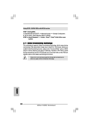
... stable overclocking environment. Using SATA / SATAII HDDs with NCQ function STEP 1: Set Up BIOS. Set the option "SATA Operation Mode" to [Manual]. Before you apply Untied Overclocking Technology. 28 ASRock H55DE3 Motherboard English Therefore, CPU FSB is untied during overclocking, FSB enjoys better margin due to fixed PCI / PCIE buses. Enter BIOS SETUP...
... stable overclocking environment. Using SATA / SATAII HDDs with NCQ function STEP 1: Set Up BIOS. Set the option "SATA Operation Mode" to [Manual]. Before you apply Untied Overclocking Technology. 28 ASRock H55DE3 Motherboard English Therefore, CPU FSB is untied during overclocking, FSB enjoys better margin due to fixed PCI / PCIE buses. Enter BIOS SETUP...
Quick Installation Guide
Page 29
... information about BIOS Setup, please refer to the User Manual (PDF file) contained in the Support CD to enter BIOS Setup utility; If you start up the computer, please press during the Power-On-Self-Test (POST) to display the menus. 29 ASRock H55DE3 Motherboard English When you wish to select among the...
... information about BIOS Setup, please refer to the User Manual (PDF file) contained in the Support CD to enter BIOS Setup utility; If you start up the computer, please press during the Power-On-Self-Test (POST) to display the menus. 29 ASRock H55DE3 Motherboard English When you wish to select among the...
