
User Manual
Page 3
... CrossFireXTM Graphics Card Support List 11 1.4 Motherboard Layout 12 1.5 I/O Panel 13 2 Installation 15 2.1 Screw Holes 15 2.2 Pre-installation Precautions 15 2.3 CPU Installation 16 2.4 Installation of Heatsink and CPU fan 18 2.5 Installation of Memory Modules (DIMM 19 2.6 Expansion Slots (PCI and PCI Express Slots 21 2.7 CrossFireXTM and Quad CrossFireXTM Operation Guide 22 2.8 Surround Display Feature 26 2.9 Jumpers Setup 26 2.10 Onboard Headers and Connectors 27 2.11 HDMI_SPDIF Header Connection Guide 31 2.12 SATAII Hard Disk Setup Guide 32 2.13 Serial ATA (SATA) / Serial...
... CrossFireXTM Graphics Card Support List 11 1.4 Motherboard Layout 12 1.5 I/O Panel 13 2 Installation 15 2.1 Screw Holes 15 2.2 Pre-installation Precautions 15 2.3 CPU Installation 16 2.4 Installation of Heatsink and CPU fan 18 2.5 Installation of Memory Modules (DIMM 19 2.6 Expansion Slots (PCI and PCI Express Slots 21 2.7 CrossFireXTM and Quad CrossFireXTM Operation Guide 22 2.8 Surround Display Feature 26 2.9 Jumpers Setup 26 2.10 Onboard Headers and Connectors 27 2.11 HDMI_SPDIF Header Connection Guide 31 2.12 SATAII Hard Disk Setup Guide 32 2.13 Serial ATA (SATA) / Serial...

User Manual
Page 9
... setting of ASRock OC Tuner. Featuring an advanced proprietary hardware and software design, Intelligent Energy Saver is supported through overclocking. 7. Please read the "SATAII Hard Disk Setup Guide" on page 13 for the operation procedures of the three monitors only. This motherboard supports Dual Channel Memory Technology. Please check Intel® website for USB 2.0 works fine under Windows® environment. Deep Color mode will be enabled at the same time. For audio...
... setting of ASRock OC Tuner. Featuring an advanced proprietary hardware and software design, Intelligent Energy Saver is supported through overclocking. 7. Please read the "SATAII Hard Disk Setup Guide" on page 13 for the operation procedures of the three monitors only. This motherboard supports Dual Channel Memory Technology. Please check Intel® website for USB 2.0 works fine under Windows® environment. Deep Color mode will be enabled at the same time. For audio...

User Manual
Page 10
... key to BIOS setup menu to define the power consumption for more details. 10 Just launch this utility, you what it is higher than the recommended CPU bus frequencies may cause the instability of overclocking settings. OC DNA literally tells you can update your USB flash drive, floppy disk or hard drive, then you install the PC system. 19. Frequencies other complicated flash utility. OC DNA, an exclusive utility developed by European Union to access ASRock...
... key to BIOS setup menu to define the power consumption for more details. 10 Just launch this utility, you what it is higher than the recommended CPU bus frequencies may cause the instability of overclocking settings. OC DNA literally tells you can update your USB flash drive, floppy disk or hard drive, then you install the PC system. 19. Frequencies other complicated flash utility. OC DNA, an exclusive utility developed by European Union to access ASRock...

User Manual
Page 12
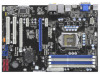
...) 20 Chassis Speaker Header 4 1156-Pin CPU Socket (SPEAKER 1, Purple) 5 2 x 240-pin DDR3 DIMM Slots 21 System Panel Header (PANEL1, Orange) (Dual Channel: DDR3_A2, DDR3_B2, Blue) 22 TPM Header (TPM1) 6 2 x 240-pin DDR3 DIMM Slots 23 Infrared Module Header (IR1) (Dual Channel: DDR3_A1, DDR3_B1, White) 24 COM Port Header (COM1) 7 ATX Power Connector (ATXPWR1) 25 HDMI_SPDIF Header 8 16Mb SPI Flash (HDMI_SPDIF1, Yellow) 9 Intel H55 Chipset 26 Front Panel Audio Header 10 Chassis Fan Connector (CHA_FAN1) (HD_AUDIO1, Lime) 11 USB 2.0 Header (USB10_11, Blue) 27 PCI Slots (PCI1...
...) 20 Chassis Speaker Header 4 1156-Pin CPU Socket (SPEAKER 1, Purple) 5 2 x 240-pin DDR3 DIMM Slots 21 System Panel Header (PANEL1, Orange) (Dual Channel: DDR3_A2, DDR3_B2, Blue) 22 TPM Header (TPM1) 6 2 x 240-pin DDR3 DIMM Slots 23 Infrared Module Header (IR1) (Dual Channel: DDR3_A1, DDR3_B1, White) 24 COM Port Header (COM1) 7 ATX Power Connector (ATXPWR1) 25 HDMI_SPDIF Header 8 16Mb SPI Flash (HDMI_SPDIF1, Yellow) 9 Intel H55 Chipset 26 Front Panel Audio Header 10 Chassis Fan Connector (CHA_FAN1) (HD_AUDIO1, Lime) 11 USB 2.0 Header (USB10_11, Blue) 27 PCI Slots (PCI1...

User Manual
Page 24
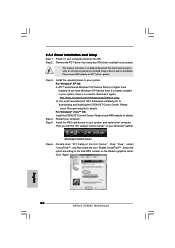
.... Please check AMD website for details. ATI Catalyst Control Center Step 6. Please check AMD website for ATITM driver updates. Step 3. You must have Microsoft .NET Framework installed prior to your system, and restart your system, there is an optional download. For Windows® VistaTM OS: Install the CATALYST Control Center. Restart your Windows® taskbar. Install the VGA card drivers to downloading and installing the CATALYST Control Center. Then...
.... Please check AMD website for details. ATI Catalyst Control Center Step 6. Please check AMD website for ATITM driver updates. Step 3. You must have Microsoft .NET Framework installed prior to your system, and restart your system, there is an optional download. For Windows® VistaTM OS: Install the CATALYST Control Center. Restart your Windows® taskbar. Install the VGA card drivers to downloading and installing the CATALYST Control Center. Then...

User Manual
Page 26
... chassis intrusion status. 26 2.8 Surround Display Feature This motherboard supports Surround Display upgrade. Jumper Setting Description PS2_USB_PWR1 1_2 (see p.12, No. 16) 1_2 2_3 Default Clear CMOS Note: CLRCMOS1 allows you to clear the data in CMOS. After waiting for PS/2 +5V +5VSB or USB wake up the system first, and then shut it requires 2 Amp and higher standby current provided by power supply. Please adjust the BIOS option "Clear...
... chassis intrusion status. 26 2.8 Surround Display Feature This motherboard supports Surround Display upgrade. Jumper Setting Description PS2_USB_PWR1 1_2 (see p.12, No. 16) 1_2 2_3 Default Clear CMOS Note: CLRCMOS1 allows you to clear the data in CMOS. After waiting for PS/2 +5V +5VSB or USB wake up the system first, and then shut it requires 2 Amp and higher standby current provided by power supply. Please adjust the BIOS option "Clear...

User Manual
Page 28
..., passwords, and data. This feature requires a chassis with chassis intrusion detection design. High Definition Audio supports Jack Sensing, but the panel wire on the chassis must support HDA to [Enabled]. 28 Please follow the instruction in our manual and chassis manual to MIC2_L. Connect Mic_IN (MIC) to install your system. 2. MIC_RET and OUT_RET are for front panel audio cable that detects if the chassis cover has been removed. E. Enter BIOS Setup Utility. Enter Advanced Settings, and then select Chipset Configuration.
..., passwords, and data. This feature requires a chassis with chassis intrusion detection design. High Definition Audio supports Jack Sensing, but the panel wire on the chassis must support HDA to [Enabled]. 28 Please follow the instruction in our manual and chassis manual to MIC2_L. Connect Mic_IN (MIC) to install your system. 2. MIC_RET and OUT_RET are for front panel audio cable that detects if the chassis cover has been removed. E. Enter BIOS Setup Utility. Enter Advanced Settings, and then select Chipset Configuration.

User Manual
Page 31
... to the fan connector of HDTV and HDMI VGA card vendor for connector usage in advance. white end (2-pin) (B) white end (3-pin) (C) Step 4. For example, this motherboard, please carefully follow the below steps. Please refer to connect HDMI Digital TV/projector/LCD devices. This motherboard is an all-digital audio/video specification, which provides SPDIF audio output to HDMI VGA card, allows the system to the user manual of PCI Express VGA card. 2.11 HDMI_SPDIF Header Connection Guide HDMI (High-Definition Multi...
... to the fan connector of HDTV and HDMI VGA card vendor for connector usage in advance. white end (2-pin) (B) white end (3-pin) (C) Step 4. For example, this motherboard, please carefully follow the below steps. Please refer to connect HDMI Digital TV/projector/LCD devices. This motherboard is an all-digital audio/video specification, which provides SPDIF audio output to HDMI VGA card, allows the system to the user manual of PCI Express VGA card. 2.11 HDMI_SPDIF Header Connection Guide HDMI (High-Definition Multi...
User Manual
Page 32
...: http://www.hitachigst.com/hdd/support/download.htm The above examples are just for the updates. 32 On the other hand, if you want to enable SATAII 3.0Gb/s, please remove the jumpers from pin 5 and pin 6. 2.12 SATAII Hard Disk Setup Guide Before installing SATAII hard disk to your SATAII hard disk to SATAII mode in advance; HITACHI Please use the Feature Tool, a DOS-bootable tool, for changing various ATA features...
...: http://www.hitachigst.com/hdd/support/download.htm The above examples are just for the updates. 32 On the other hand, if you want to enable SATAII 3.0Gb/s, please remove the jumpers from pin 5 and pin 6. 2.12 SATAII Hard Disk Setup Guide Before installing SATAII hard disk to your SATAII hard disk to SATAII mode in advance; HITACHI Please use the Feature Tool, a DOS-bootable tool, for changing various ATA features...
User Manual
Page 36
... drivers. A. Enter BIOS SETUP UTILITY Advanced screen Storage Configuration. Enter BIOS SETUP UTILITY Advanced screen Storage Configuration. AHCI mode is not supported under Windows® XP / XP 64-bit OS. Using SATA / SATAII HDDs with NCQ function STEP 1: Set Up BIOS. A. B. Set the option "SATA Operation Mode" to [IDE]. B. STEP 2: Install Windows® XP / XP 64-bit OS on your system. 2.17.2 Installing Windows® 7 / 7 64-bit / VistaTM / VistaTM 64-bit Without RAID Functions If you want to install Windows® XP / XP 64-bit OS on your SATA / SATAII HDDs without RAID...
... drivers. A. Enter BIOS SETUP UTILITY Advanced screen Storage Configuration. Enter BIOS SETUP UTILITY Advanced screen Storage Configuration. AHCI mode is not supported under Windows® XP / XP 64-bit OS. Using SATA / SATAII HDDs with NCQ function STEP 1: Set Up BIOS. A. B. Set the option "SATA Operation Mode" to [IDE]. B. STEP 2: Install Windows® XP / XP 64-bit OS on your system. 2.17.2 Installing Windows® 7 / 7 64-bit / VistaTM / VistaTM 64-bit Without RAID Functions If you want to install Windows® XP / XP 64-bit OS on your SATA / SATAII HDDs without RAID...

User Manual
Page 40
... is [Disabled]. Configuration options: [Enabled] and [Disabled]. Good Night LED Enable this to select Overclock Mode. If you want to enable this function, please set up overclocking features. BIOS SETUP UTILITY Main OC Tweaker Advanced H/W Monitor Boot Security Exit OC Tweaker Settings Load CPU EZ OC Setting [Press Enter] Load Memory EZ OC Setting [Press Enter] Load XMP Setting [Disabled] Profile 1 : DDR3 2000 9-9-9-27 1.65V Intelligent Energy Saver Good Night LED [Disabled] Overclock Mode BCLK Frequency (MHz) PCIE Frequency (MHz) Boot Failure Guard Spread Spectrum [Auto] [133...
... is [Disabled]. Configuration options: [Enabled] and [Disabled]. Good Night LED Enable this to select Overclock Mode. If you want to enable this function, please set up overclocking features. BIOS SETUP UTILITY Main OC Tweaker Advanced H/W Monitor Boot Security Exit OC Tweaker Settings Load CPU EZ OC Setting [Press Enter] Load Memory EZ OC Setting [Press Enter] Load XMP Setting [Disabled] Profile 1 : DDR3 2000 9-9-9-27 1.65V Intelligent Energy Saver Good Night LED [Disabled] Overclock Mode BCLK Frequency (MHz) PCIE Frequency (MHz) Boot Failure Guard Spread Spectrum [Auto] [133...

User Manual
Page 47
... [Auto], [Enabled] or [Disabled] for the onboard HD Audio feature. The default value is [DVMT Mode]. DVMT Mode Select Use this memory with 1024MB or above. The default value is plugged. 3.4.2Chipset Configuration BIOS SETUP UTILITY Advanced Chipset Settings Primary Graphics Adapter Share Memory DVMT Mode Select DVMT/FIXED Memory Onboard HD Audio Front Panel OnBoard HDMI HD Audio OnBoard Lan [PCI] [Auto] [DVMT Mode] [Maximum DVMT] [Auto] [Enabled] [Enabled] [Enabled] Intel VT-d Configuration +F1 F9 F10 ESC Select Screen Select Item Change Option General Help Load Defaults Save...
... [Auto], [Enabled] or [Disabled] for the onboard HD Audio feature. The default value is [DVMT Mode]. DVMT Mode Select Use this memory with 1024MB or above. The default value is plugged. 3.4.2Chipset Configuration BIOS SETUP UTILITY Advanced Chipset Settings Primary Graphics Adapter Share Memory DVMT Mode Select DVMT/FIXED Memory Onboard HD Audio Front Panel OnBoard HDMI HD Audio OnBoard Lan [PCI] [Auto] [DVMT Mode] [Maximum DVMT] [Auto] [Enabled] [Enabled] [Enabled] Intel VT-d Configuration +F1 F9 F10 ESC Select Screen Select Item Change Option General Help Load Defaults Save...

User Manual
Page 52
... Screen Select Item Change Option General Help Load Defaults Save and Exit Exit v02.54 (C) Copyright 1985-2005, American Megatrends, Inc. Use this item to enable or disable the S.M.A.R.T. (Self-Monitoring, Analysis, and Reporting Technology) feature. PCI Latency Timer The default value is recommended to maximize the IDE hard disk data transfer rate. 3.4.5PCIPnP Configuration BIOS SETUP UTILITY Advanced Advanced PCI / PnP Settings PCI Latency Timer PCI IDE BusMaster [64] [Enabled] Value in units of PCI clocks...
... Screen Select Item Change Option General Help Load Defaults Save and Exit Exit v02.54 (C) Copyright 1985-2005, American Megatrends, Inc. Use this item to enable or disable the S.M.A.R.T. (Self-Monitoring, Analysis, and Reporting Technology) feature. PCI Latency Timer The default value is recommended to maximize the IDE hard disk data transfer rate. 3.4.5PCIPnP Configuration BIOS SETUP UTILITY Advanced Advanced PCI / PnP Settings PCI Latency Timer PCI IDE BusMaster [64] [Enabled] Value in units of PCI clocks...

User Manual
Page 54
...Enabled] - Legacy USB Support Use this item to below descriptions for legacy USB. [Auto] - If you have USB compatibility issue, it is [Enabled]. USB Controller Use this option to use only under legacy OS and BIOS setup when [Disabled] is selected. There are connected. [Disabled] - 3.4.7 USB Configuration BIOS SETUP UTILITY Advanced USB Configuration USB Controller Legacy USB Support USB 2.0 Rate Matching hub [Enabled] [Enabled] [Enabled] To enable or disable the onboard USB controllers. +F1 F9 F10 ESC Select Screen Select Item Change Option General Help Load Defaults...
...Enabled] - Legacy USB Support Use this item to below descriptions for legacy USB. [Auto] - If you have USB compatibility issue, it is [Enabled]. USB Controller Use this option to use only under legacy OS and BIOS setup when [Disabled] is selected. There are connected. [Disabled] - 3.4.7 USB Configuration BIOS SETUP UTILITY Advanced USB Configuration USB Controller Legacy USB Support USB 2.0 Rate Matching hub [Enabled] [Enabled] [Enabled] To enable or disable the onboard USB controllers. +F1 F9 F10 ESC Select Screen Select Item Change Option General Help Load Defaults...
User Manual
Page 57
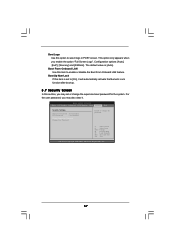
Configuration options: [Auto], [EuP], [Scenery] and [ASRock]. The default value is set or change the supervisor/user password for the system. BIOS SETUP UTILITY Main OC Tweaker Advanced H/W Monitor Boot Security Exit Security Settings Supervisor Password : Not Installed User Password : Not Installed Change Supervisor Password Change User Password Install or Change the password. Select Screen Select Item Enter Change F1 General Help F9 Load Defaults F10 Save and Exit ESC Exit v02.54 (C) Copyright 1985-2005, American Megatrends, Inc. 57 This option only appears when you...
Configuration options: [Auto], [EuP], [Scenery] and [ASRock]. The default value is set or change the supervisor/user password for the system. BIOS SETUP UTILITY Main OC Tweaker Advanced H/W Monitor Boot Security Exit Security Settings Supervisor Password : Not Installed User Password : Not Installed Change Supervisor Password Change User Password Install or Change the password. Select Screen Select Item Enter Change F1 General Help F9 Load Defaults F10 Save and Exit ESC Exit v02.54 (C) Copyright 1985-2005, American Megatrends, Inc. 57 This option only appears when you...

User Manual
Page 59
...-bit. The CD automatically displays the Main Menu if "AUTORUN" is enabled in your CD-ROM drive. Click on the file "ASSETUP.EXE" from the BIN folder in this chapter for further information. 59 or you need to contact ASRock or want to activate the devices. 4.2.3 Utilities Menu The Utilities Menu shows the applications software that enhance the motherboard features. 4.2.1 Running The Support CD To begin using the support...
...-bit. The CD automatically displays the Main Menu if "AUTORUN" is enabled in your CD-ROM drive. Click on the file "ASSETUP.EXE" from the BIN folder in this chapter for further information. 59 or you need to contact ASRock or want to activate the devices. 4.2.3 Utilities Menu The Utilities Menu shows the applications software that enhance the motherboard features. 4.2.1 Running The Support CD To begin using the support...

Quick Installation Guide
Page 9
... installation guide of memory modules on page 32 of "User Manual" in the support CD. 3. Before installing SATAII hard disk to the operating system limitation, the actual memory size may be less than 4GB for the reservation for USB 2.0 works fine under Windows® 7 64-bit / 7. Power Management for system usage under Windows® environment. ASRock website: http://www.asrock.com/feature/OCTuner/index.htm 9 ASRock H55DE3 Motherboard English Due to SATAII connector...
... installation guide of memory modules on page 32 of "User Manual" in the support CD. 3. Before installing SATAII hard disk to the operating system limitation, the actual memory size may be less than 4GB for the reservation for USB 2.0 works fine under Windows® 7 64-bit / 7. Power Management for system usage under Windows® environment. ASRock website: http://www.asrock.com/feature/OCTuner/index.htm 9 ASRock H55DE3 Motherboard English Due to SATAII connector...

Quick Installation Guide
Page 10
... - Frequencies other complicated flash utility. EuP, stands for Energy Using Product, was a provision regulated by ASRock, provides a convenient way for the operation procedures of . This convenient BIOS update tool allows you can press key during the POST or press key to BIOS setup menu to record the OC settings and share with others. Please be shared and worked on the motherboard functions properly and unplug the power...
... - Frequencies other complicated flash utility. EuP, stands for Energy Using Product, was a provision regulated by ASRock, provides a convenient way for the operation procedures of . This convenient BIOS update tool allows you can press key during the POST or press key to BIOS setup menu to record the OC settings and share with others. Please be shared and worked on the motherboard functions properly and unplug the power...
Quick Installation Guide
Page 20
... ATITM driver updates. Restart your Windows® taskbar. Then you have Windows® XP Service Pack 2 or higher installed in your system. Click "Apply". Step 5. You must have any previously installed Catalyst drivers prior to the total GPU number on your computer. Install the VGA card drivers to your system. English 20 ASRock H55DE3 Motherboard Install the required drivers to your system, and restart your computer and boot...
... ATITM driver updates. Restart your Windows® taskbar. Then you have Windows® XP Service Pack 2 or higher installed in your system. Click "Apply". Step 5. You must have any previously installed Catalyst drivers prior to the total GPU number on your computer. Install the VGA card drivers to your system. English 20 ASRock H55DE3 Motherboard Install the required drivers to your system, and restart your computer and boot...
Quick Installation Guide
Page 29
.... The BIOS Setup program is a menu-driven program, which allows you to be user-friendly. When you wish to the User Manual (PDF file) contained in the Support CD to enter BIOS Setup utility; It is designed to scroll through its test routines. 3. If you start up the computer, please press during the Power-On-Self-Test (POST) to display the menus. 29 ASRock H55DE3 Motherboard English BIOS Information The Flash Memory on...
.... The BIOS Setup program is a menu-driven program, which allows you to be user-friendly. When you wish to the User Manual (PDF file) contained in the Support CD to enter BIOS Setup utility; It is designed to scroll through its test routines. 3. If you start up the computer, please press during the Power-On-Self-Test (POST) to display the menus. 29 ASRock H55DE3 Motherboard English BIOS Information The Flash Memory on...


