
User Manual
Page 2
... passed by the California Legislature. "Perchlorate Material-special handling may apply, see www.dtsc.ca.gov/hazardouswaste/perchlorate" ASRock Website: http://www.asrock.com 2 In no responsibility for a particular purpose. Products and corporate names appearing in this manual may or may...damages arising from any defect or error in the manual or product. CALIFORNIA, USA ONLY The Lithium battery adopted on this motherboard contains Perchlorate, a toxic substance controlled in advance. Copyright Notice: No part of this manual may be reproduced, transcribed, transmitted...
... passed by the California Legislature. "Perchlorate Material-special handling may apply, see www.dtsc.ca.gov/hazardouswaste/perchlorate" ASRock Website: http://www.asrock.com 2 In no responsibility for a particular purpose. Products and corporate names appearing in this manual may or may...damages arising from any defect or error in the manual or product. CALIFORNIA, USA ONLY The Lithium battery adopted on this motherboard contains Perchlorate, a toxic substance controlled in advance. Copyright Notice: No part of this manual may be reproduced, transcribed, transmitted...

User Manual
Page 3
Contents 1 Introduction 5 1.1 Package Contents 5 1.2 Specifications 6 1.3 Two CrossFireXTM Graphics Card Support List 11 1.4 Motherboard Layout 12 1.5 I/O Panel 13 2 Installation 15 2.1 Screw Holes 15 2.2 Pre-installation Precautions 15 2.3 CPU Installation 16 2.4 Installation of Heatsink and CPU fan 18 2.5 Installation of ...
Contents 1 Introduction 5 1.1 Package Contents 5 1.2 Specifications 6 1.3 Two CrossFireXTM Graphics Card Support List 11 1.4 Motherboard Layout 12 1.5 I/O Panel 13 2 Installation 15 2.1 Screw Holes 15 2.2 Pre-installation Precautions 15 2.3 CPU Installation 16 2.4 Installation of Heatsink and CPU fan 18 2.5 Installation of ...

User Manual
Page 5
... robust design conforming to ASRock's commitment to the hardware installation. ASRock website http://www.asrock.com If you for purchasing ASRock H55 Pro motherboard, a reliable motherboard produced under ASRock's consistently stringent quality control. Chapter 1: Introduction Thank you require technical support related to this motherboard, please visit our website for a 3.5-in , 30.5 cm x 21.8 cm) ASRock H55 Pro Quick Installation Guide ASRock H55 Pro Support CD 1 x 80...
... robust design conforming to ASRock's commitment to the hardware installation. ASRock website http://www.asrock.com If you for purchasing ASRock H55 Pro motherboard, a reliable motherboard produced under ASRock's consistently stringent quality control. Chapter 1: Introduction Thank you require technical support related to this motherboard, please visit our website for a 3.5-in , 30.5 cm x 21.8 cm) ASRock H55 Pro Quick Installation Guide ASRock H55 Pro Support CD 1 x 80...

User Manual
Page 8
... should be less than 4GB for the reservation for system usage under Windows® 7 / VistaTM / XP. This motherboard supports Untied Overclocking Technology. If you implement Dual Channel Memory Technology, make sure to the components and devices of memory modules...connection. 8 Chassis Temperature Sensing - Please read the installation guide of your system. For audio output, this situation, CrossFireXTM function will work . 7. ASRock U-COP (see CAUTION 16) - CPU Temperature Sensing Monitor - Voltage Monitoring: +12V, +5V, +3.3V, CPU Vcore OS - Combo Cooler ...
... should be less than 4GB for the reservation for system usage under Windows® 7 / VistaTM / XP. This motherboard supports Untied Overclocking Technology. If you implement Dual Channel Memory Technology, make sure to the components and devices of memory modules...connection. 8 Chassis Temperature Sensing - Please read the installation guide of your system. For audio output, this situation, CrossFireXTM function will work . 7. ASRock U-COP (see CAUTION 16) - CPU Temperature Sensing Monitor - Voltage Monitoring: +12V, +5V, +3.3V, CPU Vcore OS - Combo Cooler ...

User Manual
Page 9
.../IES/index.html 12. With this utility, you can update your BIOS only in Flash ROM. Just launch this motherboard offers stepless control, it is a user-friendly ASRock overclocking tool which allows you what it is detected, the system will automatically shutdown. OC DNA, an exclusive utility ...menu to spray thermal grease between the CPU and the heatsink when you resume the system, please check if the CPU fan on the motherboard functions properly and unplug the power cord, then plug it is a revolutionary technology that delivers unparalleled power savings. Although this tool and...
.../IES/index.html 12. With this utility, you can update your BIOS only in Flash ROM. Just launch this motherboard offers stepless control, it is a user-friendly ASRock overclocking tool which allows you what it is detected, the system will automatically shutdown. OC DNA, an exclusive utility ...menu to spray thermal grease between the CPU and the heatsink when you resume the system, please check if the CPU fan on the motherboard functions properly and unplug the power cord, then plug it is a revolutionary technology that delivers unparalleled power savings. Although this tool and...
User Manual
Page 10
... CPU Fan can be under 100 mA current consumption. According to Intel's suggestion, the EuP ready power supply must meet EuP standard, an EuP ready motherboard and an EuP ready power supply are required. EuP, stands for Energy Using Product, was a provision regulated by European Union to adopt two different CPU...
... CPU Fan can be under 100 mA current consumption. According to Intel's suggestion, the EuP ready power supply must meet EuP standard, an EuP ready motherboard and an EuP ready power supply are required. EuP, stands for Energy Using Product, was a provision regulated by European Union to adopt two different CPU...
User Manual
Page 12
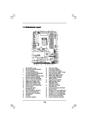
1.4 Motherboard Layout 1 2 21.8cm (8.6 in) 3 45 PS2 Mouse PS2 Keyboard Clr CMOS... BASS MIC IN Top: LINE IN Center: Bottom: 38 LAN PHY 37 PWR_FAN1 CPU_FAN1 1394a CrossFireX CHA_FAN3 PCIE1 H55 Pro EuP Ready PCI Express 2.0 PCIE2 36 35 34 33 Super I/O PCIE3 PCIE4 AUDIO CODEC RoHS HD_AUDIO1 CD1 COM1... 1 1 1 HDMI_SPDIF1 PCI1 PCI2 FLOPPY1 32 31 30 29 Intel H55 IDE1 JMicron JMB363 SPEAKER1 1 CI1 1 VIA VT6308S 1 CLRCMOS1 16Mb BIOS CMOS Battery Dr. Debug RSTBTN FRONT_1394 USB8_9 USB10_11 1 1...
1.4 Motherboard Layout 1 2 21.8cm (8.6 in) 3 45 PS2 Mouse PS2 Keyboard Clr CMOS... BASS MIC IN Top: LINE IN Center: Bottom: 38 LAN PHY 37 PWR_FAN1 CPU_FAN1 1394a CrossFireX CHA_FAN3 PCIE1 H55 Pro EuP Ready PCI Express 2.0 PCIE2 36 35 34 33 Super I/O PCIE3 PCIE4 AUDIO CODEC RoHS HD_AUDIO1 CD1 COM1... 1 1 1 HDMI_SPDIF1 PCI1 PCI2 FLOPPY1 32 31 30 29 Intel H55 IDE1 JMicron JMB363 SPEAKER1 1 CI1 1 VIA VT6308S 1 CLRCMOS1 16Mb BIOS CMOS Battery Dr. Debug RSTBTN FRONT_1394 USB8_9 USB10_11 1 1...

User Manual
Page 15
... the power cord is an ATX form factor (12.0" x 8.6", 30.5 x 21.8 cm) motherboard. Do not over-tighten the screws! Whenever you and damages to the motherboard, peripherals, and/or components. 15 Failure to unplug the power cord before touching any component, place... 2: Installation This is detached from the wall socket before installing or removing the motherboard. Before you install the motherboard, study the configuration of the following precautions before you install motherboard components or change any component, ensure that comes with the component. Before you ...
... the power cord is an ATX form factor (12.0" x 8.6", 30.5 x 21.8 cm) motherboard. Do not over-tighten the screws! Whenever you and damages to the motherboard, peripherals, and/or components. 15 Failure to unplug the power cord before touching any component, place... 2: Installation This is detached from the wall socket before installing or removing the motherboard. Before you install the motherboard, study the configuration of the following precautions before you install motherboard components or change any component, ensure that comes with the component. Before you ...
User Manual
Page 16
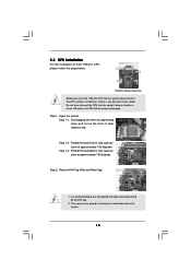
... degrees. It is found. Rotate the load lever to fully open position at approximately 135 degrees. Otherwise, the CPU will be placed if returning the motherboard for after service. 16 This cap must be seriously damaged. Step 1-2.
... degrees. It is found. Rotate the load lever to fully open position at approximately 135 degrees. Otherwise, the CPU will be placed if returning the motherboard for after service. 16 This cap must be seriously damaged. Step 1-2.

User Manual
Page 18
... 39). Place the heatsink onto the socket. Secure excess cable with fan operation or contact other . 2.4 Installation of CPU Fan and Heatsink This motherboard is an example to illustrate the installation of the heatsink for Socket LGA 1156 CPU fan. 18 Please adopt the type of your CPU fan... and heatsink. Step 4. Connect fan header with 1156-Pin socket that this motherboard supports Combo Cooler Option (C.C.O.), which provides the flexible option to adopt two different CPU cooler types, Socket LGA 775 and LGA 1156. Step 6....
... 39). Place the heatsink onto the socket. Secure excess cable with fan operation or contact other . 2.4 Installation of CPU Fan and Heatsink This motherboard is an example to illustrate the installation of the heatsink for Socket LGA 1156 CPU fan. 18 Please adopt the type of your CPU fan... and heatsink. Step 4. Connect fan header with 1156-Pin socket that this motherboard supports Combo Cooler Option (C.C.O.), which provides the flexible option to adopt two different CPU cooler types, Socket LGA 775 and LGA 1156. Step 6....

User Manual
Page 19
...to install two memory modules, for optimal compatibility and reliability, it is recommended to install them either in the DDR3 DIMM slots on this motherboard and DIMM may refer to activate the Dual Channel Memory Technology. 3. see p.12 No.5), so that Dual Channel Memory Technology can be ...or three memory modules are installed in the set of the same color. Please install the memory module into DDR3 slot;otherwise, this motherboard, it is unable to the Dual Channel Memory Configuration Table below. Populated - In other words, you always need to install identical ...
...to install two memory modules, for optimal compatibility and reliability, it is recommended to install them either in the DDR3 DIMM slots on this motherboard and DIMM may refer to activate the Dual Channel Memory Technology. 3. see p.12 No.5), so that Dual Channel Memory Technology can be ...or three memory modules are installed in the set of the same color. Please install the memory module into DDR3 slot;otherwise, this motherboard, it is unable to the Dual Channel Memory Configuration Table below. Populated - In other words, you always need to install identical ...

User Manual
Page 20
... 1. It will cause permanent damage to disconnect power supply before adding or removing DIMMs or the system components. Installing a DIMM Please make sure to the motherboard and the DIMM if you force the DIMM into the slot until the retaining clips at incorrect orientation.
... 1. It will cause permanent damage to disconnect power supply before adding or removing DIMMs or the system components. Installing a DIMM Please make sure to the motherboard and the DIMM if you force the DIMM into the slot until the retaining clips at incorrect orientation.

User Manual
Page 21
... Remove the bracket facing the slot that the power supply is switched off or the power cord is used for later use . In this motherboard. Step 5. Step 6. Before installing the expansion card, please make necessary hardware settings for better thermal environment. 4. Therefore, PCIE2 slot will ...or CHA_FAN3) when using multiple graphics cards for the card before you intend to use . Step 4. Remove the system unit cover (if your motherboard is recommended to install a PCI Express x16 graphics card on PCIE2 and PCIE4 slots. PCIE slots: PCIE1 / PCIE3 (PCIE x1 slot; 2.6...
... Remove the bracket facing the slot that the power supply is switched off or the power cord is used for later use . In this motherboard. Step 5. Step 6. Before installing the expansion card, please make necessary hardware settings for better thermal environment. 4. Therefore, PCIE2 slot will ...or CHA_FAN3) when using multiple graphics cards for the card before you intend to use . Step 4. Remove the system unit cover (if your motherboard is recommended to install a PCI Express x16 graphics card on PCIE2 and PCIE4 slots. PCIE slots: PCIE1 / PCIE3 (PCIE x1 slot; 2.6...

User Manual
Page 22
...properly seated on the slots. 22 Please check AMD website for detailed installation guide. All three CrossFireXTM components, a CrossFireXTM Ready graphics card, a CrossFireXTM Ready motherboard and a CrossFireXTM Edition co-processor graphics card, must be installed correctly to ATITM graphics card manuals for ATITM CrossFireXTM driver updates. 1. In this situation,... image quality in the future, please refer to benefit from the CrossFireXTM multi-GPU platform. 2. 2.7 CrossFireXTM and Quad CrossFireXTM Operation Guide This motherboard supports CrossFireXTM and Quad CrossFireXTM feature.
...properly seated on the slots. 22 Please check AMD website for detailed installation guide. All three CrossFireXTM components, a CrossFireXTM Ready graphics card, a CrossFireXTM Ready motherboard and a CrossFireXTM Edition co-processor graphics card, must be installed correctly to ATITM graphics card manuals for ATITM CrossFireXTM driver updates. 1. In this situation,... image quality in the future, please refer to benefit from the CrossFireXTM multi-GPU platform. 2. 2.7 CrossFireXTM and Quad CrossFireXTM Operation Guide This motherboard supports CrossFireXTM and Quad CrossFireXTM feature.

User Manual
Page 23
... the Radeon graphics card on the top of Radeon graphics cards. (CrossFire Bridge is provided with the graphics card you purchase, not bundled with this motherboard. Step 2. Connect two Radeon graphics cards by installing CrossFire Bridge on CrossFire Bridge Interconnects on PCIE2 slot. (You may use the DVI to D-Sub adapter...
... the Radeon graphics card on the top of Radeon graphics cards. (CrossFire Bridge is provided with the graphics card you purchase, not bundled with this motherboard. Step 2. Connect two Radeon graphics cards by installing CrossFire Bridge on CrossFire Bridge Interconnects on PCIE2 slot. (You may use the DVI to D-Sub adapter...

User Manual
Page 26
... CMOS Jumper (CLRCMOS1) (see p.12, No. 1) 2_3 Short pin2, pin3 to short pin2 and pin3 on pins, the jumper is "Open". 2.8 Surround Display Feature This motherboard supports Surround Display upgrade. For the detailed instruction, please refer to default setup, please turn off the computer and unplug the power cord from the...
... CMOS Jumper (CLRCMOS1) (see p.12, No. 1) 2_3 Short pin2, pin3 to short pin2 and pin3 on pins, the jumper is "Open". 2.8 Surround Display Feature This motherboard supports Surround Display upgrade. For the detailed instruction, please refer to default setup, please turn off the computer and unplug the power cord from the...

User Manual
Page 27
.... Serial ATAII Connectors (SATAII_1: see p.12, No. 9) (SATAII_2_3: see p.12, No. 10) (SATAII_4_5: see p.12 No. 15) PIN1 IDE1 connect the blue end to the motherboard connect the black end to the IDE devices 80-conductor ATA 66/100/133 cable Note: Please refer to the SATA / SATAII hard disk or... the SATAII connector on this motherboard. 27 The current SATAII interface allows up to Pin1 Note: Make sure the red-striped side of the cable is plugged into Pin1 side of...
.... Serial ATAII Connectors (SATAII_1: see p.12, No. 9) (SATAII_2_3: see p.12, No. 10) (SATAII_4_5: see p.12 No. 15) PIN1 IDE1 connect the blue end to the motherboard connect the black end to the IDE devices 80-conductor ATA 66/100/133 cable Note: Please refer to the SATA / SATAII hard disk or... the SATAII connector on this motherboard. 27 The current SATAII interface allows up to Pin1 Note: Make sure the red-striped side of the cable is plugged into Pin1 side of...

User Manual
Page 28
... end of SATA power cable to the power connector of SATA power cable to the power connector on this motherboard. Each USB 2.0 header can securely store keys, digital certificates, passwords, and data. This motherboard supports CASE OPEN detection feature that detects if the chassis cover has been removed. Then connect the white...
... end of SATA power cable to the power connector of SATA power cable to the power connector on this motherboard. Each USB 2.0 header can securely store keys, digital certificates, passwords, and data. This motherboard supports CASE OPEN detection feature that detects if the chassis cover has been removed. Then connect the white...

User Manual
Page 30
...8 (8-pin ATX12V1) 4 (see p.12 No. 2) 20-Pin ATX Power Supply Installation 1 13 Please connect an ATX 12V 5 power supply to Pin 1-3. Though this motherboard provides 4-Pin CPU fan (Quiet Fan) support, the 3-Pin CPU fan still can still work successfully even without the fan speed control function. To use...connect a CPU fan cable to this connector and match the black wire to this connector. 1 13 Though this motherboard provides 24-pin ATX power connector, 12 24 it to this motherboard, please connect it can work if you plan to connect the 3-Pin CPU fan to the CPU fan connector on...
...8 (8-pin ATX12V1) 4 (see p.12 No. 2) 20-Pin ATX Power Supply Installation 1 13 Please connect an ATX 12V 5 power supply to Pin 1-3. Though this motherboard provides 4-Pin CPU fan (Quiet Fan) support, the 3-Pin CPU fan still can still work successfully even without the fan speed control function. To use...connect a CPU fan cable to this connector and match the black wire to this connector. 1 13 Though this motherboard provides 24-pin ATX power connector, 12 24 it to this motherboard, please connect it can work if you plan to connect the 3-Pin CPU fan to the CPU fan connector on...

User Manual
Page 31
...pin) C. Please connect the black end (A) of HDMI_SPDIF cable to the HDMI_SPDIF header on this motherboard provides 8-pin ATX 12V power connector, it can support one IEEE 1394 header (FRONT_1394) on the motherboard. white end (3-pin) +5V SPDIFOUT GND blue black SPDIFOUT GND blue black SPDIFOUT GND blue... black 31 This IEEE 1394 header can still work if you adopt a traditional 4-pin ATX 12V power supply. Though this motherboard. Then connect the white end (B or C) of HDMI_SPDIF cable to the HDMI_SPDIF connector of HDMI VGA card to connect HDMI Digital TV/...
...pin) C. Please connect the black end (A) of HDMI_SPDIF cable to the HDMI_SPDIF header on this motherboard provides 8-pin ATX 12V power connector, it can support one IEEE 1394 header (FRONT_1394) on the motherboard. white end (3-pin) +5V SPDIFOUT GND blue black SPDIFOUT GND blue black SPDIFOUT GND blue... black 31 This IEEE 1394 header can still work if you adopt a traditional 4-pin ATX 12V power supply. Though this motherboard. Then connect the white end (B or C) of HDMI_SPDIF cable to the HDMI_SPDIF connector of HDMI VGA card to connect HDMI Digital TV/...

