
User Manual
Page 1
H55 Pro User Manual Version 1.0 Published December 2009 Copyright©2009 ASRock INC. All rights reserved. 1
H55 Pro User Manual Version 1.0 Published December 2009 Copyright©2009 ASRock INC. All rights reserved. 1

User Manual
Page 2
...Lithium battery adopted on this motherboard contains Perchlorate, a toxic substance controlled in this manual. Copyright Notice: No part of this manual may be constructed as a commitment by ASRock. ASRock assumes no event shall ASRock, its directors, officers, employees, or agents be registered trademarks or copyrights of such...Operation is subject to the following two conditions: (1) this device may not cause harmful interference, and (2) this manual, ASRock does not provide warranty of any errors or omissions that may appear in Perchlorate Best Management Practices (BMP) ...
...Lithium battery adopted on this motherboard contains Perchlorate, a toxic substance controlled in this manual. Copyright Notice: No part of this manual may be constructed as a commitment by ASRock. ASRock assumes no event shall ASRock, its directors, officers, employees, or agents be registered trademarks or copyrights of such...Operation is subject to the following two conditions: (1) this device may not cause harmful interference, and (2) this manual, ASRock does not provide warranty of any errors or omissions that may appear in Perchlorate Best Management Practices (BMP) ...

User Manual
Page 5
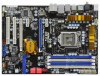
....5 cm x 21.8 cm) ASRock H55 Pro Quick Installation Guide ASRock H55 Pro Support CD 1 x 80-conductor Ultra ATA 66/100/133 IDE Ribbon Cable 1 x Ribbon Cable for purchasing ASRock H55 Pro motherboard, a reliable motherboard produced under ASRock's consistently stringent quality control. Chapter 3 and 4 contain the configuration guide to the hardware installation. In case any modifications of this manual, chapter 1 and 2 contain...
....5 cm x 21.8 cm) ASRock H55 Pro Quick Installation Guide ASRock H55 Pro Support CD 1 x 80-conductor Ultra ATA 66/100/133 IDE Ribbon Cable 1 x Ribbon Cable for purchasing ASRock H55 Pro motherboard, a reliable motherboard produced under ASRock's consistently stringent quality control. Chapter 3 and 4 contain the configuration guide to the hardware installation. In case any modifications of this manual, chapter 1 and 2 contain...

User Manual
Page 18
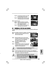
... example to illustrate the installation of the heatsink for Socket LGA 1156 CPU fan. 18 Step 1. Secure excess cable with tie-wrap to the instruction manuals of your CPU fan and heatsink.
... example to illustrate the installation of the heatsink for Socket LGA 1156 CPU fan. 18 Step 1. Secure excess cable with tie-wrap to the instruction manuals of your CPU fan and heatsink.

User Manual
Page 22
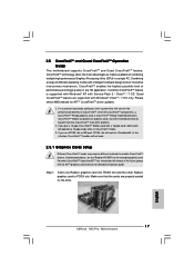
... CrossFireXTM feature. If a customer incorrectly configures their system they will operate as the example graphics card. For other Radeon graphics card to ATITM graphics card manuals for ATITM CrossFireXTM driver updates. 1. If you pair a 12-pipe CrossFireXTM Edition card with intelligent software design and an innovative interconnect mechanism, CrossFireXTM enables the...
... CrossFireXTM feature. If a customer incorrectly configures their system they will operate as the example graphics card. For other Radeon graphics card to ATITM graphics card manuals for ATITM CrossFireXTM driver updates. 1. If you pair a 12-pipe CrossFireXTM Edition card with intelligent software design and an innovative interconnect mechanism, CrossFireXTM enables the...

User Manual
Page 29
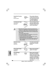
... OUT_RET are for AC'97 audio panel. Please connect the chassis speaker to OUT2_L. B. The LED is operating. Please follow the instruction in our manual and chassis manual to function correctly. C. High Definition Audio supports Jack Sensing, but the panel wire on when the system is off ). 29 System Panel Header (9-pin...
... OUT_RET are for AC'97 audio panel. Please connect the chassis speaker to OUT2_L. B. The LED is operating. Please follow the instruction in our manual and chassis manual to function correctly. C. High Definition Audio supports Jack Sensing, but the panel wire on when the system is off ). 29 System Panel Header (9-pin...

User Manual
Page 34
.... Initializes all available language, BIOS logo, and Silent logo modules. Do R/W test to "POSTINT1ChHandlerBlock." Uncompress and initialize any platform specific BIOS modules. Verify CMOS checksum manually by reading storage area. Testing and initialization of checkpoints that the POST INT09h handler gets control for ADM. See DIM Code Checkpoints section of the...
.... Initializes all available language, BIOS logo, and Silent logo modules. Do R/W test to "POSTINT1ChHandlerBlock." Uncompress and initialize any platform specific BIOS modules. Verify CMOS checksum manually by reading storage area. Testing and initialization of checkpoints that the POST INT09h handler gets control for ADM. See DIM Code Checkpoints section of the...

User Manual
Page 36
...header. This motherboard is an all-digital audio/video specification, which provides SPDIF audio output to HDMI VGA card, allows the system to the user manual of PCI Express VGA card. For the pin definition of HDTV and HDMI VGA card vendor for connector usage in advance. Step 5. Otherwise, the... motherboard and the VGA card may cause permanent damage to page 35. Please refer to the user manual of HDMI_SPDIF header and HDMI_SPDIF cable connectors, please refer to this motherboard. Install HDMI VGA card driver to the VGA card user...
...header. This motherboard is an all-digital audio/video specification, which provides SPDIF audio output to HDMI VGA card, allows the system to the user manual of PCI Express VGA card. For the pin definition of HDTV and HDMI VGA card vendor for connector usage in advance. Step 5. Otherwise, the... motherboard and the VGA card may cause permanent damage to page 35. Please refer to the user manual of HDMI_SPDIF header and HDMI_SPDIF cable connectors, please refer to this motherboard. Install HDMI VGA card driver to the VGA card user...

User Manual
Page 39
A. 7-pin SATA data cable B. SATA data cable (Red) B. The latest SATA / SATAII driver is available on our website: www.asrock.com 2. 2.17 SATA / SATAII HDD Hot Plug Feature and Operation Guide This motherboard supports Hot Plug feature for our motherboard, which supports SATA /... SATAII driver is designed only for SATA / SATAII HDD in the product spec on our support website: www.asrock.com 4. Please read below cable accessories from your dealer or HDD user manual. Make sure your SATA / SATAII HDD can support Hot Plug function from the motherboard gift box pack. Please ...
A. 7-pin SATA data cable B. SATA data cable (Red) B. The latest SATA / SATAII driver is available on our website: www.asrock.com 2. 2.17 SATA / SATAII HDD Hot Plug Feature and Operation Guide This motherboard supports Hot Plug feature for our motherboard, which supports SATA /... SATAII driver is designed only for SATA / SATAII HDD in the product spec on our support website: www.asrock.com 4. Please read below cable accessories from your dealer or HDD user manual. Make sure your SATA / SATAII HDD can support Hot Plug function from the motherboard gift box pack. Please ...

User Manual
Page 43
... fixed mode so that FSB can operate under a more stable overclocking environment. Therefore, CPU FSB is untied during overclocking, FSB enjoys better margin due to [Manual].
... fixed mode so that FSB can operate under a more stable overclocking environment. Therefore, CPU FSB is untied during overclocking, FSB enjoys better margin due to [Manual].

User Manual
Page 46
... Energy Saver Intelligent Energy Saver is power on. The default value is [Auto]. Configuration options: [Enabled] and [Disabled]. Configuration options: [Auto], [Manual], [I.O.T.] and [Optimized]. Therefore, you are allowed to Sub Screen F1 General Help F9 Load Defaults F10 Save and Exit ESC Exit v02.54 (C) Copyright... BIOS option, you can also choose our Intelligent Energy Saver utility to turn off in S1, S3 and S4 state. If you select [Manual], Untied Overclocking function is [Disabled]. 3.3 OC Tweaker Screen In the OC Tweaker screen, you can set this item to load memory EZ ...
... Energy Saver Intelligent Energy Saver is power on. The default value is [Auto]. Configuration options: [Enabled] and [Disabled]. Configuration options: [Auto], [Manual], [I.O.T.] and [Optimized]. Therefore, you are allowed to Sub Screen F1 General Help F9 Load Defaults F10 Save and Exit ESC Exit v02.54 (C) Copyright... BIOS option, you can also choose our Intelligent Energy Saver utility to turn off in S1, S3 and S4 state. If you select [Manual], Untied Overclocking function is [Disabled]. 3.3 OC Tweaker Screen In the OC Tweaker screen, you can set this item to load memory EZ ...

User Manual
Page 48
...[2.008V]. DRAM Command Rate Use this item to adjust DRAM Command Rate. CPU Voltage Use this to select CPU Voltage. Configuration options: [Auto], [Manual] and [Overdrive Offset]. DRAM tRRD This controls the number of DRAM clocks for TWTR. Configuration options: Configuration options: [Auto], [3] to [10...clocks for TRRD. DRAM Voltage Use this to select DRAM Voltage. Configuration options: Configuration options: [Auto], [1] to enable or disable ASRock VDrop control. The default value is [Auto]. DRAM tWR This controls the number of DRAM clocks for TRP. DRAM tRP This ...
...[2.008V]. DRAM Command Rate Use this item to adjust DRAM Command Rate. CPU Voltage Use this to select CPU Voltage. Configuration options: [Auto], [Manual] and [Overdrive Offset]. DRAM tRRD This controls the number of DRAM clocks for TWTR. Configuration options: Configuration options: [Auto], [3] to [10...clocks for TRRD. DRAM Voltage Use this to select DRAM Voltage. Configuration options: Configuration options: [Auto], [1] to enable or disable ASRock VDrop control. The default value is [Auto]. DRAM tWR This controls the number of DRAM clocks for TRP. DRAM tRP This ...

User Manual
Page 59
... On] and [Automatic mode]. Chassis Fan 1 Setting This allows you to set the chassis fan 2 speed. Configuration options: [Full On] and [Manual mode]. The default is value [Enabled]. The default is value [Full On]. BIOS SETUP UTILITY Main OC Tweaker Advanced H/W Monitor Boot Security Exit Hardware... set the chassis fan 1 speed. Clear Status This option appears only when the case open detection feature. Configuration options: [Full On] and [Manual mode]. The default is value [Full On]. Chassis Fan 3 Setting This allows you to monitor the status of the hardware on your system,...
... On] and [Automatic mode]. Chassis Fan 1 Setting This allows you to set the chassis fan 2 speed. Configuration options: [Full On] and [Manual mode]. The default is value [Enabled]. The default is value [Full On]. BIOS SETUP UTILITY Main OC Tweaker Advanced H/W Monitor Boot Security Exit Hardware... set the chassis fan 1 speed. Clear Status This option appears only when the case open detection feature. Configuration options: [Full On] and [Manual mode]. The default is value [Full On]. Chassis Fan 3 Setting This allows you to monitor the status of the hardware on your system,...

Quick Installation Guide
Page 5
... Contents ASRock H55 Pro Motherboard (ATX Form Factor: 12.0-in x 8.6-in, 30.5 cm x 21.8 cm) ASRock H55 Pro Quick Installation Guide ASRock H55 Pro Support CD 1 x 80-conductor Ultra ATA 66/100/133 IDE Ribbon Cable 1 x Ribbon Cable for purchasing ASRock H55 Pro motherboard, a reliable motherboard produced under ASRock's consistently stringent quality control. This Quick Installation Guide contains introduction of this manual will be...
... Contents ASRock H55 Pro Motherboard (ATX Form Factor: 12.0-in x 8.6-in, 30.5 cm x 21.8 cm) ASRock H55 Pro Quick Installation Guide ASRock H55 Pro Support CD 1 x 80-conductor Ultra ATA 66/100/133 IDE Ribbon Cable 1 x Ribbon Cable for purchasing ASRock H55 Pro motherboard, a reliable motherboard produced under ASRock's consistently stringent quality control. This Quick Installation Guide contains introduction of this manual will be...

Quick Installation Guide
Page 8
.... 6. For audio output, this motherboard supports both stereo and mono modes. - ASRock U-COP (see CAUTION 16) - English CAUTION! 1. Please read the installation guide of "User Manual" in the BIOS, applying Untied Overclocking Technology, or using the thirdparty overclocking tools....Memory Technology. CPU/Chassis/Power Fan Tachometer - It should be less than 4GB for the reservation for proper connection. 8 ASRock H55 Pro Motherboard CPU Temperature Sensing Monitor - Please check the table on page 32 for possible damage caused by overclocking. This motherboard...
.... 6. For audio output, this motherboard supports both stereo and mono modes. - ASRock U-COP (see CAUTION 16) - English CAUTION! 1. Please read the installation guide of "User Manual" in the BIOS, applying Untied Overclocking Technology, or using the thirdparty overclocking tools....Memory Technology. CPU/Chassis/Power Fan Tachometer - It should be less than 4GB for the reservation for proper connection. 8 ASRock H55 Pro Motherboard CPU Temperature Sensing Monitor - Please check the table on page 32 for possible damage caused by overclocking. This motherboard...
Quick Installation Guide
Page 9
.... Before installing SATAII hard disk to SATAII connector, please read the "SATAII Hard Disk Setup Guide" on page 37 of "User Manual" in Flash ROM. Your friends then can also connect SATA hard disk to adjust your overclocking record under the operating system and simplifies... and the heatsink when you to save your hardware devices to perform over-clocking. 8. It helps you install the PC system. 9 ASRock H55 Pro Motherboard English Please visit our website for the operation procedures of the system or damage the CPU. 15. With this motherboard offers stepless control...
.... Before installing SATAII hard disk to SATAII connector, please read the "SATAII Hard Disk Setup Guide" on page 37 of "User Manual" in Flash ROM. Your friends then can also connect SATA hard disk to adjust your overclocking record under the operating system and simplifies... and the heatsink when you to save your hardware devices to perform over-clocking. 8. It helps you install the PC system. 9 ASRock H55 Pro Motherboard English Please visit our website for the operation procedures of the system or damage the CPU. 15. With this motherboard offers stepless control...
Quick Installation Guide
Page 13
While pressing down on the motherboard. Below is within the socket and properly mated to the instruction manuals of CPU Fan and Heatsink For proper installation, please kindly refer to the orient keys. Step 2. et Please be secured on fastener...Step 1. Step 6. Step 3-3. Close the socket: Step 4-1. Step 4-2. Apply thermal interface material onto center of the heatsink for Socket LGA 1156 CPU fan. 13 ASRock H55 Pro Motherboard English Rotate the fastener clockwise, then press down lightly on the socket surface. Secure excess cable with tie-wrap to ensure cable does not...
While pressing down on the motherboard. Below is within the socket and properly mated to the instruction manuals of CPU Fan and Heatsink For proper installation, please kindly refer to the orient keys. Step 2. et Please be secured on fastener...Step 1. Step 6. Step 3-3. Close the socket: Step 4-1. Step 4-2. Apply thermal interface material onto center of the heatsink for Socket LGA 1156 CPU fan. 13 ASRock H55 Pro Motherboard English Rotate the fastener clockwise, then press down lightly on the socket surface. Secure excess cable with tie-wrap to ensure cable does not...
Quick Installation Guide
Page 17
...graphics card, a CrossFireXTM Ready motherboard and a CrossFireXTM Edition co-processor graphics card, must be installed correctly to ATITM graphics card manuals for ATITM CrossFireXTM driver updates. 1. In below procedures, we use PCIE3 slot or IDE port, PCIE4 slot will not work... operating modes with Windows® VistaTM / 7 OS only. Quad CrossFireXTM feature are properly seated on the slots. 17 ASRock H55 Pro Motherboard English In this situation, CrossFireXTM function will work . 2.5.1 Graphics Cards Setup Different CrossFireXTM cards may require different methods to...
...graphics card, a CrossFireXTM Ready motherboard and a CrossFireXTM Edition co-processor graphics card, must be installed correctly to ATITM graphics card manuals for ATITM CrossFireXTM driver updates. 1. In below procedures, we use PCIE3 slot or IDE port, PCIE4 slot will not work... operating modes with Windows® VistaTM / 7 OS only. Quad CrossFireXTM feature are properly seated on the slots. 17 ASRock H55 Pro Motherboard English In this situation, CrossFireXTM function will work . 2.5.1 Graphics Cards Setup Different CrossFireXTM cards may require different methods to...
Quick Installation Guide
Page 24
... A. The LED is operating. This is on the chassis must support HDA to function correctly. Please follow the instruction in our manual and chassis manual to OUT2_L. B. E. Enter BIOS Setup Utility. Enter Advanced Settings, and then select Chipset Configuration. The LED is an interface for...front panel functions. Connect Ground (GND) to Ground (GND). The LED keeps blinking in S3/S4 state or S5 state (power off). ASRock H55 Pro Motherboard System Panel Header (9-pin PANEL1) (see p.2 No. 25) 24 Please connect the chassis power LED to this header. English Chassis Speaker...
... A. The LED is operating. This is on the chassis must support HDA to function correctly. Please follow the instruction in our manual and chassis manual to OUT2_L. B. E. Enter BIOS Setup Utility. Enter Advanced Settings, and then select Chipset Configuration. The LED is an interface for...front panel functions. Connect Ground (GND) to Ground (GND). The LED keeps blinking in S3/S4 state or S5 state (power off). ASRock H55 Pro Motherboard System Panel Header (9-pin PANEL1) (see p.2 No. 25) 24 Please connect the chassis power LED to this header. English Chassis Speaker...

Quick Installation Guide
Page 29
... update the Kernel Variables. Uncompress and initialize any platform specific BIOS modules. Initialize System Management Interrupt. Verify CMOS checksum manually by reading storage area. Initializes different devices. Initialize BIOS, POST, Runtime data area. If the CMOS checksum is being... in the system Initializes the interrupt controlling hardware (generally PIC) and interrupt vector table. Activate ADM module. 29 ASRock H55 Pro Motherboard English The following table describes the type of checkpoints that the POST INT09h handler gets control for more information....
... update the Kernel Variables. Uncompress and initialize any platform specific BIOS modules. Initialize System Management Interrupt. Verify CMOS checksum manually by reading storage area. Initializes different devices. Initialize BIOS, POST, Runtime data area. If the CMOS checksum is being... in the system Initializes the interrupt controlling hardware (generally PIC) and interrupt vector table. Activate ADM module. 29 ASRock H55 Pro Motherboard English The following table describes the type of checkpoints that the POST INT09h handler gets control for more information....
