

User Manual
Page 4
... Contents 1 1.2 Specifications 2 1.3 Motherboard Layout 6 1.4 I/O Panel 8 Chapter 2 Installation 10 2.1 Installing the CPU 11 2.2 Installing the CPU Fan and Heatsink 14 2.3 Installing Memory Modules (DIMM) 15 2.4 Expansion Slots (PCI Express Slots) 17 2.5 Onboard Headers and Connectors 18 Chapter 3 Software and Utilities Operation 22 3.1 Installing Drivers 22 3.2 A-Tuning 23 3.3 ASRock Live Update & APP Shop 26 3.3.1 UI Overview 26 3.3.2 Apps 27 3.3.3 BIOS & Drivers 30 3.3.4 Setting 31 Chapter 4 UEFI SETUP UTILITY 32 4.1 Introduction 32 4.2 EZ Mode 33
... Contents 1 1.2 Specifications 2 1.3 Motherboard Layout 6 1.4 I/O Panel 8 Chapter 2 Installation 10 2.1 Installing the CPU 11 2.2 Installing the CPU Fan and Heatsink 14 2.3 Installing Memory Modules (DIMM) 15 2.4 Expansion Slots (PCI Express Slots) 17 2.5 Onboard Headers and Connectors 18 Chapter 3 Software and Utilities Operation 22 3.1 Installing Drivers 22 3.2 A-Tuning 23 3.3 ASRock Live Update & APP Shop 26 3.3.1 UI Overview 26 3.3.2 Apps 27 3.3.3 BIOS & Drivers 30 3.3.4 Setting 31 Chapter 4 UEFI SETUP UTILITY 32 4.1 Introduction 32 4.2 EZ Mode 33
User Manual
Page 6
... you are using. ASRock website http://www.asrock.com. 1.1 Package Contents • ASRock H310M-HDV Motherboard (Micro ATX Form Factor) • ASRock H310M-HDV Quick Installation Guide • ASRock H310M-HDV Support CD • 1 x I/O Panel Shield • 2 x Serial ATA (SATA) Data Cables (Optional) 1 English Chapter 3 contains the operation guide of the BIOS setup. It delivers excellent performance with robust design conforming to ASRock's commitment to change without further notice. Because the motherboard specifications and the BIOS software might be updated, the content...
... you are using. ASRock website http://www.asrock.com. 1.1 Package Contents • ASRock H310M-HDV Motherboard (Micro ATX Form Factor) • ASRock H310M-HDV Quick Installation Guide • ASRock H310M-HDV Support CD • 1 x I/O Panel Shield • 2 x Serial ATA (SATA) Data Cables (Optional) 1 English Chapter 3 contains the operation guide of the BIOS setup. It delivers excellent performance with robust design conforming to ASRock's commitment to change without further notice. Because the motherboard specifications and the BIOS software might be updated, the content...

User Manual
Page 8
...; ELNA Audio Caps LAN • PCIE x1 Gigabit LAN 10/100/1000 Mb/s • 1 x Realtek RTL8111H • Supports Wake-On-LAN • Supports Lightning/ESD Protection • Supports Energy Efficient Ethernet 802.3az • Supports PXE Rear Panel I/O • 1 x PS/2 Mouse/Keyboard Port • 1 x D-Sub Port • 1 x DVI-D Port • 1 x HDMI Port • 4 x USB 2.0 Ports (Supports ESD Protection) • 2 x USB 3.1 Gen1 Ports (Supports ESD Protection) • 1 x RJ-45 LAN Port with max. H310M-HDV • Three graphics output options: D-Sub...
...; ELNA Audio Caps LAN • PCIE x1 Gigabit LAN 10/100/1000 Mb/s • 1 x Realtek RTL8111H • Supports Wake-On-LAN • Supports Lightning/ESD Protection • Supports Energy Efficient Ethernet 802.3az • Supports PXE Rear Panel I/O • 1 x PS/2 Mouse/Keyboard Port • 1 x D-Sub Port • 1 x DVI-D Port • 1 x HDMI Port • 4 x USB 2.0 Ports (Supports ESD Protection) • 2 x USB 3.1 Gen1 Ports (Supports ESD Protection) • 1 x RJ-45 LAN Port with max. H310M-HDV • Three graphics output options: D-Sub...

User Manual
Page 9
... auto detect if 3-pin or 4-pin fan is in use. • 1 x 24 pin ATX Power Connector • 1 x 8 pin 12V Power Connector • 1 x Front Panel Audio Connector • 1 x USB 2.0 Header (Supports 2 USB 2.0 ports) (Supports ESD Protection) • 1 x USB 3.1 Gen1 Header (Supports 2 USB 3.1 Gen1 ports) (Supports ESD Protection) BIOS Feature • AMI UEFI Legal BIOS with multilingual GUI support • ACPI 6.0 Compliant wake up events • SMBIOS 2.7 Support • DRAM, PCH 1.05V Voltage Multi-adjustment Hardware Monitor • Temperature Sensing: CPU, Chassis/Water Pump Fans...
... auto detect if 3-pin or 4-pin fan is in use. • 1 x 24 pin ATX Power Connector • 1 x 8 pin 12V Power Connector • 1 x Front Panel Audio Connector • 1 x USB 2.0 Header (Supports 2 USB 2.0 ports) (Supports ESD Protection) • 1 x USB 3.1 Gen1 Header (Supports 2 USB 3.1 Gen1 ports) (Supports ESD Protection) BIOS Feature • AMI UEFI Legal BIOS with multilingual GUI support • ACPI 6.0 Compliant wake up events • SMBIOS 2.7 Support • DRAM, PCH 1.05V Voltage Multi-adjustment Hardware Monitor • Temperature Sensing: CPU, Chassis/Water Pump Fans...
User Manual
Page 12
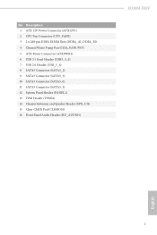
Description 1 ATX 12V Power Connector (ATX12V1) 2 CPU Fan Connector (CPU_FAN1) 3 2 x 288-pin DDR4 DIMM Slots (DDR4_A1, DDR4_B1) 4 Chassis/Water Pump Fan (CHA_FAN1/WP) 5 ATX Power Connector (ATXPWR1) 6 USB 3.1 Gen1 Header (USB3_3_4) 7 USB 2.0 Header (USB_5_6) 8 SATA3 Connector (SATA3_2) 9 SATA3 Connector (SATA3_3) 10 SATA3 Connector (SATA3_0) 11 SATA3 Connector (SATA3_1) 12 System Panel Header (PANEL1) 13 TPM Header (TPMS1) 14 Chassis Intrusion and Speaker Header (SPK_CI1) 15 Clear CMOS Pad (CLRMOS1) 16 Front Panel Audio Header (HD_AUDIO1) H310M-HDV English 7 No.
Description 1 ATX 12V Power Connector (ATX12V1) 2 CPU Fan Connector (CPU_FAN1) 3 2 x 288-pin DDR4 DIMM Slots (DDR4_A1, DDR4_B1) 4 Chassis/Water Pump Fan (CHA_FAN1/WP) 5 ATX Power Connector (ATXPWR1) 6 USB 3.1 Gen1 Header (USB3_3_4) 7 USB 2.0 Header (USB_5_6) 8 SATA3 Connector (SATA3_2) 9 SATA3 Connector (SATA3_3) 10 SATA3 Connector (SATA3_0) 11 SATA3 Connector (SATA3_1) 12 System Panel Header (PANEL1) 13 TPM Header (TPMS1) 14 Chassis Intrusion and Speaker Header (SPK_CI1) 15 Clear CMOS Pad (CLRMOS1) 16 Front Panel Audio Header (HD_AUDIO1) H310M-HDV English 7 No.

User Manual
Page 20
... may be damaged. H310M-HDV 2.3 Installing Memory Modules (DIMM) This motherboard provides two 288-pin DDR4 (Double Data Rate 4) DIMM slots, and supports Dual Channel Memory Technology. 1. It is unable to activate Dual Channel Memory Technology with only one correct orientation. For dual channel configuration, you force the DIMM into a DDR4 slot; The DIMM only fits in one memory module installed. 3. It will cause permanent damage to the motherboard and the DIMM if...
... may be damaged. H310M-HDV 2.3 Installing Memory Modules (DIMM) This motherboard provides two 288-pin DDR4 (Double Data Rate 4) DIMM slots, and supports Dual Channel Memory Technology. 1. It is unable to activate Dual Channel Memory Technology with only one correct orientation. For dual channel configuration, you force the DIMM into a DDR4 slot; The DIMM only fits in one memory module installed. 3. It will cause permanent damage to the motherboard and the DIMM if...

User Manual
Page 22
H310M-HDV 2.4 Expansion Slots (PCI Express Slots) There are 2 PCI Express slots on the motherboard. Please read the documentation of the expansion card and make sure that the power supply is switched off or the power cord is used for PCI Express x16 lane width graphics cards. 17 English PCIe slots: PCIE1 (PCIe 2.0 x1 slot) is unplugged. Before installing an expansion card, please make necessary hardware settings for PCI Express x1 lane width cards. PCIE2 (PCIe 3.0 x16 slot) is used for the card before you start the installation.
H310M-HDV 2.4 Expansion Slots (PCI Express Slots) There are 2 PCI Express slots on the motherboard. Please read the documentation of the expansion card and make sure that the power supply is switched off or the power cord is used for PCI Express x16 lane width graphics cards. 17 English PCIe slots: PCIE1 (PCIe 2.0 x1 slot) is unplugged. Before installing an expansion card, please make necessary hardware settings for PCI Express x1 lane width cards. PCIE2 (PCIe 3.0 x16 slot) is used for the card before you start the installation.

User Manual
Page 23
... jumper caps over these headers and connectors. 2.5 Onboard Headers and Connectors Onboard headers and connectors are matched correctly. PWRBTN (Power Button): Connect to the pin assignments below. RESET (Reset Button): Connect to the reset button on the chassis to the motherboard. The LED keeps blinking when the system is in S4 sleep state or powered off (S5). Note the positive and negative pins before connecting the cables. The LED is in S1/S3 sleep state. A front panel module mainly consists of power button, reset button, power LED, hard drive...
... jumper caps over these headers and connectors. 2.5 Onboard Headers and Connectors Onboard headers and connectors are matched correctly. PWRBTN (Power Button): Connect to the pin assignments below. RESET (Reset Button): Connect to the reset button on the chassis to the motherboard. The LED keeps blinking when the system is in S4 sleep state or powered off (S5). Note the positive and negative pins before connecting the cables. The LED is in S1/S3 sleep state. A front panel module mainly consists of power button, reset button, power LED, hard drive...

User Manual
Page 24
... four SATA3 connectors support SATA data cables for internal storage devices with up to this motherboard. USB_PWR GND P+ PUSB_PWR 1 There is one USB 2.0 header on this header. This USB 3.1 Gen1 header can support two ports. English 19 USB 3.1 Gen1 Header (19-pin USB3_3_4) (see p.6, No. 6) Vbus IntA_P2_SSRXIntA_P2_SSRX+ GND IntA_P2_SSTXIntA_P2_SSTX+ GND IntA_P2_DIntA_P2_D+ Vbus IntA_P3_SSRXIntA_P3_SSRX+ GND IntA_P3_SSTXIntA_P3_SSTX+ GND IntA_P3_DIntA_P3_D+ ID 1 There is one header on this motherboard. H310M-HDV Chassis Intrusion and Speaker Header (7-pin SPK_CI1...
... four SATA3 connectors support SATA data cables for internal storage devices with up to this motherboard. USB_PWR GND P+ PUSB_PWR 1 There is one USB 2.0 header on this header. This USB 3.1 Gen1 header can support two ports. English 19 USB 3.1 Gen1 Header (19-pin USB3_3_4) (see p.6, No. 6) Vbus IntA_P2_SSRXIntA_P2_SSRX+ GND IntA_P2_SSTXIntA_P2_SSTX+ GND IntA_P2_DIntA_P2_D+ Vbus IntA_P3_SSRXIntA_P3_SSRX+ GND IntA_P3_SSTXIntA_P3_SSTX+ GND IntA_P3_DIntA_P3_D+ ID 1 There is one header on this motherboard. H310M-HDV Chassis Intrusion and Speaker Header (7-pin SPK_CI1...

User Manual
Page 25
... header is for J_SENSE OUT2_R connecting audio devices MIC2_R to Pin 1-3. MIC2_L 1 1. CPU Fan Connector (4-pin CPU_FAN1) (see p.6, No. 4) GND FAN_VOLTAGE FAN_SPEED FAN_SPEED_CONTROL 1 2 34 This motherboard provides a 4-Pin water cooling chassis fan connectors. English If you plan to connect a 3-Pin CPU fan, please connect it to install your system. 2. B. C. If you plan to connect a 3-Pin chassis water cooler fan, please connect it along Pin 1 and Pin 13. High Definition Audio supports Jack Sensing, but the panel wire on the chassis must support HDA to Pin...
... header is for J_SENSE OUT2_R connecting audio devices MIC2_R to Pin 1-3. MIC2_L 1 1. CPU Fan Connector (4-pin CPU_FAN1) (see p.6, No. 4) GND FAN_VOLTAGE FAN_SPEED FAN_SPEED_CONTROL 1 2 34 This motherboard provides a 4-Pin water cooling chassis fan connectors. English If you plan to connect a 3-Pin CPU fan, please connect it to install your system. 2. B. C. If you plan to connect a 3-Pin chassis water cooler fan, please connect it along Pin 1 and Pin 13. High Definition Audio supports Jack Sensing, but the panel wire on the chassis must support HDA to Pin...

User Manual
Page 26
.... 1) TPM Header (17-pin TPMS1) (see p.6, No. 13) Clear CMOS Pad (CLRMOS1) (see p.6, No. 15) GND SERIRQ # S_PWRDWN # GN D LAD1 LAD2 SMB_DATA_MAIN SMB_CLK_MAIN GN D +3VS B LAD0 +3V LAD3 PCIRST # FRAM E PCICLK H310M-HDV 8 5 This motherboard provides an 8-pin ATX 4 1 12V power connector. To use a 4-pin ATX power supply, please plug it along Pin 1 and Pin 5. GN D This connector supports Trusted Platform Module (TPM) system, 1 which can securely store keys, digital certificates, passwords, and...
.... 1) TPM Header (17-pin TPMS1) (see p.6, No. 13) Clear CMOS Pad (CLRMOS1) (see p.6, No. 15) GND SERIRQ # S_PWRDWN # GN D LAD1 LAD2 SMB_DATA_MAIN SMB_CLK_MAIN GN D +3VS B LAD0 +3V LAD3 PCIRST # FRAM E PCICLK H310M-HDV 8 5 This motherboard provides an 8-pin ATX 4 1 12V power connector. To use a 4-pin ATX power supply, please plug it along Pin 1 and Pin 5. GN D This connector supports Trusted Platform Module (TPM) system, 1 which can securely store keys, digital certificates, passwords, and...
User Manual
Page 27
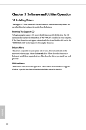
... English Utilities Menu The Utilities Menu shows the application software that enhance the motherboard's features. Therefore, the drivers you install can work properly. Click on the support CD driver page. Running The Support CD To begin using the support CD, insert the CD into your computer. If the Main Menu does not appear automatically, locate and double click on the file "ASRSETUP.EXE" in your CD-ROM drive. Please click Install...
... English Utilities Menu The Utilities Menu shows the application software that enhance the motherboard's features. Therefore, the drivers you install can work properly. Click on the support CD driver page. Running The Support CD To begin using the support CD, insert the CD into your computer. If the Main Menu does not appear automatically, locate and double click on the file "ASRSETUP.EXE" in your CD-ROM drive. Please click Install...

User Manual
Page 53
.... CPU Thermal Throttling Enable CPU internal thermal control mechanisms to enable or disable Software Controlled Software Guard Extensions (SGX). 48 English CFG Lock This item allows you to run multiple operating systems and applications in independent partitions, so that one computer system can function as multiple virtual systems. Hardware Prefetcher Automatically prefetch data and code for the processor. Intel Virtualization Technology Intel Virtualization Technology allows a platform to disable...
.... CPU Thermal Throttling Enable CPU internal thermal control mechanisms to enable or disable Software Controlled Software Guard Extensions (SGX). 48 English CFG Lock This item allows you to run multiple operating systems and applications in independent partitions, so that one computer system can function as multiple virtual systems. Hardware Prefetcher Automatically prefetch data and code for the processor. Intel Virtualization Technology Intel Virtualization Technology allows a platform to disable...
User Manual
Page 54
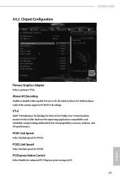
... Link Speed Select the link speed for PCIE2. 4.6.2 Chipset Configuration H310M-HDV Primary Graphics Adapter Select a primary VGA. PCI Express Native Control Select Enable for Directed I/O helps your virtual machine monitor better utilize hardware by improving application compatibility and reliability, and providing additional levels of manageability, security, isolation, and I/O performance. VT-d Intel® Virtualization Technology for enhanced PCI Express power saving in Above 4G Address Space (only if the system supports 64 bit PCI...
... Link Speed Select the link speed for PCIE2. 4.6.2 Chipset Configuration H310M-HDV Primary Graphics Adapter Select a primary VGA. PCI Express Native Control Select Enable for Directed I/O helps your virtual machine monitor better utilize hardware by improving application compatibility and reliability, and providing additional levels of manageability, security, isolation, and I/O performance. VT-d Intel® Virtualization Technology for enhanced PCI Express power saving in Above 4G Address Space (only if the system supports 64 bit PCI...

User Manual
Page 55
... Memory Configure the size of memory that is installed. DMI ASPM Support This option enables/disables the control of the DMI Link. Deep Sleep Configure deep sleep mode for all PCH DMI devices. Onboard HD Audio Enable/disable onboard HD audio. IGPU Multi-Monitor Select disable to disable the integrated graphics when an external graphics card is allocated to boot up . Restore on CPU side of ASPM on AC/Power Loss Select the power state after a power failure. PCIE ASPM Support This option enables/disables the ASPM support for power...
... Memory Configure the size of memory that is installed. DMI ASPM Support This option enables/disables the control of the DMI Link. Deep Sleep Configure deep sleep mode for all PCH DMI devices. Onboard HD Audio Enable/disable onboard HD audio. IGPU Multi-Monitor Select disable to disable the integrated graphics when an external graphics card is allocated to boot up . Restore on CPU side of ASPM on AC/Power Loss Select the power state after a power failure. PCIE ASPM Support This option enables/disables the ASPM support for power...

User Manual
Page 59
XHCI Hand-off support. 4.6.6 USB Configuration Legacy USB Support Enable or disable Legacy OS Support for OSes without XHCI hand-off This is recommended to support USB devices under the UEFI setup and Windows/Linux operating systems only. The XHCI ownership change should be claimed by XHCI driver. 54 English Select UEFI Setup Only to disable legacy USB support. If you encounter USB compatibility issues it is a workaround for USB 2.0 devices.
XHCI Hand-off support. 4.6.6 USB Configuration Legacy USB Support Enable or disable Legacy OS Support for OSes without XHCI hand-off This is recommended to support USB devices under the UEFI setup and Windows/Linux operating systems only. The XHCI ownership change should be claimed by XHCI driver. 54 English Select UEFI Setup Only to disable legacy USB support. If you encounter USB compatibility issues it is a workaround for USB 2.0 devices.
User Manual
Page 61
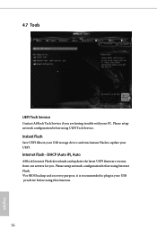
4.7 Tools UEFI Tech Service Contact ASRock Tech Service if you . Please setup network configuration before using Internet Flash. *For BIOS backup and recovery purpose, it is recommended to plug in your USB storage device and run Instant Flash to update your PC. Internet Flash - DHCP (Auto IP), Auto ASRock Internet Flash downloads and updates the latest UEFI firmware version from our servers for you are having trouble with your UEFI. Instant Flash Save UEFI files in your USB pen drive before using UEFI Tech Service. Please setup network configuration before using this...
4.7 Tools UEFI Tech Service Contact ASRock Tech Service if you . Please setup network configuration before using Internet Flash. *For BIOS backup and recovery purpose, it is recommended to plug in your USB storage device and run Instant Flash to update your PC. Internet Flash - DHCP (Auto IP), Auto ASRock Internet Flash downloads and updates the latest UEFI firmware version from our servers for you are having trouble with your UEFI. Instant Flash Save UEFI files in your USB pen drive before using UEFI Tech Service. Please setup network configuration before using this...

User Manual
Page 62
H310M-HDV Internet Setting Enable or disable sound effects in the setup utility. UEFI Download Server Select a server to configure internet connection settings for Internet Flash. Network Configuration Use this to download the UEFI firmware. 57 English
H310M-HDV Internet Setting Enable or disable sound effects in the setup utility. UEFI Download Server Select a server to configure internet connection settings for Internet Flash. Network Configuration Use this to download the UEFI firmware. 57 English
User Manual
Page 64
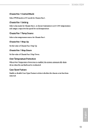
... Enable or disable Case Open Feature to set 5 CPU temperatures and assign a respective fan speed for Chassis Fan 1, or choose Customize to detect whether the chassis cover has been removed. 59 English Chassis Fan 1 Setting Select a fan mode for each temperature. Chassis Fan 1 Step Down Set the value of Chassis Fan 1 Step Up. Over Temperature Protection When Over Temperature Protection is enabled, the system automatically shuts down when the motherboard is overheated. Chassis Fan 1 Temp Source Select a fan temperature source for Chassis Fan 1. H310M-HDV Chassis Fan 1 Control...
... Enable or disable Case Open Feature to set 5 CPU temperatures and assign a respective fan speed for Chassis Fan 1, or choose Customize to detect whether the chassis cover has been removed. 59 English Chassis Fan 1 Setting Select a fan mode for each temperature. Chassis Fan 1 Step Down Set the value of Chassis Fan 1 Step Up. Over Temperature Protection When Over Temperature Protection is enabled, the system automatically shuts down when the motherboard is overheated. Chassis Fan 1 Temp Source Select a fan temperature source for Chassis Fan 1. H310M-HDV Chassis Fan 1 Control...

User Manual
Page 65
... settings in the UEFI Setup Utility. Leave it blank and press enter to remove the password. Secure Boot Use this option to enable or disable support for the user account. Disable this item to use discrete TPM Module. 60 English Supervisor Password Set or change the password for Secure Boot. User Password Set or change the password for the system. Users are unable to change the supervisor/user password for the administrator account. Intel(R) Platform Trust Technology Enable/disable Intel PTT in the UEFI Setup Utility...
... settings in the UEFI Setup Utility. Leave it blank and press enter to remove the password. Secure Boot Use this option to enable or disable support for the user account. Disable this item to use discrete TPM Module. 60 English Supervisor Password Set or change the password for Secure Boot. User Password Set or change the password for the system. Users are unable to change the supervisor/user password for the administrator account. Intel(R) Platform Trust Technology Enable/disable Intel PTT in the UEFI Setup Utility...


