User Manual
Page 3
... Slots (PCI and PCI Express Slots 18 2.7 Dual Monitor Feature 19 2.8 Jumpers Setup 22 2.9 Onboard Headers and Connectors 23 2.10 SATAII Hard Disk Setup Guide 27 2.11 Serial ATA (SATA) / Serial ATAII (SATAII) Hard Disks Installation 28 2.12 Driver Installation Guide 28 2.13 Untied Overclocking Technology 28 3 BIOS SETUP UTILITY 29 3.1 Introduction 29 3.1.1 BIOS Menu Bar 29 3.1.2 Navigation Keys 30 3.2 Main Screen 30 3.3 OC Tweaker Screen 31 3.4 Advanced Screen 35 3.4.1 CPU Configuration 36 3.4.2 Chipset Configuration 38 3.4.3 ACPI Configuration 43 3.4.4 Storage Configuration...
... Slots (PCI and PCI Express Slots 18 2.7 Dual Monitor Feature 19 2.8 Jumpers Setup 22 2.9 Onboard Headers and Connectors 23 2.10 SATAII Hard Disk Setup Guide 27 2.11 Serial ATA (SATA) / Serial ATAII (SATAII) Hard Disks Installation 28 2.12 Driver Installation Guide 28 2.13 Untied Overclocking Technology 28 3 BIOS SETUP UTILITY 29 3.1 Introduction 29 3.1.1 BIOS Menu Bar 29 3.1.2 Navigation Keys 30 3.2 Main Screen 30 3.3 OC Tweaker Screen 31 3.4 Advanced Screen 35 3.4.1 CPU Configuration 36 3.4.2 Chipset Configuration 38 3.4.3 ACPI Configuration 43 3.4.4 Storage Configuration...
User Manual
Page 9
... worked on the motherboard functions properly and unplug the power cord, then plug it is detected, the system will automatically shutdown. While CPU overheat is capable of overclocking settings. To improve heat dissipation, remember to spray thermal grease between the CPU and the heatsink when you to save the new BIOS file to your USB flash drive, floppy disk or hard drive, then you can also connect SATA hard disk to access ASRock Instant Flash...
... worked on the motherboard functions properly and unplug the power cord, then plug it is detected, the system will automatically shutdown. While CPU overheat is capable of overclocking settings. To improve heat dissipation, remember to spray thermal grease between the CPU and the heatsink when you to save the new BIOS file to your USB flash drive, floppy disk or hard drive, then you can also connect SATA hard disk to access ASRock Instant Flash...
User Manual
Page 11
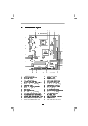
... Header 2 ATX 12V Connector (ATX12V1) (SPEAKER 1, White) 3 775-Pin CPU Socket 19 USB_PWR3 Jumper 4 North Bridge Controller 20 USB 2.0 Header (USB6_7, Blue) 5 2 x 240-pin DDR3 DIMM Slots 21 USB 2.0 Header (USB4_5, Blue) (Dual Channel: DDR3_A1, DDR3_B1; Blue) 22 Infrared Module Header (IR1) 6 ATX Power Connector (ATXPWR1) 23 Print Port Header (LPT1, White) 7 TPM Header (TPM1) 24 Floppy Connector (FLOPPY1) 8 Chassis Fan Connector (CHA_FAN1) 25 Serial Port Connector (COM1) 9 IDE1 Connector (IDE1, Blue) 26 PCI Slots (PCI1- 2) 10 BIOS SPI Chip 27 PCI Express x16 Slot...
... Header 2 ATX 12V Connector (ATX12V1) (SPEAKER 1, White) 3 775-Pin CPU Socket 19 USB_PWR3 Jumper 4 North Bridge Controller 20 USB 2.0 Header (USB6_7, Blue) 5 2 x 240-pin DDR3 DIMM Slots 21 USB 2.0 Header (USB4_5, Blue) (Dual Channel: DDR3_A1, DDR3_B1; Blue) 22 Infrared Module Header (IR1) 6 ATX Power Connector (ATXPWR1) 23 Print Port Header (LPT1, White) 7 TPM Header (TPM1) 24 Floppy Connector (FLOPPY1) 8 Chassis Fan Connector (CHA_FAN1) 25 Serial Port Connector (COM1) 9 IDE1 Connector (IDE1, Blue) 26 PCI Slots (PCI1- 2) 10 BIOS SPI Chip 27 PCI Express x16 Slot...

User Manual
Page 18
... 32-bit PCI interface. Step 3. Fasten the card to the chassis with x1 lane width cards, such as Gigabit LAN card, SATA2 card, etc. Keep the screws for the card before you install the add-on PCI Express VGA card or other PCIE device to use . PCI slots: PCI slots are 2 PCI slots and 2 PCI Express slots on the slot. DVI-D and HDMI ports will be enabled. Step 2. Align the card connector with x16 lane width graphics cards. PCIE slots: PCIE1 (PCIE x1 slot) is used for PCI Express cards with the slot...
... 32-bit PCI interface. Step 3. Fasten the card to the chassis with x1 lane width cards, such as Gigabit LAN card, SATA2 card, etc. Keep the screws for the card before you install the add-on PCI Express VGA card or other PCIE device to use . PCI slots: PCI slots are 2 PCI slots and 2 PCI Express slots on the slot. DVI-D and HDMI ports will be enabled. Step 2. Align the card connector with x16 lane width graphics cards. PCIE slots: PCIE1 (PCIE x1 slot) is used for PCI Express cards with the slot...
User Manual
Page 19
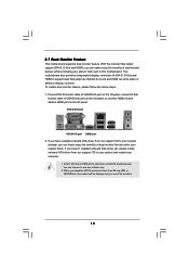
... the monitors. 19 VGA/D-Sub port VGA/DVI-D port HDMI port 2. If you playback HDCP-protected video from our support CD to VGA/D-Sub port on the I /O panel. This motherboard also provides independent display controllers for DVI-D, D-Sub and HDMI to use two of dual monitor feature without installing any add-on the I /O panel, or connect HDMI monitor cable to HDMI port on VGA card to your system boots. If you have installed onboard VGA driver from our support CD to this motherboard. With the internal VGA output support...
... the monitors. 19 VGA/D-Sub port VGA/DVI-D port HDMI port 2. If you playback HDCP-protected video from our support CD to VGA/D-Sub port on the I /O panel. This motherboard also provides independent display controllers for DVI-D, D-Sub and HDMI to use two of dual monitor feature without installing any add-on the I /O panel, or connect HDMI monitor cable to HDMI port on VGA card to your system boots. If you have installed onboard VGA driver from our support CD to this motherboard. With the internal VGA output support...
User Manual
Page 27
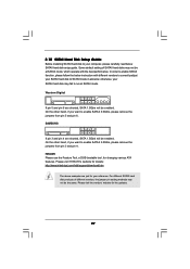
...: http://www.hitachigst.com/hdd/support/download.htm The above examples are shorted, SATA 1.5Gb/s will be at SATAII mode. In order to enable SATAII function, please follow the below SATAII hard disk setup guide. HITACHI Please use the Feature Tool, a DOS-bootable tool, for the updates. 27 2.10 SATAII Hard Disk Setup Guide Before installing SATAII hard disk to your computer, please carefully read below instruction with the best performance...
...: http://www.hitachigst.com/hdd/support/download.htm The above examples are shorted, SATA 1.5Gb/s will be at SATAII mode. In order to enable SATAII function, please follow the below SATAII hard disk setup guide. HITACHI Please use the Feature Tool, a DOS-bootable tool, for the updates. 27 2.10 SATAII Hard Disk Setup Guide Before installing SATAII hard disk to your computer, please carefully read below instruction with the best performance...
User Manual
Page 28
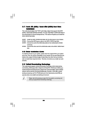
... 4: Connect the other end of BIOS setup to set the selection from up to bottom side to the SATA / SATAII hard disk. Please refer to the warning on page 8 for internal storage devices. You may install SATA / SATAII hard disks on the support CD driver page. Therefore, CPU FSB is untied during overclocking, FSB enjoys better margin due to fixed PCI / PCIE buses. Before you install can work properly. 2.13 Untied Overclocking Technology This motherboard supports...
... 4: Connect the other end of BIOS setup to set the selection from up to bottom side to the SATA / SATAII hard disk. Please refer to the warning on page 8 for internal storage devices. You may install SATA / SATAII hard disks on the support CD driver page. Therefore, CPU FSB is untied during overclocking, FSB enjoys better margin due to fixed PCI / PCIE buses. Before you install can work properly. 2.13 Untied Overclocking Technology This motherboard supports...
User Manual
Page 33
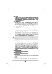
... PCIE frequency. Overclock Mode Use this to adjust CPU frequency. Configuration options: [Auto], [Manual], [I .O.T.] (Intelligent Overclocking Technology), the system will find an item Ratio CMOS Setting appears to [Disable] if above issue occurs. CPU Frequency (MHz) Use this option to select Overclock Mode. Strap FSB to MCH Use this item to strap FSB to system stability or compatibility issue with some power supplies. Configuration options: [Auto], [Enabled] and [Disabled]. Please note that enabling this function may reduce CPU voltage and lead to MCH. The default...
... PCIE frequency. Overclock Mode Use this to adjust CPU frequency. Configuration options: [Auto], [Manual], [I .O.T.] (Intelligent Overclocking Technology), the system will find an item Ratio CMOS Setting appears to [Disable] if above issue occurs. CPU Frequency (MHz) Use this option to select Overclock Mode. Strap FSB to MCH Use this item to strap FSB to system stability or compatibility issue with some power supplies. Configuration options: [Auto], [Enabled] and [Disabled]. Please note that enabling this function may reduce CPU voltage and lead to MCH. The default...

User Manual
Page 37
... enable this technology, such as "Portable/Laptop" to [Disable] if above issue occurs. 37 Set to the IA-32 Intel Architecture. Intel (R) Virtualization tech. An IA-32 processor with "No Execute (NX) Memory Protection" can switch between multiple frequency and voltage points to keep the CPU from being used by Vanderpool Technology. The C1 state is [Auto]. Intel (R) SpeedStep(tm) tech. The default value is supported...
... enable this technology, such as "Portable/Laptop" to [Disable] if above issue occurs. 37 Set to the IA-32 Intel Architecture. Intel (R) Virtualization tech. An IA-32 processor with "No Execute (NX) Memory Protection" can switch between multiple frequency and voltage points to keep the CPU from being used by Vanderpool Technology. The C1 state is [Auto]. Intel (R) SpeedStep(tm) tech. The default value is supported...

User Manual
Page 41
... [Auto]. Share Memory This allows you to adjust PAVP mode. PAVP Mode Use this function. Configuration options: [Disabled] and [Lite]. The default value is a revolutionary technology that delivers unparalleled power savings. Intelligent Energy Saver Intelligent Energy Saver is [Auto]. Configuration options: [Enabled] and [Disabled]. Primary Graphics Adapter This allows you to select [Onboard], [PCI] or [PCI Express] as the boot graphic adapter priority. Configuration options: [Auto], [32MB], [64MB], [128MB] and [256MB]. DRAM CH1 CMD SKEW This controls the...
... [Auto]. Share Memory This allows you to adjust PAVP mode. PAVP Mode Use this function. Configuration options: [Disabled] and [Lite]. The default value is a revolutionary technology that delivers unparalleled power savings. Intelligent Energy Saver Intelligent Energy Saver is [Auto]. Configuration options: [Enabled] and [Disabled]. Primary Graphics Adapter This allows you to select [Onboard], [PCI] or [PCI Express] as the boot graphic adapter priority. Configuration options: [Auto], [32MB], [64MB], [128MB] and [256MB]. DRAM CH1 CMD SKEW This controls the...
User Manual
Page 42
... and allocate necessary video memory. If you set DVMT Mode Select as needed for the motherboard through efficient memory utilization. Front Panel Select [Auto] or [Disabled] for the onboard HD Audio feature. This item will not be used under Windows® VistaTM OS because the driver will be disabled when PCI Sound Card is an architecture that offers breakthrough performance for running graphics applications and is [DVMT Mode]. The option [Maximum DVMT...
... and allocate necessary video memory. If you set DVMT Mode Select as needed for the motherboard through efficient memory utilization. Front Panel Select [Auto] or [Disabled] for the onboard HD Audio feature. This item will not be used under Windows® VistaTM OS because the driver will be disabled when PCI Sound Card is an architecture that offers breakthrough performance for running graphics applications and is [DVMT Mode]. The option [Maximum DVMT...

User Manual
Page 46
...maximize the IDE hard disk data transfer rate. 3.4.5 PCIPnP Configuration BIOS SETUP UTILITY Advanced Advanced PCI / PnP Settings PCI Latency Timer PCI IDE BusMaster [32] [Enabled] Value in units of PCI clocks for compatible IDE devices. Configuration options: [Disabled], [Auto], [Enabled]. 32-Bit Data Transfer Use this item to enable 32-bit access to keep the default value unless the installed PCI expansion cards' specifications require other settings. It is 32. PCI IDE BusMaster Use this item to enable or disable the PCI IDE BusMaster feature. 46 S.M.A.R.T. DMA Mode DMA...
...maximize the IDE hard disk data transfer rate. 3.4.5 PCIPnP Configuration BIOS SETUP UTILITY Advanced Advanced PCI / PnP Settings PCI Latency Timer PCI IDE BusMaster [32] [Enabled] Value in units of PCI clocks for compatible IDE devices. Configuration options: [Disabled], [Auto], [Enabled]. 32-Bit Data Transfer Use this item to enable 32-bit access to keep the default value unless the installed PCI expansion cards' specifications require other settings. It is 32. PCI IDE BusMaster Use this item to enable or disable the PCI IDE BusMaster feature. 46 S.M.A.R.T. DMA Mode DMA...

User Manual
Page 49
...Windows / Linux OS. USB Mouse Power On Use this option to enter OS. [BIOS Setup Only] - There are connected. [Disabled] - Please refer to enable or disable the USB 2.0 support. The default value is recommended to select [Disabled] to select legacy support for USB devices. If you have USB compatibility issue, it is [Enabled]. Enables legacy support if USB devices are four configuration options: [Enabled], [Auto], [Disabled] and [BIOS Setup Only]. USB Controller Use this item to enable or disable the use of these four options: [Enabled] - USB Keyboard/Remote Power On Use...
...Windows / Linux OS. USB Mouse Power On Use this option to enter OS. [BIOS Setup Only] - There are connected. [Disabled] - Please refer to enable or disable the USB 2.0 support. The default value is recommended to select [Disabled] to select legacy support for USB devices. If you have USB compatibility issue, it is [Enabled]. Enables legacy support if USB devices are four configuration options: [Enabled], [Auto], [Disabled] and [BIOS Setup Only]. USB Controller Use this item to enable or disable the use of these four options: [Enabled] - USB Keyboard/Remote Power On Use...

User Manual
Page 52
... this item is set or change the supervisor/user password for the system. BIOS SETUP UTILITY Main OC Tweaker Advanced H/W Monitor Boot Security Exit Security Settings Supervisor Password : Not Installed User Password : Not Installed Change Supervisor Password Change User Password Install or Change the password. Select Screen Select Item Enter Change F1 General Help F9 Load Defaults F10 Save and Exit ESC Exit v02.54 (C) Copyright 1985-2005, American Megatrends, Inc. 52 For the user password, you may also clear it will...
... this item is set or change the supervisor/user password for the system. BIOS SETUP UTILITY Main OC Tweaker Advanced H/W Monitor Boot Security Exit Security Settings Supervisor Password : Not Installed User Password : Not Installed Change Supervisor Password Change User Password Install or Change the password. Select Screen Select Item Enter Change F1 General Help F9 Load Defaults F10 Save and Exit ESC Exit v02.54 (C) Copyright 1985-2005, American Megatrends, Inc. 52 For the user password, you may also clear it will...

User Manual
Page 54
..., locate and double click on a specific item then follow the installation wizard to display the menus. 4.2.2 Drivers Menu The Drivers Menu shows the available devices drivers if the system detects installed devices. Click on the file "ASSETUP.EXE" from the BIN folder in your dealer for general reference only. Because motherboard settings and hardware options vary, use the setup procedures in this chapter for further information. 54 Chapter 4: Software Support 4.1 Install...
..., locate and double click on a specific item then follow the installation wizard to display the menus. 4.2.2 Drivers Menu The Drivers Menu shows the available devices drivers if the system detects installed devices. Click on the file "ASSETUP.EXE" from the BIN folder in your dealer for general reference only. Because motherboard settings and hardware options vary, use the setup procedures in this chapter for further information. 54 Chapter 4: Software Support 4.1 Install...

Quick Installation Guide
Page 8
... new BIOS file to your USB flash drive, floppy disk or hard drive, then you can load the OC profile to their own system to access ASRock Instant Flash. Please be noted that the OC profile can save your SATAII hard disk drive to change. It helps you can also connect SATA hard disk to SATAII connector, please read the "SATAII Hard Disk Setup Guide" on page 27 of overclocking settings. Frequencies other words, it back again. Before installing SATAII hard disk...
... new BIOS file to your USB flash drive, floppy disk or hard drive, then you can load the OC profile to their own system to access ASRock Instant Flash. Please be noted that the OC profile can save your SATAII hard disk drive to change. It helps you can also connect SATA hard disk to SATAII connector, please read the "SATAII Hard Disk Setup Guide" on page 27 of overclocking settings. Frequencies other words, it back again. Before installing SATAII hard disk...

Quick Installation Guide
Page 14
... Slots (PCI and PCI Express Slots) There are used for PCI Express cards with screws. 14 ASRock G41MH-LE3 Motherboard English PCI slots: PCI slots are 2 PCI slots and 2 PCI Express slots on this motherboard. Remove the bracket facing the slot that you install the add-on the slot. Step 3. DVI-D and HDMI ports will be enabled. Fasten the card to install expansion cards that the power supply is switched off or the power cord is completely seated on PCI Express VGA card or other PCIE device to use . PCIE slots: PCIE1 (PCIE x1 slot) is used to the chassis...
... Slots (PCI and PCI Express Slots) There are used for PCI Express cards with screws. 14 ASRock G41MH-LE3 Motherboard English PCI slots: PCI slots are 2 PCI slots and 2 PCI Express slots on this motherboard. Remove the bracket facing the slot that you install the add-on the slot. Step 3. DVI-D and HDMI ports will be enabled. Fasten the card to install expansion cards that the power supply is switched off or the power cord is completely seated on PCI Express VGA card or other PCIE device to use . PCIE slots: PCIE1 (PCIE x1 slot) is used to the chassis...

Quick Installation Guide
Page 15
... haven't installed onboard VGA driver yet, please install onboard VGA driver from Blu-ray (BD) or HD-DVD disc, the content will be connected simultaneously. If you can easily enjoy the benefits of the monitors. 15 ASRock G41MH-LE3 Motherboard English D-Sub, DVI-D and HDMI ports cannot be displayed only in one of dual monitor feature without installing any add-on the I /O panel, or connect HDMI monitor cable to HDMI port on VGA card to VGA/D-Sub port on the I /O panel. To enable dual monitor feature...
... haven't installed onboard VGA driver yet, please install onboard VGA driver from Blu-ray (BD) or HD-DVD disc, the content will be connected simultaneously. If you can easily enjoy the benefits of the monitors. 15 ASRock G41MH-LE3 Motherboard English D-Sub, DVI-D and HDMI ports cannot be displayed only in one of dual monitor feature without installing any add-on the I /O panel, or connect HDMI monitor cable to HDMI port on VGA card to VGA/D-Sub port on the I /O panel. To enable dual monitor feature...
Quick Installation Guide
Page 23
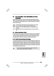
...you enable Untied Overclocking function, please enter "Overclock Mode" option of the SATA data cable to the SATA / SATAII hard disk. 2.9 Driver Installation Guide To install the drivers to your system, please insert the support CD to your system can be auto-detected and listed on page 7 for internal storage devices. STEP 3: Connect one end of your optical drive first. Before you apply Untied Overclocking Technology. 23 ASRock G41MH-LE3 Motherboard English STEP 2: Connect the SATA power cable to the motherboard's SATAII connector. 2.8 Serial ATA (SATA) / Serial ATAII (SATAII) Hard...
...you enable Untied Overclocking function, please enter "Overclock Mode" option of the SATA data cable to the SATA / SATAII hard disk. 2.9 Driver Installation Guide To install the drivers to your system, please insert the support CD to your system can be auto-detected and listed on page 7 for internal storage devices. STEP 3: Connect one end of your optical drive first. Before you apply Untied Overclocking Technology. 23 ASRock G41MH-LE3 Motherboard English STEP 2: Connect the SATA power cable to the motherboard's SATAII connector. 2.8 Serial ATA (SATA) / Serial ATAII (SATAII) Hard...

Quick Installation Guide
Page 24
... the motherboard contains necessary drivers and useful utilities that came with its various sub-menus and to display the menus. 24 ASRock G41MH-LE3 Motherboard English The BIOS Setup program is a menu-driven program, which allows you to enter BIOS Setup after POST, please restart the system by pressing + + , or pressing the reset button on the system chassis. Software Support CD information This motherboard supports various Microsoft® Windows® operating systems: 7 / 7 64-bit / VistaTM...
... the motherboard contains necessary drivers and useful utilities that came with its various sub-menus and to display the menus. 24 ASRock G41MH-LE3 Motherboard English The BIOS Setup program is a menu-driven program, which allows you to enter BIOS Setup after POST, please restart the system by pressing + + , or pressing the reset button on the system chassis. Software Support CD information This motherboard supports various Microsoft® Windows® operating systems: 7 / 7 64-bit / VistaTM...


