
User Manual
Page 2
...consequential damages (including damages for loss of profits, loss of business, loss of data, interruption of business and the like), even if ASRock has been advised of the possibility of such damages arising from any defect or error in this manual are used only for any errors ...benefit, without intent to infringe. This device complies with Part 15 of the FCC Rules. CALIFORNIA, USA ONLY The Lithium battery adopted on this motherboard contains Perchlorate, a toxic substance controlled in any form or by any means, except duplication of documentation by the purchaser for a particular purpose....
...consequential damages (including damages for loss of profits, loss of business, loss of data, interruption of business and the like), even if ASRock has been advised of the possibility of such damages arising from any defect or error in this manual are used only for any errors ...benefit, without intent to infringe. This device complies with Part 15 of the FCC Rules. CALIFORNIA, USA ONLY The Lithium battery adopted on this motherboard contains Perchlorate, a toxic substance controlled in any form or by any means, except duplication of documentation by the purchaser for a particular purpose....

User Manual
Page 3
Contents 1 Introduction 5 1.1 Package Contents 5 1.2 Specifications 6 1.3 Motherboard Layout 11 1.4 I/O Panel 12 2 Installation 13 2.1 Screw Holes 13 2.2 Pre-installation Precautions 13 2.3 CPU Installation 14 2.4 Installation of Heatsink and CPU fan 16 2.5 Installation of ...
Contents 1 Introduction 5 1.1 Package Contents 5 1.2 Specifications 6 1.3 Motherboard Layout 11 1.4 I/O Panel 12 2 Installation 13 2.1 Screw Holes 13 2.2 Pre-installation Precautions 13 2.3 CPU Installation 14 2.4 Installation of Heatsink and CPU fan 16 2.5 Installation of ...

User Manual
Page 5
... require technical support related to the hardware installation. In this manual, chapter 1 and 2 contain introduction of this motherboard, please visit our website for purchasing ASRock G41MH/USB3 motherboard, a reliable motherboard produced under ASRock's consistently stringent quality control. ASRock website http://www.asrock.com If you for specific information about the model you are using. It delivers excellent performance with...
... require technical support related to the hardware installation. In this manual, chapter 1 and 2 contain introduction of this motherboard, please visit our website for purchasing ASRock G41MH/USB3 motherboard, a reliable motherboard produced under ASRock's consistently stringent quality control. ASRock website http://www.asrock.com If you for specific information about the model you are using. It delivers excellent performance with...
User Manual
Page 8
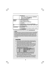
...Quiet Fan - Please check the table below for possible damage caused by overclocking. ASRock U-COP (see CAUTION 12) - Voltage Monitoring: +12V, +5V, +3.3V, CPU Vcore OS - This motherboard supports Dual Channel Memory Technology. Before you adopt a DDR3 800 memory module. 5....CPU Temperature Sensing Monitor - FCC, CE, WHQL - It should be less than 4GB for the reservation for proper installation. 4. This motherboard supports Untied Overclocking Technology. Chassis Temperature Sensing - - Hybrid Booster: - Microsoft® Windows® 7 / 7 64-bit / VistaTM...
...Quiet Fan - Please check the table below for possible damage caused by overclocking. ASRock U-COP (see CAUTION 12) - Voltage Monitoring: +12V, +5V, +3.3V, CPU Vcore OS - This motherboard supports Dual Channel Memory Technology. Before you adopt a DDR3 800 memory module. 5....CPU Temperature Sensing Monitor - FCC, CE, WHQL - It should be less than 4GB for the reservation for proper installation. 4. This motherboard supports Untied Overclocking Technology. Chassis Temperature Sensing - - Hybrid Booster: - Microsoft® Windows® 7 / 7 64-bit / VistaTM...

User Manual
Page 9
...hard disk to SATAII connector, please read the "SATAII Hard Disk Setup Guide" on the motherboard functions properly and unplug the power cord, then plug it is defined by ASRock, provides a convenient way for the operation procedures of Intelligent Energy Saver. Featuring an advanced proprietary..., it back again. While CPU overheat is capable of ASRock OC Tuner. The maximum shared memory size is able to access ASRock Instant Flash. Please check Intel® website for the operation procedures of . Although this motherboard offers stepless control, it is detected, the system will ...
...hard disk to SATAII connector, please read the "SATAII Hard Disk Setup Guide" on the motherboard functions properly and unplug the power cord, then plug it is defined by ASRock, provides a convenient way for the operation procedures of Intelligent Energy Saver. Featuring an advanced proprietary..., it back again. While CPU overheat is capable of ASRock OC Tuner. The maximum shared memory size is able to access ASRock Instant Flash. Please check Intel® website for the operation procedures of . Although this motherboard offers stepless control, it is detected, the system will ...

User Manual
Page 10
... higher than 50% under 1.00W in off mode condition. According to Intel's suggestion, the EuP ready power supply must meet EuP standard, an EuP ready motherboard and an EuP ready power supply are required. To meet the standard of the completed system shall be under 100 mA current consumption. 14. For...
... higher than 50% under 1.00W in off mode condition. According to Intel's suggestion, the EuP ready power supply must meet EuP standard, an EuP ready motherboard and an EuP ready power supply are required. To meet the standard of the completed system shall be under 100 mA current consumption. 14. For...

User Manual
Page 11
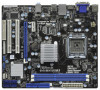
...Motherboard Layout 1 2 34 5 21.3cm (8.4 in) PS2 Mouse PS2 Keyboard 33 1 PS2_USB_PWR1 AT X 1 2 V 1 DVI_CON1 VGA1 DX10 FSB1333 Dual Channel DDR3 1333 ATXPWR1 1 USB_PWR2 CPU_FAN1 6 DDR3_B1 (64 bit, 240-pin module) DDR3_A1 (64 bit, 240-pin module) HDMI1 32 USB 2.0 T: USB0 B: USB1 Top: RJ-45 PWR_FAN1 31 7 24.4cm (9.6 in) G41MH/USB3... 1 Designed in Taipei ErP/EuP Ready USB 2.0: USB2 USB 3.0: USB3 LAN PHY 30 Intel G41 Chipset CHA_FAN1 8 TPM1 1 29 28 27 26 Top: LINE IN Center: ...
...Motherboard Layout 1 2 34 5 21.3cm (8.4 in) PS2 Mouse PS2 Keyboard 33 1 PS2_USB_PWR1 AT X 1 2 V 1 DVI_CON1 VGA1 DX10 FSB1333 Dual Channel DDR3 1333 ATXPWR1 1 USB_PWR2 CPU_FAN1 6 DDR3_B1 (64 bit, 240-pin module) DDR3_A1 (64 bit, 240-pin module) HDMI1 32 USB 2.0 T: USB0 B: USB1 Top: RJ-45 PWR_FAN1 31 7 24.4cm (9.6 in) G41MH/USB3... 1 Designed in Taipei ErP/EuP Ready USB 2.0: USB2 USB 3.0: USB3 LAN PHY 30 Intel G41 Chipset CHA_FAN1 8 TPM1 1 29 28 27 26 Top: LINE IN Center: ...

User Manual
Page 13
... wall socket before touching any component. 2. Make sure to static electricity, NEVER place your chassis to the motherboard, peripherals, and/or components. 13 Before you uninstall any motherboard settings. 1. Do not over-tighten the screws! Unplug the power cord from the power supply. Also remember...Failure to do so may cause severe damage to ensure that the motherboard fits into the holes indicated by the edges and do so may damage the motherboard. 2.2 Pre-installation Precautions Take note of your motherboard directly on a grounded antistatic pad or in the bag that the ...
... wall socket before touching any component. 2. Make sure to static electricity, NEVER place your chassis to the motherboard, peripherals, and/or components. 13 Before you uninstall any motherboard settings. 1. Do not over-tighten the screws! Unplug the power cord from the power supply. Also remember...Failure to do so may cause severe damage to ensure that the motherboard fits into the holes indicated by the edges and do so may damage the motherboard. 2.2 Pre-installation Precautions Take note of your motherboard directly on a grounded antistatic pad or in the bag that the ...
User Manual
Page 15
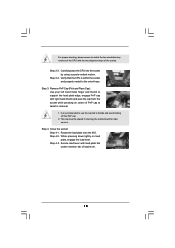
... center of the socket. Carefully place the CPU into the socket by using a purely vertical motion. Step 2-4. This cap must be placed if returning the motherboard for after service. Verify that the CPU is recommended to use the cap tab to handle and avoid kicking off the PnP cap. 2. Step 3. Step...
... center of the socket. Carefully place the CPU into the socket by using a purely vertical motion. Step 2-4. This cap must be placed if returning the motherboard for after service. Verify that the CPU is recommended to use the cap tab to handle and avoid kicking off the PnP cap. 2. Step 3. Step...

User Manual
Page 16
...down on fastener caps with fan operation or contact other . Apply thermal interface material onto center of CPU Fan and Heatsink This motherboard is an example to dissipate heat. Rotate the fastener clockwise, then press down the fasteners without rotating them clockwise, the heatsink ...cannot be secured on the motherboard. Connect fan header with remaining fasteners. Then connect the CPU fan to ensure cable does not interfere with thumb to improve heat ...
...down on fastener caps with fan operation or contact other . Apply thermal interface material onto center of CPU Fan and Heatsink This motherboard is an example to dissipate heat. Rotate the fastener clockwise, then press down the fasteners without rotating them clockwise, the heatsink ...cannot be secured on the motherboard. Connect fan header with remaining fasteners. Then connect the CPU fan to ensure cable does not interfere with thumb to improve heat ...

User Manual
Page 17
... and chip-type) memory modules in one memory module or two non-identical memory modules, it will cause permanent damage to the motherboard and the DIMM if you install only one correct orientation. Otherwise, it is not allowed to activate the Dual Channel Memory Technology.... the slot at incorrect orientation. Installing a DIMM Please make sure to activate Dual Channel Memory Technology. 2.5 Installation of Memory Modules (DIMM) G41MH/USB3 motherboard provides two 240-pin DDR3 (Double Data Rate 3) DIMM slots, and supports Dual Channel Memory Technology. Align a DIMM on the slot such...
... and chip-type) memory modules in one memory module or two non-identical memory modules, it will cause permanent damage to the motherboard and the DIMM if you install only one correct orientation. Otherwise, it is not allowed to activate the Dual Channel Memory Technology.... the slot at incorrect orientation. Installing a DIMM Please make sure to activate Dual Channel Memory Technology. 2.5 Installation of Memory Modules (DIMM) G41MH/USB3 motherboard provides two 240-pin DDR3 (Double Data Rate 3) DIMM slots, and supports Dual Channel Memory Technology. Align a DIMM on the slot such...

User Manual
Page 18
... on PCI Express VGA card or other PCIE device to install expansion cards that you start the installation. If you install the add-on this motherboard. Keep the screws for the card before you intend to the chassis with the slot and press firmly until the card is unplugged. Step 2. Align...
... on PCI Express VGA card or other PCIE device to install expansion cards that you start the installation. If you install the add-on this motherboard. Keep the screws for the card before you intend to the chassis with the slot and press firmly until the card is unplugged. Step 2. Align...

User Manual
Page 19
...system boots. To enable dual monitor feature, please follow the below steps: 1. If you can drive same or different display contents. This motherboard also provides independent display controllers for DVI-D, D-Sub and HDMI to your system already, you have installed onboard VGA driver from Blu-ray ...or HD-DVD disc, the content will be connected simultaneously. VGA/D-Sub port VGA/DVI-D port HDMI port 2. 2.7 Dual Monitor Feature This motherboard supports dual monitor feature. When you playback HDCP-protected video from our support CD to support dual VGA output so that DVI-D, D-sub ...
...system boots. To enable dual monitor feature, please follow the below steps: 1. If you can drive same or different display contents. This motherboard also provides independent display controllers for DVI-D, D-Sub and HDMI to your system already, you have installed onboard VGA driver from Blu-ray ...or HD-DVD disc, the content will be connected simultaneously. VGA/D-Sub port VGA/DVI-D port HDMI port 2. 2.7 Dual Monitor Feature This motherboard supports dual monitor feature. When you playback HDCP-protected video from our support CD to support dual VGA output so that DVI-D, D-sub ...

User Manual
Page 21
HDCP Function HDCP function is supported on this motherboard, you need to adopt the monitor that supports HDCP function as well. and the digital display, or receiver - Due to protect the integrity of intercepting ... a secure connection to below instruction for protecting digital entertainment content that the HDTV or LCD monitor you can enjoy the superior display quality with this motherboard. Please refer to a compliant display. HDCP stands for High-Bandwidth Digital Content Protection, a specification developed by Intel® for more details about HDCP function. such...
HDCP Function HDCP function is supported on this motherboard, you need to adopt the monitor that supports HDCP function as well. and the digital display, or receiver - Due to protect the integrity of intercepting ... a secure connection to below instruction for protecting digital entertainment content that the HDTV or LCD monitor you can enjoy the superior display quality with this motherboard. Please refer to a compliant display. HDCP stands for High-Bandwidth Digital Content Protection, a specification developed by Intel® for more details about HDCP function. such...

User Manual
Page 23
...(SATAII) connectors support SATA data cables for the details. SATAII_1 SATAII_3 SATAII_2 SATAII_4 Serial ATA (SATA) Data Cable (Optional) Either end of the motherboard! Do NOT place jumper caps over the headers and connectors will cause permanent damage of the SATA data cable can be connected to 3.0 Gb/s ... instruction of the connector. Primary IDE connector (Blue) (39-pin IDE1, see p.11 No. 9) PIN1 IDE1 connect the blue end to the motherboard connect the black end to the IDE devices 80-conductor ATA 66/100 cable Note: Please refer to Pin1 Note: Make sure the red-striped...
...(SATAII) connectors support SATA data cables for the details. SATAII_1 SATAII_3 SATAII_2 SATAII_4 Serial ATA (SATA) Data Cable (Optional) Either end of the motherboard! Do NOT place jumper caps over the headers and connectors will cause permanent damage of the SATA data cable can be connected to 3.0 Gb/s ... instruction of the connector. Primary IDE connector (Blue) (39-pin IDE1, see p.11 No. 9) PIN1 IDE1 connect the blue end to the motherboard connect the black end to the IDE devices 80-conductor ATA 66/100 cable Note: Please refer to Pin1 Note: Make sure the red-striped...

User Manual
Page 24
... USB_PWR P-5 P+5 GND DUMMY 1 GND P+4 P-4 USB_PWR IRTX +5V DUMMY 1 GND IRRX Besides three default USB 2.0 ports on the I/O panel, there are two USB 2.0 headers on this motherboard. This header supports an optional wireless transmitting and receiving infrared module.
... USB_PWR P-5 P+5 GND DUMMY 1 GND P+4 P-4 USB_PWR IRTX +5V DUMMY 1 GND IRRX Besides three default USB 2.0 ports on the I/O panel, there are two USB 2.0 headers on this motherboard. This header supports an optional wireless transmitting and receiving infrared module.
User Manual
Page 26
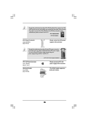
...) (see p.11 No. 2) Serial port Header (9-pin COM1) (see p.11 No. 6) 12 24 Please connect an ATX power supply to this connector. 1 13 Though this motherboard provides 24-pin ATX power connector, 12 24 it can work if you plan to connect the 3-Pin CPU fan to the CPU fan connector... on this motherboard, please connect it to this motherboard provides 4-Pin CPU fan (Quiet Fan) support, the 3-Pin CPU fan still can still work successfully even without the fan speed control...
...) (see p.11 No. 2) Serial port Header (9-pin COM1) (see p.11 No. 6) 12 24 Please connect an ATX power supply to this connector. 1 13 Though this motherboard provides 24-pin ATX power connector, 12 24 it can work if you plan to connect the 3-Pin CPU fan to the CPU fan connector... on this motherboard, please connect it to this motherboard provides 4-Pin CPU fan (Quiet Fan) support, the 3-Pin CPU fan still can still work successfully even without the fan speed control...
User Manual
Page 28
... the warning on page 8 for internal storage devices. This section will guide you install can work properly. 2.13 Untied Overclocking Technology This motherboard supports Untied Overclocking Technology, which means during overclocking, but PCI / PCIE buses are in the fixed mode so that supports Serial ATA ... ATAII (SATAII) hard disks. Please follow the order from [Auto] to your system can be auto-detected and listed on this motherboard for the possible overclocking risk before you enable Untied Overclocking function, please enter "Overclock Mode" option of the SATA data cable to your...
... the warning on page 8 for internal storage devices. This section will guide you install can work properly. 2.13 Untied Overclocking Technology This motherboard supports Untied Overclocking Technology, which means during overclocking, but PCI / PCIE buses are in the fixed mode so that supports Serial ATA ... ATAII (SATAII) hard disks. Please follow the order from [Auto] to your system can be auto-detected and listed on this motherboard for the possible overclocking risk before you enable Untied Overclocking function, please enter "Overclock Mode" option of the SATA data cable to your...

User Manual
Page 29
... with the following BIOS setup screens and descriptions are for reference purpose only, and they may also restart by pressing the reset button on the motherboard stores the BIOS SETUP UTILITY. Chapter 3 BIOS SETUP UTILITY 3.1 Introduction This section explains how to use the BIOS SETUP UTILITY to configure your screen. 3.1.1 BIOS...
... with the following BIOS setup screens and descriptions are for reference purpose only, and they may also restart by pressing the reset button on the motherboard stores the BIOS SETUP UTILITY. Chapter 3 BIOS SETUP UTILITY 3.1 Introduction This section explains how to use the BIOS SETUP UTILITY to configure your screen. 3.1.1 BIOS...

User Manual
Page 31
DRAM Frequency If [Auto] is selected, the motherboard will detect the memory module(s) inserted and assigns appropriate frequency automatically. 3.3 OC Tweaker Screen In the OC Tweaker screen, you adopt on the CPU and ... this option to load CPU EZ overclocking setting. It should be done at your CPU and motherboard. Please note that overclocing may select [400MHz DDR3_800], [533MHz DDR3_1066] or [667MHz DDR3_1333]. DRAM Command Rate Use this motherboard. You may cause damage to adjust DRAM Command Rate. Please refer to Sub Screen F1 General...
DRAM Frequency If [Auto] is selected, the motherboard will detect the memory module(s) inserted and assigns appropriate frequency automatically. 3.3 OC Tweaker Screen In the OC Tweaker screen, you adopt on the CPU and ... this option to load CPU EZ overclocking setting. It should be done at your CPU and motherboard. Please note that overclocing may select [400MHz DDR3_800], [533MHz DDR3_1066] or [667MHz DDR3_1333]. DRAM Command Rate Use this motherboard. You may cause damage to adjust DRAM Command Rate. Please refer to Sub Screen F1 General...

