
User Manual
Page 3
Contents 1 Introduction 5 1.1 Package Contents 5 1.2 Specifications 6 1.3 Motherboard Layout (G41M-VGS3 / G41M-VS3) ......... 10 1.4 I/O Panel (G41M-VGS3 11 1.5 I/O Panel (G41M-VS3 12 2 Installation 13 2.1 Screw Holes 13 2.2 Pre-installation Precautions 13 2.3 CPU Installation 14 2.4 ... / Serial ATAII (SATAII) Hard Disks Installation 24 2.11 Driver Installation Guide 24 2.12 Untied Overclocking Technology 24 3 BIOS SETUP UTILITY 25 3.1 Introduction 25 3.1.1 BIOS Menu Bar 25 3.1.2 Navigation Keys 26 3.2 Main Screen 26 3.3 OC Tweaker Screen 28 3.4 Advanced Screen 31 3.4.1 CPU...
Contents 1 Introduction 5 1.1 Package Contents 5 1.2 Specifications 6 1.3 Motherboard Layout (G41M-VGS3 / G41M-VS3) ......... 10 1.4 I/O Panel (G41M-VGS3 11 1.5 I/O Panel (G41M-VS3 12 2 Installation 13 2.1 Screw Holes 13 2.2 Pre-installation Precautions 13 2.3 CPU Installation 14 2.4 ... / Serial ATAII (SATAII) Hard Disks Installation 24 2.11 Driver Installation Guide 24 2.12 Untied Overclocking Technology 24 3 BIOS SETUP UTILITY 25 3.1 Introduction 25 3.1.1 BIOS Menu Bar 25 3.1.2 Navigation Keys 26 3.2 Main Screen 26 3.3 OC Tweaker Screen 28 3.4 Advanced Screen 31 3.4.1 CPU...
User Manual
Page 5
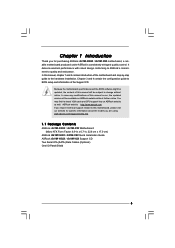
... lists on ASRock website without notice. www.asrock.com/support/index.asp 1.1 Package Contents ASRock G41M-VGS3 / G41M-VS3 Motherboard (Micro ATX Form Factor: 8.9-in x 6.7-in, 22.6 cm x 17.0 cm) ASRock G41M-VGS3 / G41M-VS3 Quick Installation Guide ASRock G41M-VGS3 / G41M-VS3 Support CD Two Serial ATA (SATA) Data Cables (Optional) One I/O Panel Shield 5 Chapter 3 and 4 contain the configuration guide to BIOS setup and...
... lists on ASRock website without notice. www.asrock.com/support/index.asp 1.1 Package Contents ASRock G41M-VGS3 / G41M-VS3 Motherboard (Micro ATX Form Factor: 8.9-in x 6.7-in, 22.6 cm x 17.0 cm) ASRock G41M-VGS3 / G41M-VS3 Quick Installation Guide ASRock G41M-VGS3 / G41M-VS3 Support CD Two Serial ATA (SATA) Data Cables (Optional) One I/O Panel Shield 5 Chapter 3 and 4 contain the configuration guide to BIOS setup and...
User Manual
Page 7
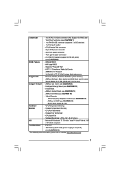
... DVD Suite and Creative Sound Blaster X-Fi MB) (OEM and Trial Version) Unique Feature - ASRock U-COP (see CAUTION 11) - FCC, CE - AMI Legal BIOS - VCCM, NB, VTT, GTLRef Voltage Multi-adjustment Support CD - Chassis Temperature Sensing - CPU...-bit / XP / XP 64-bit compliant Certifications - ASRock OC DNA (see CAUTION 9) - CPU Temperature Sensing Monitor - Connector - 4 x SATAII 3.0 Gb/s connectors (No Support for RAID and "Hot Plug" functions) (see CAUTION 8) BIOS Feature - 8Mb AMI BIOS - Boot Failure Guard (B.F.G.) Hardware - Front panel audio ...
... DVD Suite and Creative Sound Blaster X-Fi MB) (OEM and Trial Version) Unique Feature - ASRock U-COP (see CAUTION 11) - FCC, CE - AMI Legal BIOS - VCCM, NB, VTT, GTLRef Voltage Multi-adjustment Support CD - Chassis Temperature Sensing - CPU...-bit / XP / XP 64-bit compliant Certifications - ASRock OC DNA (see CAUTION 9) - CPU Temperature Sensing Monitor - Connector - 4 x SATAII 3.0 Gb/s connectors (No Support for RAID and "Hot Plug" functions) (see CAUTION 8) BIOS Feature - 8Mb AMI BIOS - Boot Failure Guard (B.F.G.) Hardware - Front panel audio ...
User Manual
Page 8
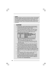
... memory size is defined by the chipset vendor and is a certain risk involved with 64-bit CPU, there is a user-friendly ASRock overclocking tool which allows you to surveil your system stability, or even cause damage to the components and devices of "Hyper Threading Technology... Untied Overclocking Technology. Please refer to read the "SATAII Hard Disk Setup Guide" on this motherboard, it will operate in the BIOS, applying Untied Overclocking Technology, or using the thirdparty overclocking tools. Before you need to adjust the jumper. Please check the table below...
... memory size is defined by the chipset vendor and is a certain risk involved with 64-bit CPU, there is a user-friendly ASRock overclocking tool which allows you to surveil your system stability, or even cause damage to the components and devices of "Hyper Threading Technology... Untied Overclocking Technology. Please refer to read the "SATAII Hard Disk Setup Guide" on this motherboard, it will operate in the BIOS, applying Untied Overclocking Technology, or using the thirdparty overclocking tools. Before you need to adjust the jumper. Please check the table below...

User Manual
Page 9
... share with others. EuP, stands for Energy Using Product, was a provision regulated by ASRock, provides a convenient way for the completed system. Just launch this tool and save the new BIOS file to EuP, the total AC power of Intelligent Energy Saver. OC DNA, an... under 100 mA current consumption. According to update system BIOS without sacrificing computing performance. Please visit our website for more details. 9 ASRock website: http://www.asrock.com 11. With this motherboard offers stepless control, it is a BIOS flash utility embedded in off mode condition. OC DNA ...
... share with others. EuP, stands for Energy Using Product, was a provision regulated by ASRock, provides a convenient way for the completed system. Just launch this tool and save the new BIOS file to EuP, the total AC power of Intelligent Energy Saver. OC DNA, an... under 100 mA current consumption. According to update system BIOS without sacrificing computing performance. Please visit our website for more details. 9 ASRock website: http://www.asrock.com 11. With this motherboard offers stepless control, it is a BIOS flash utility embedded in off mode condition. OC DNA ...

User Manual
Page 10
...BIOS SPI Chip 6 North Bridge Controller 20 PCI Slot (PCI1) 7 South Bridge Controller 21 EUP Audio Jumper (EUP_AUDIO1) 8 System Panel Header (PANEL1, Orange) 22 EUP LAN Jumper (EUP_LAN1) 9 IDE1 Connector (IDE1, Blue) 23 PCI Express x16 Slot (PCIE1) 10 Primary SATAII Connector (SATAII_1; 1.3 Motherboard Layout (G41M-VGS3 / G41M-VS3... In 24 HD_AUDIO1 LAN PHY LPT1 FSB1 1 23 1 6 22 EUP_LAN 1 PCIE1 21 1 EUP_AUDIO1 20 AUDIO 19 CODEC 8Mb BIOS CMOS Battery RoHS DX10 Intel ICH7 7 18 PCI1 USB6_7 17 CHA_FAN1 1 SPEAKER1 CLRCMOS1 1 PLED PWRBTN 1 PANEL 1 IDE1 8 ...
...BIOS SPI Chip 6 North Bridge Controller 20 PCI Slot (PCI1) 7 South Bridge Controller 21 EUP Audio Jumper (EUP_AUDIO1) 8 System Panel Header (PANEL1, Orange) 22 EUP LAN Jumper (EUP_LAN1) 9 IDE1 Connector (IDE1, Blue) 23 PCI Express x16 Slot (PCIE1) 10 Primary SATAII Connector (SATAII_1; 1.3 Motherboard Layout (G41M-VGS3 / G41M-VS3... In 24 HD_AUDIO1 LAN PHY LPT1 FSB1 1 23 1 6 22 EUP_LAN 1 PCIE1 21 1 EUP_AUDIO1 20 AUDIO 19 CODEC 8Mb BIOS CMOS Battery RoHS DX10 Intel ICH7 7 18 PCI1 USB6_7 17 CHA_FAN1 1 SPEAKER1 CLRCMOS1 1 PLED PWRBTN 1 PANEL 1 IDE1 8 ...

User Manual
Page 18
... and PCI Express Slots) There are 1 PCI slot and 1 PCI Express slot on PCI Express VGA card to PCIE1 (PCIE x16 slot) and adjust the BIOS options "Primary Graphics Adapter" to [Onboard] and "Share Memory" to [Auto], then the onboard VGA will be enabled, and the primary screen will be onboard...
... and PCI Express Slots) There are 1 PCI slot and 1 PCI Express slot on PCI Express VGA card to PCIE1 (PCIE x16 slot) and adjust the BIOS options "Primary Graphics Adapter" to [Onboard] and "Share Memory" to [Auto], then the onboard VGA will be enabled, and the primary screen will be onboard...

User Manual
Page 21
... install your system. 2. You don't need to OUT2_L. Connect Audio_R (RIN) to OUT2_R and Audio_L (LIN) to connect them for HD audio panel only. Enter BIOS Setup Utility. USB 2.0 Headers (9-pin USB6_7) (see p.10 No. 17) (9-pin USB4_5) (see p.10 No. 15) USB_PWR P-7 P+7 GND DUMMY 1 GND P+6 P-6 USB_PWR USB_PWR P-5 P+5 GND DUMMY 1 GND...
... install your system. 2. You don't need to OUT2_L. Connect Audio_R (RIN) to OUT2_R and Audio_L (LIN) to connect them for HD audio panel only. Enter BIOS Setup Utility. USB 2.0 Headers (9-pin USB6_7) (see p.10 No. 17) (9-pin USB4_5) (see p.10 No. 15) USB_PWR P-7 P+7 GND DUMMY 1 GND P+6 P-6 USB_PWR USB_PWR P-5 P+5 GND DUMMY 1 GND...

User Manual
Page 24
..., but PCI / PCIE buses are in the fixed mode so that supports Serial ATA (SATA) / Serial ATAII (SATAII) hard disks. STEP 3: Connect one end of BIOS setup to set the selection from up to bottom side to the motherboard's SATAII connector. Please follow the order from [Auto] to the warning on...
..., but PCI / PCIE buses are in the fixed mode so that supports Serial ATA (SATA) / Serial ATAII (SATAII) hard disks. STEP 3: Connect one end of BIOS setup to set the selection from up to bottom side to the motherboard's SATAII connector. Please follow the order from [Auto] to the warning on...

User Manual
Page 25
...bar, and then press to get into the sub screen. 25 Please press or during the Power-On-Self-Test (POST) to enter the BIOS SETUP UTILITY, otherwise, POST will continue with the following selections: Main To set up the system time/date information OC Tweaker To set up ...overclocking features Advanced To set up the advanced BIOS features H/W Monitor To display current hardware status Boot To set up the default system device to locate and load the Operating System Security To...
...bar, and then press to get into the sub screen. 25 Please press or during the Power-On-Self-Test (POST) to enter the BIOS SETUP UTILITY, otherwise, POST will continue with the following selections: Main To set up the system time/date information OC Tweaker To set up ...overclocking features Advanced To set up the advanced BIOS features H/W Monitor To display current hardware status Boot To set up the default system device to locate and load the Operating System Security To...

User Manual
Page 26
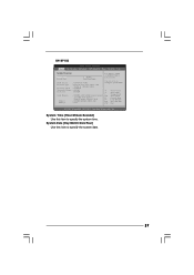
...jump to the Exit Screen or exit the current screen 3.2 Main Screen When you enter the BIOS SETUP UTILITY, the Main screen will appear and display the system overview G41M-VGS3 BIOS SETUP UTILITY Main OC Tweaker Advanced H/W Monitor Boot Security Exit System Overview System Time System Date ...[14:00:09] [Fri 12/18/2009] BIOS Version : G41M-VGS3 P1.00 Processor Type : Intel (R) Core (TM) 2 Duo CPU E6850 @ 3.00GHz (64bit) Processor Speed : 3148MHz Microcode Update : 6FB/B6 Cache ...
...jump to the Exit Screen or exit the current screen 3.2 Main Screen When you enter the BIOS SETUP UTILITY, the Main screen will appear and display the system overview G41M-VGS3 BIOS SETUP UTILITY Main OC Tweaker Advanced H/W Monitor Boot Security Exit System Overview System Time System Date ...[14:00:09] [Fri 12/18/2009] BIOS Version : G41M-VGS3 P1.00 Processor Type : Intel (R) Core (TM) 2 Duo CPU E6850 @ 3.00GHz (64bit) Processor Speed : 3148MHz Microcode Update : 6FB/B6 Cache ...
User Manual
Page 27
... Main OC Tweaker Advanced H/W Monitor Boot Security Exit System Overview System Time System Date [14:00:09] [Fri 12/18/2009] BIOS Version : G41M-VS3 P1.00 Processor Type : Intel (R) Core (TM) 2 Duo CPU E6850 @ 3.00GHz (64bit) Processor Speed : 3148MHz Microcode Update : 6FB/B6 Cache Size : 1024KB Total Memory DDR3_1 ...
... Main OC Tweaker Advanced H/W Monitor Boot Security Exit System Overview System Time System Date [14:00:09] [Fri 12/18/2009] BIOS Version : G41M-VS3 P1.00 Processor Type : Intel (R) Core (TM) 2 Duo CPU E6850 @ 3.00GHz (64bit) Processor Speed : 3148MHz Microcode Update : 6FB/B6 Cache Size : 1024KB Total Memory DDR3_1 ...

User Manual
Page 28
... appropriate frequency automatically. 3.3 OC Tweaker Screen In the OC Tweaker screen, you adopt on the CPU and memory module you can set up overclocking features. BIOS SETUP UTILITY Main OC Tweaker Advanced H/W Monitor Boot Security Exit OC Tweaker Settings DRAM Frequency DRAM Command Rate DRAM Timing Configuration Ratio CMOS Setting 9 Intel...
... appropriate frequency automatically. 3.3 OC Tweaker Screen In the OC Tweaker screen, you adopt on the CPU and memory module you can set up overclocking features. BIOS SETUP UTILITY Main OC Tweaker Advanced H/W Monitor Boot Security Exit OC Tweaker Settings DRAM Frequency DRAM Command Rate DRAM Timing Configuration Ratio CMOS Setting 9 Intel...

User Manual
Page 29
DRAM Timing Configuration BIOS SETUP UTILITY OC Tweaker DRAM Timing Control DRAM tCL 6 DRAM tRCD 6 DRAM tRP 6 DRAM tRAS 15 DRAM tRFC 44 DRAM tWR 6 DRAM tWTR 4 DRAM tRRD 3 ...
DRAM Timing Configuration BIOS SETUP UTILITY OC Tweaker DRAM Timing Control DRAM tCL 6 DRAM tRCD 6 DRAM tRP 6 DRAM tRAS 15 DRAM tRFC 44 DRAM tWR 6 DRAM tWTR 4 DRAM tRRD 3 ...

User Manual
Page 31
... the system to malfunction. 31 CPU Configuration Chipset Configuration ACPI Configuration Storage Configuration PCIPnP Configuration SuperIO Configuration USB Configuration BIOS Update Utility ASRock Instant Flash Select Screen Select Item Enter Go to malfunction. BIOS SETUP UTILITY Main OC Tweaker Advanced H/W Monitor Boot Security Exit Advanced Settings Options for CPU WARNING : Setting wrong values...
... the system to malfunction. 31 CPU Configuration Chipset Configuration ACPI Configuration Storage Configuration PCIPnP Configuration SuperIO Configuration USB Configuration BIOS Update Utility ASRock Instant Flash Select Screen Select Item Enter Go to malfunction. BIOS SETUP UTILITY Main OC Tweaker Advanced H/W Monitor Boot Security Exit Advanced Settings Options for CPU WARNING : Setting wrong values...

User Manual
Page 32
.... Cnfiguration options: [Auto], [Manual] and [Optimized]. Boot Failure Guard Enable or disable the feature of the system caches. The C1 state is [Auto]. 3.4.1 CPU Configuration BIOS SETUP UTILITY Advanced CPU Configuration Overclock Mode CPU Frequency (MHz) PCIE Frequency (MHz) Boot Failure Guard Spread Spectrum Ratio CMOS Setting 9 Enhanced Halt State Intel...
.... Cnfiguration options: [Auto], [Manual] and [Optimized]. Boot Failure Guard Enable or disable the feature of the system caches. The C1 state is [Auto]. 3.4.1 CPU Configuration BIOS SETUP UTILITY Advanced CPU Configuration Overclock Mode CPU Frequency (MHz) PCIE Frequency (MHz) Boot Failure Guard Spread Spectrum Ratio CMOS Setting 9 Enhanced Halt State Intel...

User Manual
Page 34
...is [Auto]. Min: 1. DRAM CH0 G2 (Control1) This controls the number of DRAM CH0 G0 (Data). 3.4.2 Chipset Configuration BIOS SETUP UTILITY Advanced Chipset Settings DRAM RCOMP and tRD Configuration DRAM DLL SKEW Configuration Fixed Mode Operation [Enabled] Intelligent Energy Saver Primary ...G1 (Command) This controls the number of DRAM CH0 RCOMP ODT. The default value is [Auto]. Min: 1. DRAM RCOMP and tRD Configuration BIOS SETUP UTILITY Advanced DRAM RCOMP STRENGTH Settings DRAM CH0 RCOMP STRENGTH Info : 54-0-11-6-6-6-6 DRAM CH0 RCOMP ODT DRAM CH0 G0 (Data) DRAM...
...is [Auto]. Min: 1. DRAM CH0 G2 (Control1) This controls the number of DRAM CH0 G0 (Data). 3.4.2 Chipset Configuration BIOS SETUP UTILITY Advanced Chipset Settings DRAM RCOMP and tRD Configuration DRAM DLL SKEW Configuration Fixed Mode Operation [Enabled] Intelligent Energy Saver Primary ...G1 (Command) This controls the number of DRAM CH0 RCOMP ODT. The default value is [Auto]. Min: 1. DRAM RCOMP and tRD Configuration BIOS SETUP UTILITY Advanced DRAM RCOMP STRENGTH Settings DRAM CH0 RCOMP STRENGTH Info : 54-0-11-6-6-6-6 DRAM CH0 RCOMP ODT DRAM CH0 G0 (Data) DRAM...

User Manual
Page 36
... value is [Auto]. The default value is [Auto]. DRAM CH1 CLKSET0 SKEW This controls the number of DRAM CH1 CLKSET1 SKEW. DRAM DLL SKEW Configuration BIOS SETUP UTILITY Advanced DRAM DLL SKEW Settings DRAM CH0 CLKSET0 SKEW Info:0-0-0-0-0-0 DRAM CH0 CLKSET0 SKEW [Auto] DRAM CH0 CLKSET1 SKEW Info:0-0-0-0-0-0 DRAM CH0 CLKSET1...
... value is [Auto]. The default value is [Auto]. DRAM CH1 CLKSET0 SKEW This controls the number of DRAM CH1 CLKSET1 SKEW. DRAM DLL SKEW Configuration BIOS SETUP UTILITY Advanced DRAM DLL SKEW Settings DRAM CH0 CLKSET0 SKEW Info:0-0-0-0-0-0 DRAM CH0 CLKSET0 SKEW [Auto] DRAM CH0 CLKSET1 SKEW Info:0-0-0-0-0-0 DRAM CH0 CLKSET1...

User Manual
Page 38
... DVMT]. If you can also choose our Intelligent Energy Saver utility to enable this option to enable or disable flex mode operation feature. Besides the BIOS option, you select [Auto], the onboard HD Audio will intelligently detect physical memory available and allocate necessary video memory. This item will not be used...
... DVMT]. If you can also choose our Intelligent Energy Saver utility to enable this option to enable or disable flex mode operation feature. Besides the BIOS option, you select [Auto], the onboard HD Audio will intelligently detect physical memory available and allocate necessary video memory. This item will not be used...

User Manual
Page 40
... ESC Select Screen Select Item Change Option General Help Load Defaults Save and Exit Exit v02.54 (C) Copyright 1985-2005, American Megatrends, Inc. 3.4.3 ACPI Configuration BIOS SETUP UTILITY Advanced ACPI Configuration Suspend To RAM Restore on STR Resume" will enable this item to select whether to boot up when the power...
... ESC Select Screen Select Item Change Option General Help Load Defaults Save and Exit Exit v02.54 (C) Copyright 1985-2005, American Megatrends, Inc. 3.4.3 ACPI Configuration BIOS SETUP UTILITY Advanced ACPI Configuration Suspend To RAM Restore on STR Resume" will enable this item to select whether to boot up when the power...


