User Manual
Page 2
... conditions of any interference received, including interference that may apply, see www.dtsc.ca.gov/hazardouswaste/perchlorate" ASRock Website: http://www.asrock.com 2 ASRock assumes no event shall ASRock, its directors, officers, employees, or agents be registered trademarks or copyrights of their respective companies, and... any kind, either expressed or implied, including but not limited to the owners' benefit, without written consent of ASRock Inc. "Perchlorate Material-special handling may appear in this motherboard contains Perchlorate, a toxic substance controlled in advance.
... conditions of any interference received, including interference that may apply, see www.dtsc.ca.gov/hazardouswaste/perchlorate" ASRock Website: http://www.asrock.com 2 ASRock assumes no event shall ASRock, its directors, officers, employees, or agents be registered trademarks or copyrights of their respective companies, and... any kind, either expressed or implied, including but not limited to the owners' benefit, without written consent of ASRock Inc. "Perchlorate Material-special handling may appear in this motherboard contains Perchlorate, a toxic substance controlled in advance.
User Manual
Page 3
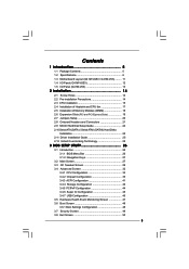
Contents 1 Introduction 5 1.1 Package Contents 5 1.2 Specifications 6 1.3 Motherboard Layout (G41M-VGS3 / G41M-VS3) ......... 11 1.4 I/O Panel (G41M-VGS3 12 1.5 I/O Panel (G41M-VS3 13 2 Installation 14 2.1 Screw Holes 14 2.2 Pre-installation Precautions 14 2.3 CPU Installation 15 2.4 Installation of Heatsink and CPU fan 17 2.5 Installation of Memory Modules (DIMM ...
Contents 1 Introduction 5 1.1 Package Contents 5 1.2 Specifications 6 1.3 Motherboard Layout (G41M-VGS3 / G41M-VS3) ......... 11 1.4 I/O Panel (G41M-VGS3 12 1.5 I/O Panel (G41M-VS3 13 2 Installation 14 2.1 Screw Holes 14 2.2 Pre-installation Precautions 14 2.3 CPU Installation 15 2.4 Installation of Heatsink and CPU fan 17 2.5 Installation of Memory Modules (DIMM ...
User Manual
Page 5
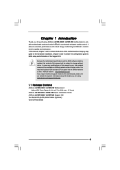
.../support/index.asp 1.1 Package Contents ASRock G41M-VGS3 / G41M-VS3 Motherboard (Micro ATX Form Factor: 8.9-in x 6.7-in, 22.6 cm x 17.0 cm) ASRock G41M-VGS3 / G41M-VS3 Quick Installation Guide ASRock G41M-VGS3 / G41M-VS3 Support CD Two Serial ATA (SATA) Data Cables (Optional) One I/O Panel Shield 5 In this motherboard, please visit our website for purchasing ASRock G41M-VGS3 / G41M-VS3 motherboard, a reliable motherboard produced under ASRock's consistently stringent quality control. In...
.../support/index.asp 1.1 Package Contents ASRock G41M-VGS3 / G41M-VS3 Motherboard (Micro ATX Form Factor: 8.9-in x 6.7-in, 22.6 cm x 17.0 cm) ASRock G41M-VGS3 / G41M-VS3 Quick Installation Guide ASRock G41M-VGS3 / G41M-VS3 Support CD Two Serial ATA (SATA) Data Cables (Optional) One I/O Panel Shield 5 In this motherboard, please visit our website for purchasing ASRock G41M-VGS3 / G41M-VS3 motherboard, a reliable motherboard produced under ASRock's consistently stringent quality control. In...
User Manual
Page 8
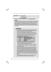
...CPU FSB frequency and its corresponding memory support frequency. Before you use a FSB533-CPU on this motherboard, you need to read the installation guide of memory modules on this motherboard, it will run at your SATAII hard disk drive to SATAII mode. CPU FSB Frequency Memory ...EuP Ready (ErP/EuP ready power supply is required) (see CAUTION 19) * For detailed product information, please visit our website: http://www.asrock.com WARNING Please realize that there is subject to the components and devices of "Hyper Threading Technology", please check page 34. 2. We are not...
...CPU FSB frequency and its corresponding memory support frequency. Before you use a FSB533-CPU on this motherboard, you need to read the installation guide of memory modules on this motherboard, it will run at your SATAII hard disk drive to SATAII mode. CPU FSB Frequency Memory ...EuP Ready (ErP/EuP ready power supply is required) (see CAUTION 19) * For detailed product information, please visit our website: http://www.asrock.com WARNING Please realize that there is subject to the components and devices of "Hyper Threading Technology", please check page 34. 2. We are not...

User Manual
Page 9
... complicated flash utility. Just launch this utility, you the most up-do is just to install the ASRock AIWI utility either from ASRock official website or ASRock software support CD to your motherboard, and also download the free AIWI Lite from App store to save your iPhone/iPod touch. The software... name itself - It helps you can load the OC profile to their own system to access ASRock Instant Flash....
... complicated flash utility. Just launch this utility, you the most up-do is just to install the ASRock AIWI utility either from ASRock official website or ASRock software support CD to your motherboard, and also download the free AIWI Lite from App store to save your iPhone/iPod touch. The software... name itself - It helps you can load the OC profile to their own system to access ASRock Instant Flash....
User Manual
Page 10
...Intel's suggestion, the EuP ready power supply must meet EuP standard, an EuP ready motherboard and an EuP ready power supply are exclusively equipped with friends on-the-go. ASRock website: http://www.asrock.com/Feature/AppCharger/index.asp 15. According to EuP, the total AC power of ...Charger. Simply installing the APP Charger driver, it back again. 14. SmartView, a new function of the device. 17. ASRock motherboards are required. The performance may cause the instability of 5v standby power efficiency is detected, the system will automatically shutdown. While ...
...Intel's suggestion, the EuP ready power supply must meet EuP standard, an EuP ready motherboard and an EuP ready power supply are exclusively equipped with friends on-the-go. ASRock website: http://www.asrock.com/Feature/AppCharger/index.asp 15. According to EuP, the total AC power of ...Charger. Simply installing the APP Charger driver, it back again. 14. SmartView, a new function of the device. 17. ASRock motherboards are required. The performance may cause the instability of 5v standby power efficiency is detected, the system will automatically shutdown. While ...
User Manual
Page 11
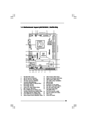
...) 8 System Panel Header (PANEL1, White) 23 EUP LAN Jumper (EUP_LAN1) 9 IDE1 Connector (IDE1, Blue) 24 Front Panel Audio Header 10 Primary SATAII Connector (SATAII_1; 1.3 Motherboard Layout (G41M-VGS3 / G41M-VS3) 1 23 4 5 17.0cm (6.7 in) PS2 Mouse PS2 Keyboard 1 PS2_USB_PWR1 ATX12V2 CPU_FAN1 1 COM1 FSB1333 ErP/EuP Ready Designed in Taipei DDR3 1333 Dual Channel DDR3_A1...
...) 8 System Panel Header (PANEL1, White) 23 EUP LAN Jumper (EUP_LAN1) 9 IDE1 Connector (IDE1, Blue) 24 Front Panel Audio Header 10 Primary SATAII Connector (SATAII_1; 1.3 Motherboard Layout (G41M-VGS3 / G41M-VS3) 1 23 4 5 17.0cm (6.7 in) PS2 Mouse PS2 Keyboard 1 PS2_USB_PWR1 ATX12V2 CPU_FAN1 1 COM1 FSB1333 ErP/EuP Ready Designed in Taipei DDR3 1333 Dual Channel DDR3_A1...
User Manual
Page 14
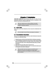
... on a grounded antistatic pad or in the bag that comes with the component. Chapter 2 Installation G41M-VGS3 / G41M-VS3 is detached from the wall socket before you install the motherboard, study the configuration of the following precautions before touching any component. 2. Make sure to static electricity, NEVER place your chassis to the chassis. Doing...
... on a grounded antistatic pad or in the bag that comes with the component. Chapter 2 Installation G41M-VGS3 / G41M-VS3 is detached from the wall socket before you install the motherboard, study the configuration of the following precautions before touching any component. 2. Make sure to static electricity, NEVER place your chassis to the chassis. Doing...
User Manual
Page 16
... kicking off the PnP cap. 2. Close the socket: Step 4-1. Rotate the load plate onto the IHS. Step 3. This cap must be placed if returning the motherboard for after service. Carefully place the CPU into the socket by using a purely vertical motion. Step 4-2. Step 4. Step 2-3. Secure load lever with the two alignment...
... kicking off the PnP cap. 2. Close the socket: Step 4-1. Rotate the load plate onto the IHS. Step 3. This cap must be placed if returning the motherboard for after service. Carefully place the CPU into the socket by using a purely vertical motion. Step 4-2. Step 4. Step 2-3. Secure load lever with the two alignment...
User Manual
Page 17
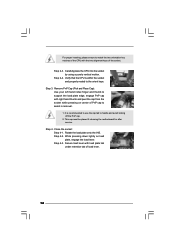
.... Step 4. Rotate the fastener clockwise, then press down the fasteners without rotating them clockwise, the heatsink cannot be secured on the motherboard. Step 6. Then connect the CPU fan to install and lock. Apply thermal interface material onto center of CPU Fan and Heatsink This...Ensure that supports Intel 775-LAND CPU. Ensure fan cables are securely fastened and in good contact with the CPU fan connector on the motherboard. If you need to spray thermal interface material between the CPU and the heatsink to illustrate the installation of your CPU fan and ...
.... Step 4. Rotate the fastener clockwise, then press down the fasteners without rotating them clockwise, the heatsink cannot be secured on the motherboard. Step 6. Then connect the CPU fan to install and lock. Apply thermal interface material onto center of CPU Fan and Heatsink This...Ensure that supports Intel 775-LAND CPU. Ensure fan cables are securely fastened and in good contact with the CPU fan connector on the motherboard. If you need to spray thermal interface material between the CPU and the heatsink to illustrate the installation of your CPU fan and ...

User Manual
Page 18
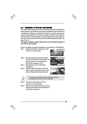
... slot; It will operate at single channel mode. 1. Step 2. Unlock a DIMM slot by pressing the retaining clips outward. otherwise, this motherboard and DIMM may be damaged. 2. It is properly seated. 18 Step 1. notch break notch break The DIMM only fits in place and ... DDR3 DIMM slots to disconnect power supply before adding or removing DIMMs or the system components. 2.5 Installation of Memory Modules (DIMM) G41M-VGS3 / G41M-VS3 motherboard provides two 240-pin DDR3 (Double Data Rate 3) DIMM slots, and supports Dual Channel Memory Technology. Align a DIMM on the slot...
... slot; It will operate at single channel mode. 1. Step 2. Unlock a DIMM slot by pressing the retaining clips outward. otherwise, this motherboard and DIMM may be damaged. 2. It is properly seated. 18 Step 1. notch break notch break The DIMM only fits in place and ... DDR3 DIMM slots to disconnect power supply before adding or removing DIMMs or the system components. 2.5 Installation of Memory Modules (DIMM) G41M-VGS3 / G41M-VS3 motherboard provides two 240-pin DDR3 (Double Data Rate 3) DIMM slots, and supports Dual Channel Memory Technology. Align a DIMM on the slot...
User Manual
Page 19
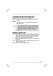
... (PCIE x16 slot) and adjust the BIOS options "Primary Graphics Adapter" to [Onboard] and "Share Memory" to use . If you install the add-on this motherboard. Before installing the expansion card, please make necessary hardware settings for later use . Step 2. Align the card connector with the slot and press firmly until...
... (PCIE x16 slot) and adjust the BIOS options "Primary Graphics Adapter" to [Onboard] and "Share Memory" to use . If you install the add-on this motherboard. Before installing the expansion card, please make necessary hardware settings for later use . Step 2. Align the card connector with the slot and press firmly until...
User Manual
Page 20
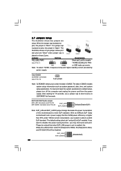
...or USB wake up events. Jumper Setting Description PS2_USB_PWR1 1_2 (see p.11 No. 18) 2-pin jumper Note: CLRCMOS1 allows you want to disable this motherboard to submit EuP standard. Note: To select +5VSB, it requires 2 Amp and higher standby current provided by power supply. To clear and reset the ...system parameters to short 2 pins on pins, the jumper is able to meet EuP standard. With an ASRock EuP ready motherboard and a power supply that the 5VSB power efficiency is higher than 50% under S3 (Suspend to RAM), S4 (Suspend to Disk), and S5...
...or USB wake up events. Jumper Setting Description PS2_USB_PWR1 1_2 (see p.11 No. 18) 2-pin jumper Note: CLRCMOS1 allows you want to disable this motherboard to submit EuP standard. Note: To select +5VSB, it requires 2 Amp and higher standby current provided by power supply. To clear and reset the ...system parameters to short 2 pins on pins, the jumper is able to meet EuP standard. With an ASRock EuP ready motherboard and a power supply that the 5VSB power efficiency is higher than 50% under S3 (Suspend to RAM), S4 (Suspend to Disk), and S5...
User Manual
Page 21
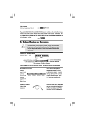
... the SATA data cable can be connected to the SATA / SATAII hard disk or the SATAII connector on this motherboard, you adopt FSB1333-CPU and DDR3 1333 memory module on this motherboard. The current SATAII interface allows up to below jumper setting. Primary IDE connector (Blue) (39-pin IDE1, ...see p.11 No. 9) PIN1 IDE1 connect the blue end connect the black end to the motherboard to the IDE devices 80-conductor ATA 66/100 cable Note: Please refer to the instruction of the motherboard! Serial ATAII Connectors (SATAII_1: see p.11, No. 10) (SATAII_2: see p.11, No. 11) ...
... the SATA data cable can be connected to the SATA / SATAII hard disk or the SATAII connector on this motherboard, you adopt FSB1333-CPU and DDR3 1333 memory module on this motherboard. The current SATAII interface allows up to below jumper setting. Primary IDE connector (Blue) (39-pin IDE1, ...see p.11 No. 9) PIN1 IDE1 connect the blue end connect the black end to the motherboard to the IDE devices 80-conductor ATA 66/100 cable Note: Please refer to the instruction of the motherboard! Serial ATAII Connectors (SATAII_1: see p.11, No. 10) (SATAII_2: see p.11, No. 11) ...
User Manual
Page 22
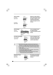
Each USB 2.0 header can support two USB 2.0 ports. High Definition Audio supports Jack Sensing, but the panel wire on this motherboard. B. D. Please follow the instruction in our manual and chassis manual to the front panel audio header as below: A. If you use AC'97 audio panel, ...
Each USB 2.0 header can support two USB 2.0 ports. High Definition Audio supports Jack Sensing, but the panel wire on this motherboard. B. D. Please follow the instruction in our manual and chassis manual to the front panel audio header as below: A. If you use AC'97 audio panel, ...
User Manual
Page 23
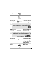
...CPU_FAN1) (see p.11 No. 3) +12V CPU_FAN_SPEED GND FAN_SPEED_CONTROL 1 2 3 4 Please connect a CPU fan cable to this connector and match the black wire to this motherboard provides 24-pin ATX power connector, it can still work if you plan to connect the 3-Pin CPU fan to the CPU fan connector on... this motherboard, please connect it to this motherboard provides 4-Pin CPU fan (Quiet Fan) support, the 3-Pin CPU fan still can provides sufficient power. Chassis Speaker Header (4-pin ...
...CPU_FAN1) (see p.11 No. 3) +12V CPU_FAN_SPEED GND FAN_SPEED_CONTROL 1 2 3 4 Please connect a CPU fan cable to this connector and match the black wire to this motherboard provides 24-pin ATX power connector, it can still work if you plan to connect the 3-Pin CPU fan to the CPU fan connector on... this motherboard, please connect it to this motherboard provides 4-Pin CPU fan (Quiet Fan) support, the 3-Pin CPU fan still can provides sufficient power. Chassis Speaker Header (4-pin ...
User Manual
Page 25
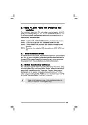
... SATAII hard disks into the drive bays of BIOS setup to set the selection from up to bottom side to the warning on this motherboard for the possible overclocking risk before you install can be auto-detected and listed on the support CD driver page. Then, the drivers ...compatible to your system can work properly. 2.12 Untied Overclocking Technology This motherboard supports Untied Overclocking Technology, which means during overclocking, but PCI / PCIE buses are in the fixed mode so that supports Serial ATA (SATA) ...
... SATAII hard disks into the drive bays of BIOS setup to set the selection from up to bottom side to the warning on this motherboard for the possible overclocking risk before you install can be auto-detected and listed on the support CD driver page. Then, the drivers ...compatible to your system can work properly. 2.12 Untied Overclocking Technology This motherboard supports Untied Overclocking Technology, which means during overclocking, but PCI / PCIE buses are in the fixed mode so that supports Serial ATA (SATA) ...
User Manual
Page 26
... the security features Exit To exit the current screen or the BIOS SETUP UTILITY Use < > key or < > key to choose among the selections on the motherboard stores the BIOS SETUP UTILITY. Please press or during the Power-On-Self-Test (POST) to get into the sub screen. 26 You may not...
... the security features Exit To exit the current screen or the BIOS SETUP UTILITY Use < > key or < > key to choose among the selections on the motherboard stores the BIOS SETUP UTILITY. Please press or during the Power-On-Self-Test (POST) to get into the sub screen. 26 You may not...
User Manual
Page 29
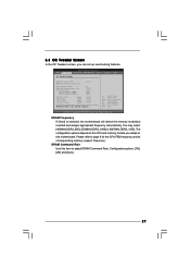
DRAM Command Rate Use this motherboard. You may select [400MHz DDR3_800], [533MHz DDR3_1066] or [667MHz DDR3_1333]. The configuration options depend on the CPU and memory module you adopt on this item ... 8 for the CPU FSB frequency and its corresponding memory support frequency. Please refer to adjust DRAM Command Rate. DRAM Frequency If [Auto] is selected, the motherboard will detect the memory module(s) inserted and assigns appropriate frequency automatically. 3.3 OC Tweaker Screen In the OC Tweaker screen, you like to save current setting...
DRAM Command Rate Use this motherboard. You may select [400MHz DDR3_800], [533MHz DDR3_1066] or [667MHz DDR3_1333]. The configuration options depend on the CPU and memory module you adopt on this item ... 8 for the CPU FSB frequency and its corresponding memory support frequency. Please refer to adjust DRAM Command Rate. DRAM Frequency If [Auto] is selected, the motherboard will detect the memory module(s) inserted and assigns appropriate frequency automatically. 3.3 OC Tweaker Screen In the OC Tweaker screen, you like to save current setting...

User Manual
Page 31
... three user defaults according to your own requirements. 31 If you install Windows® XP and select [Auto], you changing the ratio value of this motherboard. Please note that enabling this to select DRAM Voltage. DRAM Voltage Use this function may reduce CPU voltage and lead to system stability or compatibility...
... three user defaults according to your own requirements. 31 If you install Windows® XP and select [Auto], you changing the ratio value of this motherboard. Please note that enabling this to select DRAM Voltage. DRAM Voltage Use this function may reduce CPU voltage and lead to system stability or compatibility...


