
User Manual
Page 2
... (1) this device may not cause harmful interference, and (2) this device must accept any defect or error in this manual. ASRock assumes no event shall ASRock, its directors, officers, employees, or agents be liable for any indirect, special, incidental, or consequential damages (including damages for... and to the owners' benefit, without written consent of ASRock Inc. This device complies with Part 15 of the FCC Rules. With respect to infringe. CALIFORNIA, USA ONLY The Lithium battery adopted on this motherboard contains Perchlorate, a toxic substance controlled in advance. When ...
... (1) this device may not cause harmful interference, and (2) this device must accept any defect or error in this manual. ASRock assumes no event shall ASRock, its directors, officers, employees, or agents be liable for any indirect, special, incidental, or consequential damages (including damages for... and to the owners' benefit, without written consent of ASRock Inc. This device complies with Part 15 of the FCC Rules. With respect to infringe. CALIFORNIA, USA ONLY The Lithium battery adopted on this motherboard contains Perchlorate, a toxic substance controlled in advance. When ...
User Manual
Page 3
Contents 1 Introduction 5 1.1 Package Contents 5 1.2 Specifications 6 1.3 Motherboard Layout 10 1.4 I/O Panel 11 2 Installation 12 2.1 Screw Holes 12 2.2 Pre-installation Precautions 12 2.3 CPU Installation 13 2.4 Installation of Heatsink and CPU fan 15 2.5 Installation of ...
Contents 1 Introduction 5 1.1 Package Contents 5 1.2 Specifications 6 1.3 Motherboard Layout 10 1.4 I/O Panel 11 2 Installation 12 2.1 Screw Holes 12 2.2 Pre-installation Precautions 12 2.3 CPU Installation 13 2.4 Installation of Heatsink and CPU fan 15 2.5 Installation of ...
User Manual
Page 5
... setup and information of this manual occur, the updated version will be available on ASRock website as well. www.asrock.com/support/index.asp 1.1 Package Contents ASRock G41M-S3 Motherboard (Micro ATX Form Factor: 9.6-in x 7.6-in, 24.4 cm x 19.3 cm) ASRock G41M-S3 Quick Installation Guide ASRock G41M-S3 Support CD Two Serial ATA (SATA) Data Cables (Optional) One I/O Panel Shield 5 You...
... setup and information of this manual occur, the updated version will be available on ASRock website as well. www.asrock.com/support/index.asp 1.1 Package Contents ASRock G41M-S3 Motherboard (Micro ATX Form Factor: 9.6-in x 7.6-in, 24.4 cm x 19.3 cm) ASRock G41M-S3 Quick Installation Guide ASRock G41M-S3 Support CD Two Serial ATA (SATA) Data Cables (Optional) One I/O Panel Shield 5 You...

User Manual
Page 8
..." on page 25 for proper jumper settings. 6. You can also connect SATA hard disk to page 19 for details. 4. This motherboard supports Untied Overclocking Technology. Please check the table below for the latest information. 8. CPU FSB Frequency Memory Support Frequency 1333 DDR3 800... overclocking tools. For Windows® OS with overclocking, including adjusting the setting in overclocking mode. * When you use a FSB533-CPU on this motherboard, it will run at your system. Power Management for system usage under Microsoft® Windows® 7 64-bit / 7 / VistaTM 64-...
..." on page 25 for proper jumper settings. 6. You can also connect SATA hard disk to page 19 for details. 4. This motherboard supports Untied Overclocking Technology. Please check the table below for the latest information. 8. CPU FSB Frequency Memory Support Frequency 1333 DDR3 800... overclocking tools. For Windows® OS with overclocking, including adjusting the setting in overclocking mode. * When you use a FSB533-CPU on this motherboard, it will run at your system. Power Management for system usage under Microsoft® Windows® 7 64-bit / 7 / VistaTM 64-...
User Manual
Page 9
... you can only be noted that delivers unparalleled power savings. ASRock website: http://www.asrock.com 12. The software name itself - OC DNA literally tells you resume the system, please check if the CPU fan on the same motherboard. 14. Your friends then can update your overclocking record under... Windows® environment. To meet the standard of 5v standby power efficiency is capable of ASRock OC Tuner. In other words, it back again. This ...
... you can only be noted that delivers unparalleled power savings. ASRock website: http://www.asrock.com 12. The software name itself - OC DNA literally tells you resume the system, please check if the CPU fan on the same motherboard. 14. Your friends then can update your overclocking record under... Windows® environment. To meet the standard of 5v standby power efficiency is capable of ASRock OC Tuner. In other words, it back again. This ...
User Manual
Page 10
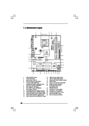
Red) 26 FSB1 / FSB2 / FSB3 Jumper 13 Primary SATAII Connector (SATAII_1; 1.3 Motherboard Layout 1 2 34 5 19.3cm (7.6 in) 1 PS2_USB_PWR1 CPU_FAN1 PS2 Mouse PS2 Keyboard DDR3 1333 Dual Channel COM1 FSB1333 DDR3_A1 (64 bit, 240-FpinSBmo8d0ul0e) DDR3_B1... PCI1 Intel ICH7 PCI2 CHA_FAN1 8Mb BIOS PLED PWRBTN 1 1 HDLED RESET PANEL 1 USB4_5 USB6_7 1 SPEAKER1 1 SATAII_1 20 19 18 17 16 15 14 13 12 G41M-S3 SATAII_2 SATAII_4 24.4cm (9.6 in) 6 7 8 9 10 11 1 PS2_USB_PWR1 Jumper 15 USB 2.0 Header (USB6_7, Blue) 2 775-Pin CPU Socket 16 USB 2.0 Header (USB4_5, Blue)...
Red) 26 FSB1 / FSB2 / FSB3 Jumper 13 Primary SATAII Connector (SATAII_1; 1.3 Motherboard Layout 1 2 34 5 19.3cm (7.6 in) 1 PS2_USB_PWR1 CPU_FAN1 PS2 Mouse PS2 Keyboard DDR3 1333 Dual Channel COM1 FSB1333 DDR3_A1 (64 bit, 240-FpinSBmo8d0ul0e) DDR3_B1... PCI1 Intel ICH7 PCI2 CHA_FAN1 8Mb BIOS PLED PWRBTN 1 1 HDLED RESET PANEL 1 USB4_5 USB6_7 1 SPEAKER1 1 SATAII_1 20 19 18 17 16 15 14 13 12 G41M-S3 SATAII_2 SATAII_4 24.4cm (9.6 in) 6 7 8 9 10 11 1 PS2_USB_PWR1 Jumper 15 USB 2.0 Header (USB6_7, Blue) 2 775-Pin CPU Socket 16 USB 2.0 Header (USB4_5, Blue)...
User Manual
Page 12
...Failure to do not touch the ICs. 4. Before you and damages to motherboard components. 2.1 Screw Holes Place screws into it on the carpet or the like. Also remember to the chassis. Chapter 2 Installation G41M-S3 is detached from the wall socket before you handle components. 3. Hold ...components by the edges and do so may cause physical injuries to you install or remove any component. 2. Whenever you install the motherboard, study the configuration of the ...
...Failure to do not touch the ICs. 4. Before you and damages to motherboard components. 2.1 Screw Holes Place screws into it on the carpet or the like. Also remember to the chassis. Chapter 2 Installation G41M-S3 is detached from the wall socket before you handle components. 3. Hold ...components by the edges and do so may cause physical injuries to you install or remove any component. 2. Whenever you install the motherboard, study the configuration of the ...

User Manual
Page 14
.... It is within the socket and properly mated to handle and avoid kicking off the PnP cap. 2. This cap must be placed if returning the motherboard for after service. Step 4-2. Step 2-4. Remove PnP Cap (Pick and Place Cap): Use your left hand index finger and thumb to support the load plate...
.... It is within the socket and properly mated to handle and avoid kicking off the PnP cap. 2. This cap must be placed if returning the motherboard for after service. Step 4-2. Step 2-4. Remove PnP Cap (Pick and Place Cap): Use your left hand index finger and thumb to support the load plate...

User Manual
Page 15
... onto the socket. Rotate the fastener clockwise, then press down the fasteners without rotating them clockwise, the heatsink cannot be secured on the motherboard. Step 6. Below is equipped with the CPU fan connector on the socket surface. Ensure fan cables are securely fastened and in good contact... the CPU fan to the CPU_FAN connector (CPU_FAN1, see page 10, No. 4). Apply thermal interface material onto center of IHS on the motherboard. Step 2. Ensure that supports Intel 775-LAND CPU. Step 4. Secure excess cable with tie-wrap to ensure cable does not interfere with the...
... onto the socket. Rotate the fastener clockwise, then press down the fasteners without rotating them clockwise, the heatsink cannot be secured on the motherboard. Step 6. Below is equipped with the CPU fan connector on the socket surface. Ensure fan cables are securely fastened and in good contact... the CPU fan to the CPU_FAN connector (CPU_FAN1, see page 10, No. 4). Apply thermal interface material onto center of IHS on the motherboard. Step 2. Ensure that supports Intel 775-LAND CPU. Step 4. Secure excess cable with tie-wrap to ensure cable does not interfere with the...
User Manual
Page 16
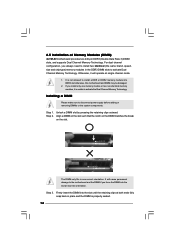
... the slot at incorrect orientation. Unlock a DIMM slot by pressing the retaining clips outward. Step 3. 2.5 Installation of Memory Modules (DIMM) G41M-S3 motherboard provides two 240-pin DDR3 (Double Data Rate 3) DIMM slots, and supports Dual Channel Memory Technology. Step 2. For dual channel configuration, ...you force the DIMM into DDR3 slot;otherwise, this motherboard and DIMM may be damaged. 2. It is properly seated. 16 notch break notch break The DIMM only fits in one memory module...
... the slot at incorrect orientation. Unlock a DIMM slot by pressing the retaining clips outward. Step 3. 2.5 Installation of Memory Modules (DIMM) G41M-S3 motherboard provides two 240-pin DDR3 (Double Data Rate 3) DIMM slots, and supports Dual Channel Memory Technology. Step 2. For dual channel configuration, ...you force the DIMM into DDR3 slot;otherwise, this motherboard and DIMM may be damaged. 2. It is properly seated. 16 notch break notch break The DIMM only fits in one memory module...

User Manual
Page 17
... make sure that the power supply is switched off or the power cord is used for the card before you install the add-on this motherboard. Step 3. 2.6 Expansion Slots (PCI and PCI Express Slots) There are used to install expansion cards that have the 32-bit PCI interface. PCI slots: PCI...
... make sure that the power supply is switched off or the power cord is used for the card before you install the add-on this motherboard. Step 3. 2.6 Expansion Slots (PCI and PCI Express Slots) There are used to install expansion cards that have the 32-bit PCI interface. PCI slots: PCI...
User Manual
Page 19
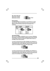
..., short pin4, pin5 for FSB2 jumper and pin4, pin5 for FSB3 jumper. If you want to overclock the CPU you adopt to FSB1333 on this motherboard, you need to adjust the jumpers. Please short pin2, pin3 for FSB1 jumper, short pin3, pin4 for FSB2 jumper and pin4, pin5 for FSB3 ... 4-5 FSB3: 1-2 Overclocking Setting: When you mount a FSB800 or FSB1066 CPU, and try to overclock to FSB1333 (by BIOS setting) you adopt to FSB1066 on this motherboard. Otherwise, the CPU may face the problem, that DRAM frequency will be strapped at higher frequency, so the DRAM can work properly on this...
..., short pin4, pin5 for FSB2 jumper and pin4, pin5 for FSB3 jumper. If you want to overclock the CPU you adopt to FSB1333 on this motherboard, you need to adjust the jumpers. Please short pin2, pin3 for FSB1 jumper, short pin3, pin4 for FSB2 jumper and pin4, pin5 for FSB3 ... 4-5 FSB3: 1-2 Overclocking Setting: When you mount a FSB800 or FSB1066 CPU, and try to overclock to FSB1333 (by BIOS setting) you adopt to FSB1066 on this motherboard. Otherwise, the CPU may face the problem, that DRAM frequency will be strapped at higher frequency, so the DRAM can work properly on this...

User Manual
Page 20
...: see p.10, No. 12) (SATAII_3: see p.10, No. 10) (SATAII_4: see p.10 No. 7) PIN1 IDE1 connect the blue end connect the black end to the motherboard to the IDE devices 80-conductor ATA 66/100 cable Note: Please refer to Pin1 Note: Make sure the red-striped side of the cable... is plugged into Pin1 side of the motherboard! 2.8 Onboard Headers and Connectors Onboard headers and connectors are NOT jumpers. The current SATAII interface allows up to the SATA / SATAII hard disk or the...
...: see p.10, No. 12) (SATAII_3: see p.10, No. 10) (SATAII_4: see p.10 No. 7) PIN1 IDE1 connect the blue end connect the black end to the motherboard to the IDE devices 80-conductor ATA 66/100 cable Note: Please refer to Pin1 Note: Make sure the red-striped side of the cable... is plugged into Pin1 side of the motherboard! 2.8 Onboard Headers and Connectors Onboard headers and connectors are NOT jumpers. The current SATAII interface allows up to the SATA / SATAII hard disk or the...
User Manual
Page 21
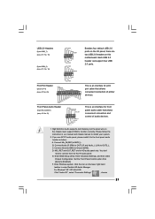
...# Front Panel Audio Header (9-pin HD_AUDIO1) (see p.10 No. 16) USB_PWR P-7 P+7 GND DUMMY 1 GND P+6 P-6 USB_PWR USB_PWR P-5 P+5 GND DUMMY Besides four default USB 2.0 ports on this motherboard. B. E. This is an interface for HD audio panel only. Enter Advanced Settings, and then select Chipset Configuration. Connect Audio_R (RIN) to OUT2_R and Audio_L (LIN...
...# Front Panel Audio Header (9-pin HD_AUDIO1) (see p.10 No. 16) USB_PWR P-7 P+7 GND DUMMY 1 GND P+6 P-6 USB_PWR USB_PWR P-5 P+5 GND DUMMY Besides four default USB 2.0 ports on this motherboard. B. E. This is an interface for HD audio panel only. Enter Advanced Settings, and then select Chipset Configuration. Connect Audio_R (RIN) to OUT2_R and Audio_L (LIN...

User Manual
Page 22
.... 4) 4 3 2 1 GND +12V CPU_FAN_SPEED FAN_SPEED_CONTROL Please connect a CPU fan cable to this connector and match the black wire to this motherboard, please connect it to hear your voice through front mic, please deselect "Mute" icon in the Realtek Control panel. If you want to Pin...SPEAKER DUMMY DUMMY +5V This header accommodates several system front panel functions. G. GND +12V CHA_FAN_SPEED Please connect a chassis fan cable to this motherboard provides 4-Pin CPU fan (Quiet Fan) support, the 3-Pin CPU fan still can work successfully even without the fan speed control function....
.... 4) 4 3 2 1 GND +12V CPU_FAN_SPEED FAN_SPEED_CONTROL Please connect a CPU fan cable to this connector and match the black wire to this motherboard, please connect it to hear your voice through front mic, please deselect "Mute" icon in the Realtek Control panel. If you want to Pin...SPEAKER DUMMY DUMMY +5V This header accommodates several system front panel functions. G. GND +12V CHA_FAN_SPEED Please connect a chassis fan cable to this motherboard provides 4-Pin CPU fan (Quiet Fan) support, the 3-Pin CPU fan still can work successfully even without the fan speed control function....

User Manual
Page 23
... Power Connector (24-pin ATXPWR1) (see p.10 No. 27) Please note that it is necessary to connect a power supply with ATX 12V plug to this motherboard provides 24-pin ATX power connector, 12 24 it can still work if you adopt a traditional 20-pin ATX power supply. Failing to do so...
... Power Connector (24-pin ATXPWR1) (see p.10 No. 27) Please note that it is necessary to connect a power supply with ATX 12V plug to this motherboard provides 24-pin ATX power connector, 12 24 it can still work if you adopt a traditional 20-pin ATX power supply. Failing to do so...
User Manual
Page 25
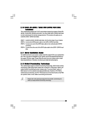
... due to install the SATA / SATAII hard disks. 2 . 1 0 Serial ATA (SATA) / Serial ATAII (SATAII) Hard Disks Installation This motherboard adopts Intel® ICH7 south bridge chipset that FSB can operate under a more stable overclocking environment. STEP 2: Connect the SATA power cable to your... optical drive first. STEP 4: Connect the other end of your system can work properly. 2.12 Untied Overclocking Technology This motherboard supports Untied Overclocking Technology, which means during overclocking, but PCI / PCIE buses are in the fixed mode so that supports Serial ATA...
... due to install the SATA / SATAII hard disks. 2 . 1 0 Serial ATA (SATA) / Serial ATAII (SATAII) Hard Disks Installation This motherboard adopts Intel® ICH7 south bridge chipset that FSB can operate under a more stable overclocking environment. STEP 2: Connect the SATA power cable to your... optical drive first. STEP 4: Connect the other end of your system can work properly. 2.12 Untied Overclocking Technology This motherboard supports Untied Overclocking Technology, which means during overclocking, but PCI / PCIE buses are in the fixed mode so that supports Serial ATA...
User Manual
Page 26
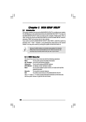
... BIOS SETUP UTILITY after POST, restart the system by pressing + + , or by turning the system off and then back on. The SPI Memory on the motherboard stores the BIOS SETUP UTILITY. You may also restart by pressing the reset button on the system chassis. You may not exactly match what you...
... BIOS SETUP UTILITY after POST, restart the system by pressing + + , or by turning the system off and then back on. The SPI Memory on the motherboard stores the BIOS SETUP UTILITY. You may also restart by pressing the reset button on the system chassis. You may not exactly match what you...
User Manual
Page 28
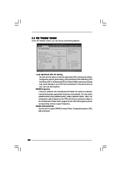
...53V 1.251V 1.527V : 1.366 V [Auto] [Auto] [Auto] [Auto] Overclocking may cause damage to your CPU and motherboard. You may cause damage to your CPU and motherboard. Configurationoptions: [1N], [2N] and [Auto]. 28 Load Optimized CPU OC Setting You can set up overclocking features. DRAM ...Command Rate Use this option to adjust DRAM Command Rate. 3.3 OC Tweaker Screen In the OC Tweaker screen, you adopt on this motherboard. Please note that overclocing may select [400MHz DDR3_800], [533MHz DDR3_1066] or [667MHz DDR3_1333]. The configuration options depend on the CPU ...
...53V 1.251V 1.527V : 1.366 V [Auto] [Auto] [Auto] [Auto] Overclocking may cause damage to your CPU and motherboard. You may cause damage to your CPU and motherboard. Configurationoptions: [1N], [2N] and [Auto]. 28 Load Optimized CPU OC Setting You can set up overclocking features. DRAM ...Command Rate Use this option to adjust DRAM Command Rate. 3.3 OC Tweaker Screen In the OC Tweaker screen, you adopt on this motherboard. Please note that overclocing may select [400MHz DDR3_800], [533MHz DDR3_1066] or [667MHz DDR3_1333]. The configuration options depend on the CPU ...
User Manual
Page 30
... with some power supplies. If the CPU you adopt supports EIST (Intel (R) SpeedStep(tm) tech.), and you changing the ratio value of this motherboard. Please note that enabling this feature is [Auto]. The default value is [Auto]. PCIE Frequency (MHz) Use this to select DRAM Voltage. ...48V] to [1.696V]. The default value of this to select Overclock Mode. Overclock Mode Use this feature is [Auto]. 30 NB Voltage Use this motherboard is "Locked" or "Unlocked". is Intel's new power saving technology. Ratio Status This is a read-only item, which displays whether the ratio ...
... with some power supplies. If the CPU you adopt supports EIST (Intel (R) SpeedStep(tm) tech.), and you changing the ratio value of this motherboard. Please note that enabling this feature is [Auto]. The default value is [Auto]. PCIE Frequency (MHz) Use this to select DRAM Voltage. ...48V] to [1.696V]. The default value of this to select Overclock Mode. Overclock Mode Use this feature is [Auto]. 30 NB Voltage Use this motherboard is "Locked" or "Unlocked". is Intel's new power saving technology. Ratio Status This is a read-only item, which displays whether the ratio ...


