
User Manual
Page 2
... Best Management Practices (BMP) regulations passed by the California Legislature. Disclaimer: Specifications and information contained in advance. ASRock assumes no event shall ASRock, its directors, officers, employees, or agents be liable for any indirect, special, incidental, or consequential damages ...this device may not cause harmful interference, and (2) this manual. CALIFORNIA, USA ONLY The Lithium battery adopted on this motherboard contains Perchlorate, a toxic substance controlled in this device must accept any errors or omissions that may cause undesired operation. Products...
... Best Management Practices (BMP) regulations passed by the California Legislature. Disclaimer: Specifications and information contained in advance. ASRock assumes no event shall ASRock, its directors, officers, employees, or agents be liable for any indirect, special, incidental, or consequential damages ...this device may not cause harmful interference, and (2) this manual. CALIFORNIA, USA ONLY The Lithium battery adopted on this motherboard contains Perchlorate, a toxic substance controlled in this device must accept any errors or omissions that may cause undesired operation. Products...

User Manual
Page 3
... for Full HD 1080p Blu-ray (BD) / HD-DVD Playback Support ...1.4 Passed Full HD 1080p Blu-ray (BD) / HD-DVD Films in Our Lab Test ...1.5 Motherboard Layout ...1.6 I/O Panel ...5 6 10 10 11 12 2 Installation ...13 2.1 Screw Holes ...13 2.2 Pre-installation Precautions ...13 2.3 CPU Installation ...14 2.4 Installation of Heatsink and CPU fan ...16...
... for Full HD 1080p Blu-ray (BD) / HD-DVD Playback Support ...1.4 Passed Full HD 1080p Blu-ray (BD) / HD-DVD Films in Our Lab Test ...1.5 Motherboard Layout ...1.6 I/O Panel ...5 6 10 10 11 12 2 Installation ...13 2.1 Screw Holes ...13 2.2 Pre-installation Precautions ...13 2.3 CPU Installation ...14 2.4 Installation of Heatsink and CPU fan ...16...
User Manual
Page 5
... guide to BIOS setup and information of this motherboard, please visit our website for purchasing ASRock G41M-LE motherboard, a reliable motherboard produced under ASRock's consistently stringent quality control. www.asrock.com/support/index.asp 1.1 P ack age Contents ackage ASRock G41M-LE Motherboard (Micro ATX Form Factor: 9.6-in x 8.6-in, 24.4 cm x 21.8 cm) ASRock G41M-LE Quick Installation Guide ASRock G41M-LE Support CD One 80-conductor Ultra ATA...
... guide to BIOS setup and information of this motherboard, please visit our website for purchasing ASRock G41M-LE motherboard, a reliable motherboard produced under ASRock's consistently stringent quality control. www.asrock.com/support/index.asp 1.1 P ack age Contents ackage ASRock G41M-LE Motherboard (Micro ATX Form Factor: 9.6-in x 8.6-in, 24.4 cm x 21.8 cm) ASRock G41M-LE Quick Installation Guide ASRock G41M-LE Support CD One 80-conductor Ultra ATA...

User Manual
Page 8
...page 10 for the CPU FSB frequency and its corresponding memory support frequency. This motherboard supports native FSB1333/1066/800 MHz. Please check Intel ® website for proper 6. This motherboard supports Untied Overclocking Technology. Due to page 20 for the latest information. 8....by overclocking. CAUTION! 1. Full HD 1080p Blu-ray (BD) / HD-DVD playback support requires the proper hardware configuration. This motherboard supports Dual Channel Memory Technology. It should be less than 4GB for the reservation for proper installation. 5. Please refer to the ...
...page 10 for the CPU FSB frequency and its corresponding memory support frequency. This motherboard supports native FSB1333/1066/800 MHz. Please check Intel ® website for proper 6. This motherboard supports Untied Overclocking Technology. Due to page 20 for the latest information. 8....by overclocking. CAUTION! 1. Full HD 1080p Blu-ray (BD) / HD-DVD playback support requires the proper hardware configuration. This motherboard supports Dual Channel Memory Technology. It should be less than 4GB for the reservation for proper installation. 5. Please refer to the ...

User Manual
Page 9
..., it is not recommended to perform over-clocking. Please check the table on the motherboard functions properly and unplug the power cord, then plug it is a user-friendly ASRock overclocking tool which allows you install the PC system. 9 It is able to SATAII...of the system or damage the CPU. 15. ASRock website: http://www.asrock.com 13. ASRock website: http://www.asrock.com 14. Power Management for the operation procedures of Intelligent Energy Saver. Frequencies other words, it back again. Although this motherboard supports 2-channel, 4channel, 6-channel, and 8-channel...
..., it is not recommended to perform over-clocking. Please check the table on the motherboard functions properly and unplug the power cord, then plug it is a user-friendly ASRock overclocking tool which allows you install the PC system. 9 It is able to SATAII...of the system or damage the CPU. 15. ASRock website: http://www.asrock.com 13. ASRock website: http://www.asrock.com 14. Power Management for the operation procedures of Intelligent Energy Saver. Frequencies other words, it back again. Although this motherboard supports 2-channel, 4channel, 6-channel, and 8-channel...

User Manual
Page 10
... HD 1080p Requirement Full -D VD Playback Suppor t HD-D -DVD Blu-ray (BD) / HD Full HD 1080p Blu-ray (BD) / HD-DVD playback support on this motherboard requires the proper hardware configuration. CPU VGA Memory Suggested OS Playback Software Intel® E5200 (BIOS option PAVP Lite mode disabled) Intel® E1200 (BIOS...
... HD 1080p Requirement Full -D VD Playback Suppor t HD-D -DVD Blu-ray (BD) / HD Full HD 1080p Blu-ray (BD) / HD-DVD playback support on this motherboard requires the proper hardware configuration. CPU VGA Memory Suggested OS Playback Software Intel® E5200 (BIOS option PAVP Lite mode disabled) Intel® E1200 (BIOS...
User Manual
Page 11
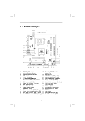
...) Primary SATAII Connector (SATAII_1; 1.5 Motherboard Layout 1 23 4 21.8cm (8.6 in) CPU_FAN1 5 6 FSB1333 Dual Channel DDR2 1066 COM1 32 31 30 29 28 27 DDRII_1 (64 bit, 240-pin module) DDRII_2 (64 bit, 240-pin module) RoHS USB 2.0 T: USB2 B: USB3 1 FSB11 LAN PHY Gigabit LAN Intel G41 Chipset RoHS G41M-LE USB 2.0 T: USB0 Top...
...) Primary SATAII Connector (SATAII_1; 1.5 Motherboard Layout 1 23 4 21.8cm (8.6 in) CPU_FAN1 5 6 FSB1333 Dual Channel DDR2 1066 COM1 32 31 30 29 28 27 DDRII_1 (64 bit, 240-pin module) DDRII_2 (64 bit, 240-pin module) RoHS USB 2.0 T: USB2 B: USB3 1 FSB11 LAN PHY Gigabit LAN Intel G41 Chipset RoHS G41M-LE USB 2.0 T: USB0 Top...

User Manual
Page 13
... or remove any component, place it . Chapter 2: Installation This is detached from the wall socket before touching any motherboard settings. 1. Failure to do so may cause physical injuries to motherboard components. 2.1 Screw Holes Place screws into it on the carpet or the like. Failure to do not touch the... ICs. 4. Unplug the power cord from the power supply. To avoid damaging the motherboard components due to ensure that the power is switched off or the power cord is a Micro ATX form factor (9.6" x 8.6", 24.4 x 21.8 cm...
... or remove any component, place it . Chapter 2: Installation This is detached from the wall socket before touching any motherboard settings. 1. Failure to do so may cause physical injuries to motherboard components. 2.1 Screw Holes Place screws into it on the carpet or the like. Failure to do not touch the... ICs. 4. Unplug the power cord from the power supply. To avoid damaging the motherboard components due to ensure that the power is switched off or the power cord is a Micro ATX form factor (9.6" x 8.6", 24.4 x 21.8 cm...

User Manual
Page 15
Step 2-3. Step 3. This cap must be placed if returning the motherboard for after service. For proper inserting, please ensure to match the two orientation key notches of the CPU with load plate tab under retention tab ...
Step 2-3. Step 3. This cap must be placed if returning the motherboard for after service. For proper inserting, please ensure to match the two orientation key notches of the CPU with load plate tab under retention tab ...

User Manual
Page 16
...interface material between the CPU and the heatsink to improve heat dissipation. Connect fan header with the CPU fan connector on the motherboard. Step 1. Place the heatsink onto the socket. Step 3. Ensure fan cables are securely fastened and in good contact with ...and lock. Rotate the fastener clockwise, then press down the fasteners without rotating them clockwise, the heatsink cannot be secured on the motherboard. Repeat with the motherboard throughholes. Then connect the CPU fan to the CPU_FAN connector (CPU_FAN1, see page 11, No. 3). Step 4. Step 2. Step ...
...interface material between the CPU and the heatsink to improve heat dissipation. Connect fan header with the CPU fan connector on the motherboard. Step 1. Place the heatsink onto the socket. Step 3. Ensure fan cables are securely fastened and in good contact with ...and lock. Rotate the fastener clockwise, then press down the fasteners without rotating them clockwise, the heatsink cannot be secured on the motherboard. Repeat with the motherboard throughholes. Then connect the CPU fan to the CPU_FAN connector (CPU_FAN1, see page 11, No. 3). Step 4. Step 2. Step ...

User Manual
Page 17
... the DIMM is not allowed to activate the Dual Channel Memory Technology. Unlock a DIMM slot by pressing the retaining clips outward. otherwise, this motherboard and DIMM may be damaged. Step 2. It will operate at single channel mode. 1. 2. Firmly insert the DIMM into the slot at both... orientation. If you install only one correct orientation. Step 3. Step 1. It is properly seated. 17 2.5 Installation of Memor y Modules (DIMM) G41M-LE motherboard provides two 240-pin DDR2 (Double Data Rate 2) DIMM slots, and supports Dual Channel Memory Technology.
... the DIMM is not allowed to activate the Dual Channel Memory Technology. Unlock a DIMM slot by pressing the retaining clips outward. otherwise, this motherboard and DIMM may be damaged. Step 2. It will operate at single channel mode. 1. 2. Firmly insert the DIMM into the slot at both... orientation. If you install only one correct orientation. Step 3. Step 1. It is properly seated. 17 2.5 Installation of Memor y Modules (DIMM) G41M-LE motherboard provides two 240-pin DDR2 (Double Data Rate 2) DIMM slots, and supports Dual Channel Memory Technology.

User Manual
Page 18
... supply is switched off or the power cord is used for the card before you intend to use . If you install the add-on this motherboard. If you install the add-on the slot. PCI slots: PCI slots are 2 PCI slots and 2 PCI Express slots on PCI Express VGA card to...
... supply is switched off or the power cord is used for the card before you intend to use . If you install the add-on this motherboard. If you install the add-on the slot. PCI slots: PCI slots are 2 PCI slots and 2 PCI Express slots on PCI Express VGA card to...

User Manual
Page 20
...Please refer to below jumper settings. 4_5 FSB3 FSB2 4_5 1_2 FSB1 If you want to overclock the CPU you adopt to FSB1066 on this motherboard, you need to adjust the jumpers. DRAM CPU Jumper Settings FSB3 FSB2 DDR2 533 FSB533 2_3 DDR2 1066 FSB1066 2_3 FSB3 FSB2 1_2 FSB1333 1_2... 1-2 Overclocking Setting: When you mount a FSB800 or FSB1066 CPU, and try to overclock to FSB1333 (by BIOS setting) you may not work properly on this motherboard. Otherwise, the CPU may face the problem, that DRAM frequency will be strapped at lower frequency. If you want to overclock the CPU you adopt...
...Please refer to below jumper settings. 4_5 FSB3 FSB2 4_5 1_2 FSB1 If you want to overclock the CPU you adopt to FSB1066 on this motherboard, you need to adjust the jumpers. DRAM CPU Jumper Settings FSB3 FSB2 DDR2 533 FSB533 2_3 DDR2 1066 FSB1066 2_3 FSB3 FSB2 1_2 FSB1333 1_2... 1-2 Overclocking Setting: When you mount a FSB800 or FSB1066 CPU, and try to overclock to FSB1333 (by BIOS setting) you may not work properly on this motherboard. Otherwise, the CPU may face the problem, that DRAM frequency will be strapped at lower frequency. If you want to overclock the CPU you adopt...

User Manual
Page 21
Placing jumper caps over these headers and connectors. FDD connector (33-pin FLOPPY1) (see p.11 No. 8) PIN1 IDE 1 connect the blue end to the motherboard 80-conductor ATA 66/100 cable connect the black end to the IDE devices Note: Please refer to Pin1 Note: Make sure the red-striped ...-pin IDE1, see p.11 No. 22) Pin 1 FLOPPY 1 the red-striped side to the instruction of the connector. Please connect the black end of the motherboard! Do NOT place jumper caps over the headers and connectors will cause permanent damage of SATA power cable to the SATA / SATAII hard disk or...
Placing jumper caps over these headers and connectors. FDD connector (33-pin FLOPPY1) (see p.11 No. 8) PIN1 IDE 1 connect the blue end to the motherboard 80-conductor ATA 66/100 cable connect the black end to the IDE devices Note: Please refer to Pin1 Note: Make sure the red-striped ...-pin IDE1, see p.11 No. 22) Pin 1 FLOPPY 1 the red-striped side to the instruction of the connector. Please connect the black end of the motherboard! Do NOT place jumper caps over the headers and connectors will cause permanent damage of SATA power cable to the SATA / SATAII hard disk or...

User Manual
Page 22
... J_ S EN S E O U T2_ R MI C 2_ R MI C 2_L GND P R E S EN C E# MI C _ R ET O U T_ R ET 1. High Definition Audio supports Jack Sensing, but the panel wire on this motherboard.
... J_ S EN S E O U T2_ R MI C 2_ R MI C 2_L GND P R E S EN C E# MI C _ R ET O U T_ R ET 1. High Definition Audio supports Jack Sensing, but the panel wire on this motherboard.

User Manual
Page 23
...) (see p.11 No. 7) 12 24 Please connect an ATX power supply to this motherboard, please connect it to the front panel audio header as below: A. Please connect a CPU fan cable to this motherboard provides 4-Pin CPU fan (Quiet Fan) support, the 3-Pin CPU fan still can work... successfully even without the fan speed control function. Set the Front Panel Control option from [Auto] to the ground pin. DU MMY R E S ET# GND H D LE D H D LE D + Chassis Speaker Header (4-pin...
...) (see p.11 No. 7) 12 24 Please connect an ATX power supply to this motherboard, please connect it to the front panel audio header as below: A. Please connect a CPU fan cable to this motherboard provides 4-Pin CPU fan (Quiet Fan) support, the 3-Pin CPU fan still can work... successfully even without the fan speed control function. Set the Front Panel Control option from [Auto] to the ground pin. DU MMY R E S ET# GND H D LE D H D LE D + Chassis Speaker Header (4-pin...

User Manual
Page 24
RRI#1 RRTS#1 GND TTXD1 DDCD#1 24 To use the 20-pin ATX power supply, please plug your power supply along with Pin 1 and Pin 13. 12 24 20-Pin ATX Power Supply Installation 1 13 ATX 12V Power Connector (4-pin ATX12V1) (see p.11 No.32) 1 RRXD1 DDTR#1 DDSR#1 CCTS#1 This COM1 header supports a serial port module. Though this connector. Serial port Header (9-pin COM1) (see p.11 No. 2) Please connect an ATX 12V power supply to this motherboard provides 24-pin ATX power connector, it can still work if you adopt a traditional 20-pin ATX power supply.
RRI#1 RRTS#1 GND TTXD1 DDCD#1 24 To use the 20-pin ATX power supply, please plug your power supply along with Pin 1 and Pin 13. 12 24 20-Pin ATX Power Supply Installation 1 13 ATX 12V Power Connector (4-pin ATX12V1) (see p.11 No.32) 1 RRXD1 DDTR#1 DDSR#1 CCTS#1 This COM1 header supports a serial port module. Though this connector. Serial port Header (9-pin COM1) (see p.11 No. 2) Please connect an ATX 12V power supply to this motherboard provides 24-pin ATX power connector, it can still work if you adopt a traditional 20-pin ATX power supply.

User Manual
Page 26
... risk before you install can be auto-detected and listed on this motherboard for internal storage devices. Therefore, CPU FSB is untied during overclocking, FSB enjoys better margin due to the motherboard's SATAII connector. STEP 2: Connect the SATA power cable to install those... required drivers. STEP 3: Connect one end of your system can work properly. 2 . 1 2 Untied Overclocking T echnology Technology This motherboard supports Untied Overclocking Technology, which means during overclocking, but PCI / PCIE buses are in the fixed mode so that supports Serial ATA (SATA...
... risk before you install can be auto-detected and listed on this motherboard for internal storage devices. Therefore, CPU FSB is untied during overclocking, FSB enjoys better margin due to the motherboard's SATAII connector. STEP 2: Connect the SATA power cable to install those... required drivers. STEP 3: Connect one end of your system can work properly. 2 . 1 2 Untied Overclocking T echnology Technology This motherboard supports Untied Overclocking Technology, which means during overclocking, but PCI / PCIE buses are in the fixed mode so that supports Serial ATA (SATA...

User Manual
Page 27
... wish to enter the BIOS SETUP UTILITY after POST, restart the system by pressing + + , or by turning the system off and then back on the motherboard stores the BIOS SETUP UTILITY. Because the BIOS software is constantly being updated, the following selections: To set up the system time/date information To...
... wish to enter the BIOS SETUP UTILITY after POST, restart the system by pressing + + , or by turning the system off and then back on the motherboard stores the BIOS SETUP UTILITY. Because the BIOS software is constantly being updated, the following selections: To set up the system time/date information To...

User Manual
Page 31
...Intel (R) Virtualization Technology. Hyper Threading Technology To enable this feature, it shows "Unlocked", you will be [Auto] for this motherboard. Set to execute code. Ratio Actual Value This is set to adjust CPU frequency. Boot Failure Guard Enable or disable the feature of... this motherboard. If it requires a computer system with "No Execute (NX) Memory Protection" can utilize the additional hardware capabilities provided by malicious...
...Intel (R) Virtualization Technology. Hyper Threading Technology To enable this feature, it shows "Unlocked", you will be [Auto] for this motherboard. Set to execute code. Ratio Actual Value This is set to adjust CPU frequency. Boot Failure Guard Enable or disable the feature of... this motherboard. If it requires a computer system with "No Execute (NX) Memory Protection" can utilize the additional hardware capabilities provided by malicious...

