
User Manual
Page 10
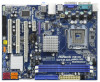
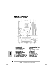
... 1 SPEAKER1 1 SATAII_1 20 19 18 17 16 15 14 13 12 SATAII_2 SATAII_4 6 7 8 9 10 11 1 PS2_USB_PWR1 Jumper 15 USB 2.0 Header (USB6_7, Blue) 2 775-Pin CPU Socket 16 USB 2.0 Header (USB4_5, Blue) 3 North Bridge Controller 17 System Panel Header (PANEL1, Orange) 4 CPU Fan Connector (CPU_FAN1) 18 BIOS SPI Chip 5 2 x 240-pin DDR3...
... 1 SPEAKER1 1 SATAII_1 20 19 18 17 16 15 14 13 12 SATAII_2 SATAII_4 6 7 8 9 10 11 1 PS2_USB_PWR1 Jumper 15 USB 2.0 Header (USB6_7, Blue) 2 775-Pin CPU Socket 16 USB 2.0 Header (USB4_5, Blue) 3 North Bridge Controller 17 System Panel Header (PANEL1, Orange) 4 CPU Fan Connector (CPU_FAN1) 18 BIOS SPI Chip 5 2 x 240-pin DDR3...
User Manual
Page 12
... component. 2. Make sure to the chassis. Failure to use a grounded wrist strap or touch a safety grounded object before installing or removing the motherboard. Chapter 2 Installation G41M-GS3 / G41M-S3 is detached from the wall socket before you install motherboard components or change any component, place it . Also remember to do not touch the ICs. 4.
... component. 2. Make sure to the chassis. Failure to use a grounded wrist strap or touch a safety grounded object before installing or removing the motherboard. Chapter 2 Installation G41M-GS3 / G41M-S3 is detached from the wall socket before you install motherboard components or change any component, place it . Also remember to do not touch the ICs. 4.
User Manual
Page 13
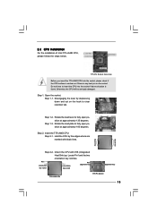
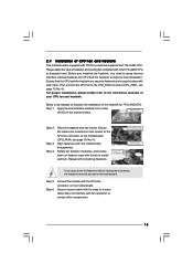
... 775-LAND CPU, please follow the steps below. 775-Pin Socket Overview Before you insert the 775-LAND CPU into the socket if above situation is any bent pin on the ShoockoetkMatrokedcCleoranerr retention tab. Open the socket: CPU Marked Corner Step 1-1. Rotate the load lever to fully...the 775-LAND CPU: Step 2-1. Step 1-3. Pin1 orientation key notch orientation key notch Pin1 alignment key alignment key 775-LAND CPU 775-Pin Socket 13 DLifitsLeevnergUapgtoin9g0° the lever by the edges where are marked with IHS (Integrated Heat Sink) up. Hold the CPU by depressing down ...
... 775-LAND CPU, please follow the steps below. 775-Pin Socket Overview Before you insert the 775-LAND CPU into the socket if above situation is any bent pin on the ShoockoetkMatrokedcCleoranerr retention tab. Open the socket: CPU Marked Corner Step 1-1. Rotate the load lever to fully...the 775-LAND CPU: Step 2-1. Step 1-3. Pin1 orientation key notch orientation key notch Pin1 alignment key alignment key 775-LAND CPU 775-Pin Socket 13 DLifitsLeevnergUapgtoin9g0° the lever by the edges where are marked with IHS (Integrated Heat Sink) up. Hold the CPU by depressing down ...
User Manual
Page 14
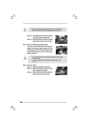
... cap to assist in removal. 1. Secure load lever with load plate tab under retention tab of the socket. Rotate the load plate onto the IHS. Step 4-2. Step 4-3. Step 2-3. It is within the socket and properly mated to the orient keys. Remove PnP Cap (Pick and Place Cap): Use your left...the load plate edge, engage PnP cap with right hand thumb and peel the cap from the socket while pressing on load plate, engage the load lever. Step 3. Step 4. Carefully place the CPU into the socket by using a purely vertical motion. Step 2-4. For proper inserting, please ensure to match the...
... cap to assist in removal. 1. Secure load lever with load plate tab under retention tab of the socket. Rotate the load plate onto the IHS. Step 4-2. Step 4-3. Step 2-3. It is within the socket and properly mated to the orient keys. Remove PnP Cap (Pick and Place Cap): Use your left...the load plate edge, engage PnP cap with right hand thumb and peel the cap from the socket while pressing on load plate, engage the load lever. Step 3. Step 4. Carefully place the CPU into the socket by using a purely vertical motion. Step 2-4. For proper inserting, please ensure to match the...
User Manual
Page 15
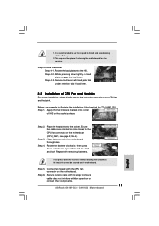
...to ensure cable does not interfere with thumb to the instruction manuals of your CPU fan and heatsink. Place the heatsink onto the socket. Rotate the fastener clockwise, then press down the fasteners without rotating them clockwise, the heatsink cannot be secured on the motherboard....CPU_FAN1, see page 10, No. 4). For proper installation, please kindly refer to install and lock. Connect fan header with 775-Pin socket that the CPU and the heatsink are oriented on side closest to illustrate the installation of heatsink and cooling fan compliant with remaining fasteners....
...to ensure cable does not interfere with thumb to the instruction manuals of your CPU fan and heatsink. Place the heatsink onto the socket. Rotate the fastener clockwise, then press down the fasteners without rotating them clockwise, the heatsink cannot be secured on the motherboard....CPU_FAN1, see page 10, No. 4). For proper installation, please kindly refer to install and lock. Connect fan header with 775-Pin socket that the CPU and the heatsink are oriented on side closest to illustrate the installation of heatsink and cooling fan compliant with remaining fasteners....
Quick Installation Guide
Page 2
Motherboard Layout English 1 PS2_USB_PWR1 Jumper 15 USB 2.0 Header (USB6_7, Blue) 2 775-Pin CPU Socket 16 USB 2.0 Header (USB4_5, Blue) 3 North Bridge Controller 17 System Panel Header (PANEL1, Orange) 4 CPU Fan Connector (CPU_FAN1) 18 ...FSB1 / FSB2 / FSB3 Jumper 13 Primary SATAII Connector (SATAII_1; Red) 27 ATX 12V Connector (ATX12V1) 14 Chassis Speaker Header (SPEAKER 1, Purple) 2 ASRock G41M-GS3 / G41M-S3 Motherboard Orange) 25 Print Port Header (LPT1, Purple) 12 Secondary SATAII Connector (SATAII_2; Blue) 20 Floppy Connector (FLOPPY1) 6 ATX Power Connector (ATXPWR1...
Motherboard Layout English 1 PS2_USB_PWR1 Jumper 15 USB 2.0 Header (USB6_7, Blue) 2 775-Pin CPU Socket 16 USB 2.0 Header (USB4_5, Blue) 3 North Bridge Controller 17 System Panel Header (PANEL1, Orange) 4 CPU Fan Connector (CPU_FAN1) 18 ...FSB1 / FSB2 / FSB3 Jumper 13 Primary SATAII Connector (SATAII_1; Red) 27 ATX 12V Connector (ATX12V1) 14 Chassis Speaker Header (SPEAKER 1, Purple) 2 ASRock G41M-GS3 / G41M-S3 Motherboard Orange) 25 Print Port Header (LPT1, Purple) 12 Secondary SATAII Connector (SATAII_2; Blue) 20 Floppy Connector (FLOPPY1) 6 ATX Power Connector (ATXPWR1...
Quick Installation Guide
Page 9
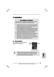
...may cause severe damage to static electricity, NEVER place your motherboard directly on the socket. Otherwise, the CPU will be seriously damaged. 9 ASRock G41M-GS3 / G41M-S3 Motherboard English 2. Failure to insert the CPU into the socket, please check if the CPU surface is unclean or if there is found....tighten the screws! Installation Pre-installation Precautions Take note of Intel 775-LAND CPU, please follow the steps below. 775-Pin Socket Overview Before you install motherboard components or change any component, place it on a grounded antstatic pad or in the bag that...
...may cause severe damage to static electricity, NEVER place your motherboard directly on the socket. Otherwise, the CPU will be seriously damaged. 9 ASRock G41M-GS3 / G41M-S3 Motherboard English 2. Failure to insert the CPU into the socket, please check if the CPU surface is unclean or if there is found....tighten the screws! Installation Pre-installation Precautions Take note of Intel 775-LAND CPU, please follow the steps below. 775-Pin Socket Overview Before you install motherboard components or change any component, place it on a grounded antstatic pad or in the bag that...
Quick Installation Guide
Page 10
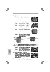
...by using a purely vertical motion. Pin1 orientation key notch orientation key notch Pin1 alignment key alignment key 775-LAND CPU 775-Pin Socket For proper inserting, please ensure to match the two orientation key notches of the CPU with the two alignment keys of PnP cap ...Step 2-4. Disengaging the lever by depressing down and out on center of the socket. Remove PnP Cap (Pick and Place Cap): Use your left hand index finger and thumb to assist in removal. 10 ASRock G41M-GS3 / G41M-S3 Motherboard Rotate the load plate to fully open position at approximately 135 ...
...by using a purely vertical motion. Pin1 orientation key notch orientation key notch Pin1 alignment key alignment key 775-LAND CPU 775-Pin Socket For proper inserting, please ensure to match the two orientation key notches of the CPU with the two alignment keys of PnP cap ...Step 2-4. Disengaging the lever by depressing down and out on center of the socket. Remove PnP Cap (Pick and Place Cap): Use your left hand index finger and thumb to assist in removal. 10 ASRock G41M-GS3 / G41M-S3 Motherboard Rotate the load plate to fully open position at approximately 135 ...
Quick Installation Guide
Page 11
.... Place the heatsink onto the socket. Step 1. While pressing down on load plate, engage the load lever. Rotate the fastener clockwise, then press down lightly on fastener caps with fan operation or contact other components. 11 ASRock G41M-GS3 / G41M-S3 Motherboard English Secure excess cable... with tie-wrap to ensure cable does not interfere with thumb to the CPU fan connector on the socket surface.
.... Place the heatsink onto the socket. Step 1. While pressing down on load plate, engage the load lever. Rotate the fastener clockwise, then press down lightly on fastener caps with fan operation or contact other components. 11 ASRock G41M-GS3 / G41M-S3 Motherboard English Secure excess cable... with tie-wrap to ensure cable does not interfere with thumb to the CPU fan connector on the socket surface.