
User Manual
Page 11
...(SPEAKER1, Purple) 13 Secondary SATAII Connector (SATAII_2; Red) 11 Fourth SATAII Connector (SATAII_4; 1.4 Motherboard Layout 1 23 4 PS2 Mouse PS2 Keyboard 1 PS2_USB_PWR1 ATX12V2 CPU_FAN1 56 COM1 G41C-GS DDRII_1 (64 bit, 240-piFnSmBod8ul0e)0 DDR3_A1 (64 bit, 240-FpinSBmo8d0ul0e) DDRII_2 (64 bit, 240...CMOS Battery 1 EUP_AUDIO1 AUDIO CODEC PCIE2 Super IO LPT1 CI1 CLRCMOS1 FLOPPY1 1 Intel G41 Chipset PCIE1 FSB1 1 PCI1 RoHS PCI2 8Mb BIOS PANEL 1 PLED PWRBTN 1 HDLED RESET Intel ICH7 IDE1 USB4_5 1 1 USB6_7 SATAII_1 SATAII_2 SPEAKER1 1 PWR_FAN1 CHA_FAN1 SATAII_3 SATAII_4...
...(SPEAKER1, Purple) 13 Secondary SATAII Connector (SATAII_2; Red) 11 Fourth SATAII Connector (SATAII_4; 1.4 Motherboard Layout 1 23 4 PS2 Mouse PS2 Keyboard 1 PS2_USB_PWR1 ATX12V2 CPU_FAN1 56 COM1 G41C-GS DDRII_1 (64 bit, 240-piFnSmBod8ul0e)0 DDR3_A1 (64 bit, 240-FpinSBmo8d0ul0e) DDRII_2 (64 bit, 240...CMOS Battery 1 EUP_AUDIO1 AUDIO CODEC PCIE2 Super IO LPT1 CI1 CLRCMOS1 FLOPPY1 1 Intel G41 Chipset PCIE1 FSB1 1 PCI1 RoHS PCI2 8Mb BIOS PANEL 1 PLED PWRBTN 1 HDLED RESET Intel ICH7 IDE1 USB4_5 1 1 USB6_7 SATAII_1 SATAII_2 SPEAKER1 1 PWR_FAN1 CHA_FAN1 SATAII_3 SATAII_4...

User Manual
Page 16
...the fastener clockwise, then press down the fasteners without rotating them clockwise, the heatsink cannot be secured on the motherboard (CPU_FAN1, see page 11, No. 3). Ensure that supports Intel 775-LAND CPU. Step 3. Step 6. Connect fan header with 775-Pin socket that the CPU and the ...heatsink are oriented on side closest to the CPU fan connector on the motherboard. Step 4. Please adopt the type of IHS on the motherboard. Step 5. Below is...
...the fastener clockwise, then press down the fasteners without rotating them clockwise, the heatsink cannot be secured on the motherboard (CPU_FAN1, see page 11, No. 3). Ensure that supports Intel 775-LAND CPU. Step 3. Step 6. Connect fan header with 775-Pin socket that the CPU and the ...heatsink are oriented on side closest to the CPU fan connector on the motherboard. Step 4. Please adopt the type of IHS on the motherboard. Step 5. Below is...

User Manual
Page 28
... as user defaults ? Select Screen Select Item Enter Go to page 8 for DDR2. DRAM Frequency If [Auto] is selected, the motherboard will detect the memory module(s) inserted and assigns appropriate frequency automatically. BIOS SETUP UTILITY Main OC Tweaker Advanced H/W Monitor Boot Security Exit ...OC Tweaker Settings DRAM Frequency DRAM Timing Configuration Ratio CMOS Setting 8 Intel (R) SpeedStep (tm) tech. Please refer to Sub Screen F1 General Help F9 Load Defaults F10 Save and Exit ESC Exit v02.54...
... as user defaults ? Select Screen Select Item Enter Go to page 8 for DDR2. DRAM Frequency If [Auto] is selected, the motherboard will detect the memory module(s) inserted and assigns appropriate frequency automatically. BIOS SETUP UTILITY Main OC Tweaker Advanced H/W Monitor Boot Security Exit ...OC Tweaker Settings DRAM Frequency DRAM Timing Configuration Ratio CMOS Setting 8 Intel (R) SpeedStep (tm) tech. Please refer to Sub Screen F1 General Help F9 Load Defaults F10 Save and Exit ESC Exit v02.54...

User Manual
Page 30
...want to enable this function, please set this to select VTT Voltage. Configuration options: [Auto], [Manual] and [Optimized]. The default value of this motherboard. Configuration options: [Auto], [0.67 x Vtt], [0.65 x Vtt], [0.63 x Vtt] and [0.615 x Vtt]. Ratio CMOS Setting If the ratio... status is unlocked, you will be hidden if the current CPU does not support Intel (R) SpeedStep(tm) tech.. Intel (R) SpeedStep(tm) tech. Configuration options for DDR3: [Auto], [1.30V] to enable this item appear to [2.41V]. Configuration options:...
...want to enable this function, please set this to select VTT Voltage. Configuration options: [Auto], [Manual] and [Optimized]. The default value of this motherboard. Configuration options: [Auto], [0.67 x Vtt], [0.65 x Vtt], [0.63 x Vtt] and [0.615 x Vtt]. Ratio CMOS Setting If the ratio... status is unlocked, you will be hidden if the current CPU does not support Intel (R) SpeedStep(tm) tech.. Intel (R) SpeedStep(tm) tech. Configuration options for DDR3: [Auto], [1.30V] to enable this item appear to [2.41V]. Configuration options:...

User Manual
Page 33
CPU Frequency (MHz) Use this to allow you changing the ratio value of this motherboard. Ratio CMOS Setting If the ratio status is [Auto]. This option will find this item appear to select Overclock Mode. On-Demand Clock Modulation [Auto]... (MHz) PCIE Frequency (MHz) Boot Failure Guard Spread Spectrum Ratio CMOS Setting 8 Enhanced Halt State Intel (R) Virtualization tech. The C1 state is set to adjust CPU frequency. CPU Thermal Throttling No-Execute Memory Protection Intel (R) SpeedStep (tm) tech. Boot Failure Guard Enable or disable the feature of the system caches. ...
CPU Frequency (MHz) Use this to allow you changing the ratio value of this motherboard. Ratio CMOS Setting If the ratio status is [Auto]. This option will find this item appear to select Overclock Mode. On-Demand Clock Modulation [Auto]... (MHz) PCIE Frequency (MHz) Boot Failure Guard Spread Spectrum Ratio CMOS Setting 8 Enhanced Halt State Intel (R) Virtualization tech. The C1 state is set to adjust CPU frequency. CPU Thermal Throttling No-Execute Memory Protection Intel (R) SpeedStep (tm) tech. Boot Failure Guard Enable or disable the feature of the system caches. ...

User Manual
Page 39
... the BIOS option, you can also choose our Intelligent Energy Saver utility to support increased content protection and robustness requirements for the motherboard through efficient memory utilization. PAVP is hardware-based 128-bit AES decryption. The default value is [Disabled]. The option [Maximum ... value is [DVMT Mode]. The default value is [Enabled]. DVMT Mode Select Use this option to adjust the shared memory size in Intel® 4 Series Express chipset family to enable this function. DVMT/FIXED Memory You are allowed to adjust DVMT mode. Primary Graphics Adapter...
... the BIOS option, you can also choose our Intelligent Energy Saver utility to support increased content protection and robustness requirements for the motherboard through efficient memory utilization. PAVP is hardware-based 128-bit AES decryption. The default value is [Disabled]. The option [Maximum ... value is [DVMT Mode]. The default value is [Enabled]. DVMT Mode Select Use this option to adjust the shared memory size in Intel® 4 Series Express chipset family to enable this function. DVMT/FIXED Memory You are allowed to adjust DVMT mode. Primary Graphics Adapter...

User Manual
Page 41
...this item to enable or disable ACPI HPET Table. ATA/IDE Configuration Please select [Compatible] when you plan to use this motherboard to submit Windows® VistaTM certification. 3.4.4 Storage Configuration BIOS SETUP UTILITY Advanced Storage Configuration ATA/IDE Configuration SATAII_1 SATAII_2 SATAII_3 SATAII_4...MS-DOS, Win NT) device is [Disabled]. If it is set to [SATA 1, SATA 3, IDE 1], then SATAII_2, SATAII_4 will not work . Because Intel® ICH7 south bridge only supports four IDE devices under legacy OS (Windows NT), you to select between [SATA 1, SATA 2, SATA 3, SATA 4], ...
...this item to enable or disable ACPI HPET Table. ATA/IDE Configuration Please select [Compatible] when you plan to use this motherboard to submit Windows® VistaTM certification. 3.4.4 Storage Configuration BIOS SETUP UTILITY Advanced Storage Configuration ATA/IDE Configuration SATAII_1 SATAII_2 SATAII_3 SATAII_4...MS-DOS, Win NT) device is [Disabled]. If it is set to [SATA 1, SATA 3, IDE 1], then SATAII_2, SATAII_4 will not work . Because Intel® ICH7 south bridge only supports four IDE devices under legacy OS (Windows NT), you to select between [SATA 1, SATA 2, SATA 3, SATA 4], ...

Quick Installation Guide
Page 2
...21 Chassis Intrusion Header (CI1) 22 FSB1 Jumper 23 EUP Audio Jumper (EUP_AUDIO1) 24 Front Panel Audio Header (HD_AUDIO1, Lime) 2 ASRock G41C-GS R2.0 Motherboard English Red) 14 Primary SATAII Connector (SATAII_1; Blue) 7 Power Fan Connector (PWR_FAN1) 8 Chassis Fan Connector (CHA_FAN1) 9 IDE1 ... Top: RJ-45 HD_AUDIO1 1 LAN CMOS Battery 1 EUP_AUDIO1 AUDIO CODEC PCIE2 Super IO LPT1 CI1 CLRCMOS1 FLOPPY1 1 Intel G41 Chipset PCIE1 FSB1 1 PCI1 RoHS Intel ICH7 IDE1 PWR_FAN1 CHA_FAN1 PCI2 8Mb BIOS PANEL 1 PLED PWRBTN 1 HDLED RESET USB4_5 1 1 USB6_7 SATAII_1 SATAII_3 SATAII_2...
...21 Chassis Intrusion Header (CI1) 22 FSB1 Jumper 23 EUP Audio Jumper (EUP_AUDIO1) 24 Front Panel Audio Header (HD_AUDIO1, Lime) 2 ASRock G41C-GS R2.0 Motherboard English Red) 14 Primary SATAII Connector (SATAII_1; Blue) 7 Power Fan Connector (PWR_FAN1) 8 Chassis Fan Connector (CHA_FAN1) 9 IDE1 ... Top: RJ-45 HD_AUDIO1 1 LAN CMOS Battery 1 EUP_AUDIO1 AUDIO CODEC PCIE2 Super IO LPT1 CI1 CLRCMOS1 FLOPPY1 1 Intel G41 Chipset PCIE1 FSB1 1 PCI1 RoHS Intel ICH7 IDE1 PWR_FAN1 CHA_FAN1 PCI2 8Mb BIOS PANEL 1 PLED PWRBTN 1 HDLED RESET USB4_5 1 1 USB6_7 SATAII_1 SATAII_3 SATAII_2...
Quick Installation Guide
Page 5
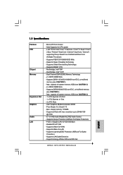
...-buffered memory (see CAUTION 1) - shared memory 1759MB - Supports D-Sub with max. Supports Energy Efficient Ethernet 802.3az 5 ASRock G41C-GS R2.0 Motherboard English Intel® Graphics Media Accelerator X4500 - PCIE x1 Gigabit LAN 10/100/1000 Mb/s - Max. Dual Channel DDR3/DDR2 Memory ... x DDR3 DIMM Slots - Max. Supports Lightning/ESD Protection (ASRock Full Spike Protection) - Supports Hyper-Threading Technology - Supports DDR3 1333(OC)/1066/800 non-ECC, un-buffered memory (see CAUTION 1) - Southbridge: Intel® ICH7 - Realtek RTL8111GR - Max. Supports Wake-On...
...-buffered memory (see CAUTION 1) - shared memory 1759MB - Supports D-Sub with max. Supports Energy Efficient Ethernet 802.3az 5 ASRock G41C-GS R2.0 Motherboard English Intel® Graphics Media Accelerator X4500 - PCIE x1 Gigabit LAN 10/100/1000 Mb/s - Max. Dual Channel DDR3/DDR2 Memory ... x DDR3 DIMM Slots - Max. Supports Lightning/ESD Protection (ASRock Full Spike Protection) - Supports Hyper-Threading Technology - Supports DDR3 1333(OC)/1066/800 non-ECC, un-buffered memory (see CAUTION 1) - Southbridge: Intel® ICH7 - Realtek RTL8111GR - Max. Supports Wake-On...


