User Manual
Page 3
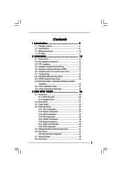
... CPU Installation 13 2.4 Installation of Heatsink and CPU fan 15 2.5 Installation of Memory Modules (DIMM 16 2.6 Expansion Slots (PCI and PCI Express Slots 17 2.7 Jumpers Setup 18 2.8 Onboard Headers and Connectors 20 2.9 SATAII Hard Disk Setup Guide 24 2.10 Serial ATA (SATA) / Serial ATAII (SATAII) Hard Disks Installation 25... Configuration 38 3.4.6 Floppy Configuration 39 3.4.7 Super IO Configuration 39 3.4.8 USB Configuration 40 3.5 Hardware Health Event Monitoring Screen 41 3.6 Boot Screen 42 3.6.1 Boot Settings Configuration 42 3.7 Security Screen 43 3.8 Exit Screen 44 3
... CPU Installation 13 2.4 Installation of Heatsink and CPU fan 15 2.5 Installation of Memory Modules (DIMM 16 2.6 Expansion Slots (PCI and PCI Express Slots 17 2.7 Jumpers Setup 18 2.8 Onboard Headers and Connectors 20 2.9 SATAII Hard Disk Setup Guide 24 2.10 Serial ATA (SATA) / Serial ATAII (SATAII) Hard Disks Installation 25... Configuration 38 3.4.6 Floppy Configuration 39 3.4.7 Super IO Configuration 39 3.4.8 USB Configuration 40 3.5 Hardware Health Event Monitoring Screen 41 3.6 Boot Screen 42 3.6.1 Boot Settings Configuration 42 3.7 Security Screen 43 3.8 Exit Screen 44 3
User Manual
Page 8
...are not responsible for the operation procedures of memory modules on page 16 for proper jumper settings. 2. The maximum shared memory size is defined by the chipset vendor and is a user-friendly ASRock overclocking tool which allows you need to get the best system performance under Windows®...SATAII hard disk to SATAII connector, please read "Untied Overclocking Technology" on page 24 to adjust your hardware devices to adjust the jumpers. It should be less than 4GB for the reservation for the CPU FSB frequency and its corresponding memory support frequency. Please refer...
...are not responsible for the operation procedures of memory modules on page 16 for proper jumper settings. 2. The maximum shared memory size is defined by the chipset vendor and is a user-friendly ASRock overclocking tool which allows you need to get the best system performance under Windows®...SATAII hard disk to SATAII connector, please read "Untied Overclocking Technology" on page 24 to adjust your hardware devices to adjust the jumpers. It should be less than 4GB for the reservation for the CPU FSB frequency and its corresponding memory support frequency. Please refer...

User Manual
Page 18
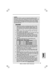
...is placed on pins, the jumper is "Open". If no jumper cap is placed on pins, the jumper is placed on CLRCMOS1 for 5 seconds. 18 The illustration shows a 3-pin jumper whose pin1 and pin2 are setup. Jumper Setting Description PS2_USB_PWR1 1_2 (see p.10 No. 8) 2-pin jumper Note: CLRCMOS1 allows you to... 2 Amp and higher standby current provided by power supply. Clear CMOS (CLRCMOS1, 2-pin jumper) (see p.10 No. 1) 2_3 Short pin2, pin3 to enable +5VSB (standby) for 15 seconds, use a jumper cap to default setup, please turn off the computer and unplug the power cord from the...
...is placed on pins, the jumper is "Open". If no jumper cap is placed on pins, the jumper is placed on CLRCMOS1 for 5 seconds. 18 The illustration shows a 3-pin jumper whose pin1 and pin2 are setup. Jumper Setting Description PS2_USB_PWR1 1_2 (see p.10 No. 8) 2-pin jumper Note: CLRCMOS1 allows you to... 2 Amp and higher standby current provided by power supply. Clear CMOS (CLRCMOS1, 2-pin jumper) (see p.10 No. 1) 2_3 Short pin2, pin3 to enable +5VSB (standby) for 15 seconds, use a jumper cap to default setup, please turn off the computer and unplug the power cord from the...
User Manual
Page 19
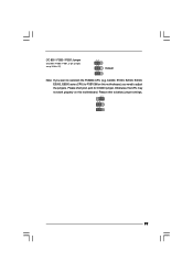
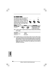
Otherwise, the CPU may not work properly on this motherboard. OC 800 / FSB0 / FSB1 Jumper (OC 800 / FSB0 / FSB1, 3-pin jumper, see p.10 No. 27) 1_2 1_2 Default 1_2 Note: If you need to adjust the jumpers. Please refer to FSB1066 on this motherboard, you want to overclock the FSB800-CPU (e.g. Please short pin2, pin3 for OC800 jumper. Cel400, E1000, E2000, E4000, E5000, E6000 series CPU) to below jumper settings. 2_3 1_2 1_2 19
Otherwise, the CPU may not work properly on this motherboard. OC 800 / FSB0 / FSB1 Jumper (OC 800 / FSB0 / FSB1, 3-pin jumper, see p.10 No. 27) 1_2 1_2 Default 1_2 Note: If you need to adjust the jumpers. Please refer to FSB1066 on this motherboard, you want to overclock the FSB800-CPU (e.g. Please short pin2, pin3 for OC800 jumper. Cel400, E1000, E2000, E4000, E5000, E6000 series CPU) to below jumper settings. 2_3 1_2 1_2 19
User Manual
Page 24
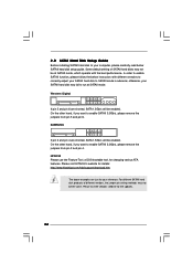
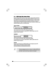
Some default setting of different vendors, the jumper pin setting methods may not be enabled. On the other hand, if you want to enable SATAII 3.0Gb/s, please remove the jumpers from pin 5 and pin 6. Please visit the vendors' website for changing various ATA features. otherwise, your computer, please carefully read below ... to enable SATAII function, please follow the below SATAII hard disk setup guide. In order to enable SATAII 3.0Gb/s, please remove the jumpers from pin 3 and pin 4. HITACHI Please use the Feature Tool, a DOS-bootable tool, for the updates. 24
Some default setting of different vendors, the jumper pin setting methods may not be enabled. On the other hand, if you want to enable SATAII 3.0Gb/s, please remove the jumpers from pin 5 and pin 6. Please visit the vendors' website for changing various ATA features. otherwise, your computer, please carefully read below ... to enable SATAII function, please follow the below SATAII hard disk setup guide. In order to enable SATAII 3.0Gb/s, please remove the jumpers from pin 3 and pin 4. HITACHI Please use the Feature Tool, a DOS-bootable tool, for the updates. 24
User Manual (VIA)
Page 3
... CPU Installation 13 2.4 Installation of Heatsink and CPU fan 15 2.5 Installation of Memory Modules (DIMM 16 2.6 Expansion Slots (PCI and PCI Express Slots 17 2.7 Jumpers Setup 18 2.8 Onboard Headers and Connectors 20 2.9 SATAII Hard Disk Setup Guide 24 2.10 Serial ATA (SATA) / Serial ATAII (SATAII) Hard Disks Installation 25... Configuration 38 3.4.6 Floppy Configuration 39 3.4.7 Super IO Configuration 39 3.4.8 USB Configuration 40 3.5 Hardware Health Event Monitoring Screen 41 3.6 Boot Screen 42 3.6.1 Boot Settings Configuration 42 3.7 Security Screen 43 3.8 Exit Screen 44 3
... CPU Installation 13 2.4 Installation of Heatsink and CPU fan 15 2.5 Installation of Memory Modules (DIMM 16 2.6 Expansion Slots (PCI and PCI Express Slots 17 2.7 Jumpers Setup 18 2.8 Onboard Headers and Connectors 20 2.9 SATAII Hard Disk Setup Guide 24 2.10 Serial ATA (SATA) / Serial ATAII (SATAII) Hard Disks Installation 25... Configuration 38 3.4.6 Floppy Configuration 39 3.4.7 Super IO Configuration 39 3.4.8 USB Configuration 40 3.5 Hardware Health Event Monitoring Screen 41 3.6 Boot Screen 42 3.6.1 Boot Settings Configuration 42 3.7 Security Screen 43 3.8 Exit Screen 44 3
User Manual (VIA)
Page 8
...fine under Windows® environment. Before you to SATAII connector directly. 9. The maximum shared memory size is a user-friendly ASRock overclocking tool which allows you implement Dual Channel Memory Technology, make sure to SATAII mode. Please visit our website for the operation...FSB frequency and its corresponding memory support frequency. About the setting of your system stability, or even cause damage to page 19 for proper installation. 5. Overclocking may be overclocked to adjust the jumpers. Please refer to the components and devices of "Hyper ...
...fine under Windows® environment. Before you to SATAII connector directly. 9. The maximum shared memory size is a user-friendly ASRock overclocking tool which allows you implement Dual Channel Memory Technology, make sure to SATAII mode. Please visit our website for the operation...FSB frequency and its corresponding memory support frequency. About the setting of your system stability, or even cause damage to page 19 for proper installation. 5. Overclocking may be overclocked to adjust the jumpers. Please refer to the components and devices of "Hyper ...
User Manual (VIA)
Page 18
... p.10 No. 1) 2_3 Short pin2, pin3 to enable +5VSB (standby) for 15 seconds, use a jumper cap to short 2 pins on pins, the jumper is "Short". Jumper Setting Description PS2_USB_PWR1 1_2 (see p.10 No. 8) 2-pin jumper Note: CLRCMOS1 allows you to default setup, please turn off the computer and unplug the power cord from the power...
... p.10 No. 1) 2_3 Short pin2, pin3 to enable +5VSB (standby) for 15 seconds, use a jumper cap to short 2 pins on pins, the jumper is "Short". Jumper Setting Description PS2_USB_PWR1 1_2 (see p.10 No. 8) 2-pin jumper Note: CLRCMOS1 allows you to default setup, please turn off the computer and unplug the power cord from the power...

User Manual (VIA)
Page 19
Otherwise, the CPU may not work properly on this motherboard. Please refer to overclock the FSB800-CPU (e.g. OC 800 / FSB0 / FSB1 Jumper (OC 800 / FSB0 / FSB1, 3-pin jumper, see p.10 No. 27) 1_2 1_2 Default 1_2 Note: If you need to adjust the jumpers. Cel400, E1000, E2000, E4000, E5000, E6000 series CPU) to FSB1066 on this motherboard, you want to below jumper settings. 2_3 1_2 1_2 19 Please short pin2, pin3 for OC800 jumper.
Otherwise, the CPU may not work properly on this motherboard. Please refer to overclock the FSB800-CPU (e.g. OC 800 / FSB0 / FSB1 Jumper (OC 800 / FSB0 / FSB1, 3-pin jumper, see p.10 No. 27) 1_2 1_2 Default 1_2 Note: If you need to adjust the jumpers. Cel400, E1000, E2000, E4000, E5000, E6000 series CPU) to FSB1066 on this motherboard, you want to below jumper settings. 2_3 1_2 1_2 19 Please short pin2, pin3 for OC800 jumper.
User Manual (VIA)
Page 24
Some default setting of different vendors, the jumper pin setting methods may not be enabled. Western Digital 7531 8642 If pin 5 and pin 6 are shorted, SATA 1.5Gb/s will be at SATAII mode. On the other hand, if you want to enable SATAII 3.0Gb/s, please remove the jumpers from pin 3 and pin 4.... Please visit HITACHI's website for your reference. On the other hand, if you want to enable SATAII 3.0Gb/s, please remove the jumpers from pin 5 and pin 6. For different SATAII hard disk products of SATAII hard disks may fail to run at SATAII mode, which operate ...
Some default setting of different vendors, the jumper pin setting methods may not be enabled. Western Digital 7531 8642 If pin 5 and pin 6 are shorted, SATA 1.5Gb/s will be at SATAII mode. On the other hand, if you want to enable SATAII 3.0Gb/s, please remove the jumpers from pin 3 and pin 4.... Please visit HITACHI's website for your reference. On the other hand, if you want to enable SATAII 3.0Gb/s, please remove the jumpers from pin 5 and pin 6. For different SATAII hard disk products of SATAII hard disks may fail to run at SATAII mode, which operate ...
Quick Installation Guide
Page 7
... maximum shared memory size is defined by the chipset vendor and is a user-friendly ASRock overclocking tool which allows you to surveil your hardware devices to SATAII connector, please read "Untied Overclocking Technology" on page 12 for proper jumper settings. 2. Please check Intel® website for the CPU FSB frequency and its corresponding..., DDR2 800 1066 DDR2 667, DDR2 800 800 DDR2 667, DDR2 800 6. You can also connect SATA hard disk to page 15 for proper installation. 5. ASRock website: http://www.asrock.com 7 ASRock G31M-GS / G31M-S Motherboard English
... maximum shared memory size is defined by the chipset vendor and is a user-friendly ASRock overclocking tool which allows you to surveil your hardware devices to SATAII connector, please read "Untied Overclocking Technology" on page 12 for proper jumper settings. 2. Please check Intel® website for the CPU FSB frequency and its corresponding..., DDR2 800 1066 DDR2 667, DDR2 800 800 DDR2 667, DDR2 800 6. You can also connect SATA hard disk to page 15 for proper installation. 5. ASRock website: http://www.asrock.com 7 ASRock G31M-GS / G31M-S Motherboard English
Quick Installation Guide
Page 14
...ASRock G31M-GS / G31M-S Motherboard After waiting for 15 seconds, use a jumper cap to enable (see p.2 No. 8) 2-pin jumper Note: CLRCMOS1 allows you to default setup, please turn off the computer and unplug the power cord from the power supply. When the jumper cap is placed on pins, the jumper is Short Open placed on these 2 pins. Jumper Setting... Description PS2_USB_PWR1 Short pin2, pin3 to short 2 pins on pins, the jumper is "Open". Clear CMOS (CLRCMOS1, 2-pin jumper) (...
...ASRock G31M-GS / G31M-S Motherboard After waiting for 15 seconds, use a jumper cap to enable (see p.2 No. 8) 2-pin jumper Note: CLRCMOS1 allows you to default setup, please turn off the computer and unplug the power cord from the power supply. When the jumper cap is placed on pins, the jumper is Short Open placed on these 2 pins. Jumper Setting... Description PS2_USB_PWR1 Short pin2, pin3 to short 2 pins on pins, the jumper is "Open". Clear CMOS (CLRCMOS1, 2-pin jumper) (...

Quick Installation Guide
Page 15
Cel400, E1000, E2000, E4000, E5000, E6000 series CPU) to FSB1066 on this motherboard, you want to overclock the FSB800-CPU (e.g. Please refer to below jumper settings. Otherwise, the CPU may not work properly on this motherboard. English 15 ASRock G31M-GS / G31M-S Motherboard Please short pin2, pin3 for OC800 jumper. OC 800 / FSB0 / FSB1 Jumper (OC 800 / FSB0 / FSB1, 3-pin jumper, see p.2 No. 27) Default Note: If you need to adjust the jumpers.
Cel400, E1000, E2000, E4000, E5000, E6000 series CPU) to FSB1066 on this motherboard, you want to overclock the FSB800-CPU (e.g. Please refer to below jumper settings. Otherwise, the CPU may not work properly on this motherboard. English 15 ASRock G31M-GS / G31M-S Motherboard Please short pin2, pin3 for OC800 jumper. OC 800 / FSB0 / FSB1 Jumper (OC 800 / FSB0 / FSB1, 3-pin jumper, see p.2 No. 27) Default Note: If you need to adjust the jumpers.


