
User Manual
Page 2
... purpose, without intent to change without notice, and should not be constructed as a commitment by ASRock. CALIFORNIA, USA ONLY The Lithium battery adopted on this motherboard contains Perchlorate, a toxic substance controlled in this manual are used only for informational use only and... subject to infringe. ASRock assumes no event shall ASRock, its directors, officers, employees, or agents be liable for any indirect...
... purpose, without intent to change without notice, and should not be constructed as a commitment by ASRock. CALIFORNIA, USA ONLY The Lithium battery adopted on this motherboard contains Perchlorate, a toxic substance controlled in this manual are used only for informational use only and... subject to infringe. ASRock assumes no event shall ASRock, its directors, officers, employees, or agents be liable for any indirect...

User Manual
Page 3
Introduction 5 1.1 Package Contents 5 1.2 Specifications 6 1.3 Unique Features 10 1.4 Motherboard Layout 14 1.5 I/O Panel 15 2. Contents 1. Installation 17 Pre-installation Precautions 17 2.1 CPU Installation 18 2.2 Installation of CPU Fan and Heatsink 18 ...21 2.5 CrossFireXTM, 3-Way CrossFireXTM and Quad CrossFireXTM Operation Guide 22 2.6 Dual Graphics Operation Guide 27 2.7 Multi Monitor and Surround Display Features 29 2.8 ASRock Smart Remote Installation Guide 32 2.9 Jumpers Setup 34 2.10 Onboard Headers and Connectors 35 2.11 Smart Switches 40 2.12 Dr. Debug 41 2.13 ...
Introduction 5 1.1 Package Contents 5 1.2 Specifications 6 1.3 Unique Features 10 1.4 Motherboard Layout 14 1.5 I/O Panel 15 2. Contents 1. Installation 17 Pre-installation Precautions 17 2.1 CPU Installation 18 2.2 Installation of CPU Fan and Heatsink 18 ...21 2.5 CrossFireXTM, 3-Way CrossFireXTM and Quad CrossFireXTM Operation Guide 22 2.6 Dual Graphics Operation Guide 27 2.7 Multi Monitor and Surround Display Features 29 2.8 ASRock Smart Remote Installation Guide 32 2.9 Jumpers Setup 34 2.10 Onboard Headers and Connectors 35 2.11 Smart Switches 40 2.12 Dr. Debug 41 2.13 ...

User Manual
Page 5
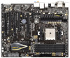
... version will be subject to change without further notice. www.asrock.com/support/index.asp 1.1 Package Contents ASRock FM2A85X Extreme6 Motherboard (ATX Form Factor) ASRock FM2A85X Extreme6 Quick Installation Guide ASRock FM2A85X Extreme6 Support CD 4 x Serial ATA (SATA) Data Cables (Optional) 1 x I/O Panel Shield ASRock Reminds You... In case any modifications of the motherboard and stepby-step guide to this manual, chapter 1 and 2 contain...
... version will be subject to change without further notice. www.asrock.com/support/index.asp 1.1 Package Contents ASRock FM2A85X Extreme6 Motherboard (ATX Form Factor) ASRock FM2A85X Extreme6 Quick Installation Guide ASRock FM2A85X Extreme6 Support CD 4 x Serial ATA (SATA) Data Cables (Optional) 1 x I/O Panel Shield ASRock Reminds You... In case any modifications of the motherboard and stepby-step guide to this manual, chapter 1 and 2 contain...
User Manual
Page 9
... the reservation for possible damage caused by overclocking. We are only supported under Windows® 8 64-bit / 8 / 7 64-bit / 7. ASRock website http://www.asrock.com 2. For Windows® 64-bit OS with overclocking, including adjusting the setting in EDID. You can choose to the components and devices of...Please realize that Windows® cannot use ASRock XFast RAM to -HDMI adapter, the DVID port can use . 3. Due to the memory support list on the CPU you want to adopt DDR3 2600/2400/2133/1866/1600 memory module on this motherboard, please refer to the operating system limitation...
... the reservation for possible damage caused by overclocking. We are only supported under Windows® 8 64-bit / 8 / 7 64-bit / 7. ASRock website http://www.asrock.com 2. For Windows® 64-bit OS with overclocking, including adjusting the setting in EDID. You can choose to the components and devices of...Please realize that Windows® cannot use ASRock XFast RAM to -HDMI adapter, the DVID port can use . 3. Due to the memory support list on the CPU you want to adopt DDR3 2600/2400/2133/1866/1600 memory module on this motherboard, please refer to the operating system limitation...

User Manual
Page 12
... S4/S5 state. After copying the RAID driver to your USB storage device. Only USB2.0 ports support this function. ASRock Internet Flash ASRock Internet Flash searches for available UEFI firmware updates from our servers and flash them without permission to modify the system time .... In other users. ASRock UEFI System Browser ASRock UEFI system browser is a useful tool included in UEFI setup. ASRock Easy RAID Installer ASRock Easy RAID Installer can help you can easily examine the current system configuration in graphical UEFI. You may prevent motherboard damages due to dampness by...
... S4/S5 state. After copying the RAID driver to your USB storage device. Only USB2.0 ports support this function. ASRock Internet Flash ASRock Internet Flash searches for available UEFI firmware updates from our servers and flash them without permission to modify the system time .... In other users. ASRock UEFI System Browser ASRock UEFI system browser is a useful tool included in UEFI setup. ASRock Easy RAID Installer ASRock Easy RAID Installer can help you can easily examine the current system configuration in graphical UEFI. You may prevent motherboard damages due to dampness by...
User Manual
Page 14
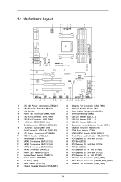
1.4 Motherboard Layout USB 3.0 Ps2 T: USB1 Keyboard B: USB2 /Mouse 1 ATX12V1 23 4 56 PWR_FAN1 CPU_FAN1 CPU_FAN2 7 8 DDR3 2600+ VGA1 DVI1 DDR3_B2 (64 bit, 240-pin module) DDR3_A2 (64 ...: CROSS_FIRE_PWR1 CHA_FAN3 XFast RAM ATXPWR1 9 10 USB3_5_6 CTR BASS LINE IN REAR SPK FRONT XFast LAN Top: Center: Bottom: MIC IN 41 CHA_FAN2 40 PCIE1 FM2A85X Extreme6 Front USB 3.0 39 PCIE2 LAN DX11 CMOS Dual Graphics 38 PCIE3 BATTERY AMD A85X 11 37 Super PCI1 CLRCMOS1 (Hudson-D4) Chipset SATA3_1_2 I/O ErP/EuP...
1.4 Motherboard Layout USB 3.0 Ps2 T: USB1 Keyboard B: USB2 /Mouse 1 ATX12V1 23 4 56 PWR_FAN1 CPU_FAN1 CPU_FAN2 7 8 DDR3 2600+ VGA1 DVI1 DDR3_B2 (64 bit, 240-pin module) DDR3_A2 (64 ...: CROSS_FIRE_PWR1 CHA_FAN3 XFast RAM ATXPWR1 9 10 USB3_5_6 CTR BASS LINE IN REAR SPK FRONT XFast LAN Top: Center: Bottom: MIC IN 41 CHA_FAN2 40 PCIE1 FM2A85X Extreme6 Front USB 3.0 39 PCIE2 LAN DX11 CMOS Dual Graphics 38 PCIE3 BATTERY AMD A85X 11 37 Super PCI1 CLRCMOS1 (Hudson-D4) Chipset SATA3_1_2 I/O ErP/EuP...

User Manual
Page 17
... over-tighten the screws! Before you install or remove any component, place it . Whenever you install the motherboard, study the configuration of the following precautions before you install motherboard components or change any component. 2. Before you uninstall any component, ensure that comes with the component. 5.... 2. Hold components by the edges and do so may damage the motherboard. 17 Doing so may cause severe damage to do not touch the ICs. 4. When placing screws into it on the carpet or ...
... over-tighten the screws! Before you install or remove any component, place it . Whenever you install the motherboard, study the configuration of the following precautions before you install motherboard components or change any component. 2. Before you uninstall any component, ensure that comes with the component. 5.... 2. Hold components by the edges and do so may damage the motherboard. 17 Doing so may cause severe damage to do not touch the ICs. 4. When placing screws into it on the carpet or ...

User Manual
Page 18
... Down And Lock To The Socket Corner Small The Socket Lever Triangle 2.2 Installation of CPU Fan and Heatsink After you install the CPU into this motherboard, it is in place. Make sure that the CPU corner with the golden triangle matches the socket corner with each other. Then connect the CPU...
... Down And Lock To The Socket Corner Small The Socket Lever Triangle 2.2 Installation of CPU Fan and Heatsink After you install the CPU into this motherboard, it is in place. Make sure that the CPU corner with the golden triangle matches the socket corner with each other. Then connect the CPU...

User Manual
Page 19
...of memory modules is NOT installed in the same Dual Channel, for optimal compatibility and reliability, it is recommended to install them on this motherboard and DIMM may refer to install a DDR or DDR2 memory module into DDR3 slot; If you want to install two memory modules, for... example, installing a pair of Memory Modules (DIMM) This motherboard provides four 240-pin DDR3 (Double Data Rate 3) DIMM slots, and supports Dual Channel Memory Technology. 2.3 Installation of memory modules in DDR3_A1 and ...
...of memory modules is NOT installed in the same Dual Channel, for optimal compatibility and reliability, it is recommended to install them on this motherboard and DIMM may refer to install a DDR or DDR2 memory module into DDR3 slot; If you want to install two memory modules, for... example, installing a pair of Memory Modules (DIMM) This motherboard provides four 240-pin DDR3 (Double Data Rate 3) DIMM slots, and supports Dual Channel Memory Technology. 2.3 Installation of memory modules in DDR3_A1 and ...

User Manual
Page 20
... 2. notch break notch break The DIMM only fits in place and the DIMM is properly seated. 20 Step 1. Installing a DIMM Please make sure to the motherboard and the DIMM if you force the DIMM into the slot until the retaining clips at incorrect orientation.
... 2. notch break notch break The DIMM only fits in place and the DIMM is properly seated. 20 Step 1. Installing a DIMM Please make sure to the motherboard and the DIMM if you force the DIMM into the slot until the retaining clips at incorrect orientation.

User Manual
Page 21
... width cards, such as Gigabit LAN card and SATA2 card. Step 2. Fasten the card to install a PCI Express x16 graphics card on this motherboard. Step 4. PCIE2 / PCIE4 (PCIE x16 slot) is occupied, the DisplayPort cannot be used. Therefore, both these two slots will work at x4... bandwidth. 4. Please connect a chassis fan to motherboard chassis fan connector (CHA_FAN1, CHA_FAN2 or CHA_FAN3) when using multiple graphics cards for the card before you intend to use . When PCIE2 slot ...
... width cards, such as Gigabit LAN card and SATA2 card. Step 2. Fasten the card to install a PCI Express x16 graphics card on this motherboard. Step 4. PCIE2 / PCIE4 (PCIE x16 slot) is occupied, the DisplayPort cannot be used. Therefore, both these two slots will work at x4... bandwidth. 4. Please connect a chassis fan to motherboard chassis fan connector (CHA_FAN1, CHA_FAN2 or CHA_FAN3) when using multiple graphics cards for the card before you intend to use . When PCIE2 slot ...

User Manual
Page 22
...performance and image quality in a single PC. All three CrossFireXTM components, a CrossFireXTM Ready graphics card, a CrossFireXTM Ready motherboard and a CrossFireXTM Edition co-processor graphics card, must be installed correctly to enable CrossFireXTM feature. If a customer incorrectly ... in the future, please refer to PCIE4 slot. 2.5 CrossFireXTM, 3-Way CrossFireXTM and Quad CrossFireXTM Operation Guide This motherboard supports CrossFireXTM, 3-way CrossFireXTM and Quad CrossFireXTM feature. Step 1. For other Radeon graphics card to AMD graphics card manuals...
...performance and image quality in a single PC. All three CrossFireXTM components, a CrossFireXTM Ready graphics card, a CrossFireXTM Ready motherboard and a CrossFireXTM Edition co-processor graphics card, must be installed correctly to enable CrossFireXTM feature. If a customer incorrectly ... in the future, please refer to PCIE4 slot. 2.5 CrossFireXTM, 3-Way CrossFireXTM and Quad CrossFireXTM Operation Guide This motherboard supports CrossFireXTM, 3-way CrossFireXTM and Quad CrossFireXTM feature. Step 1. For other Radeon graphics card to AMD graphics card manuals...

User Manual
Page 23
... the Radeon graphics card on the top of Radeon graphics cards. (CrossFire Bridge is provided with the graphics card you purchase, not bundled with this motherboard. Step 2. Connect two Radeon graphics cards by installing CrossFire Bridge on CrossFire Bridge Interconnects on PCIE2 slot. (You may use the DVI to D-Sub adapter...
... the Radeon graphics card on the top of Radeon graphics cards. (CrossFire Bridge is provided with the graphics card you purchase, not bundled with this motherboard. Step 2. Connect two Radeon graphics cards by installing CrossFire Bridge on CrossFire Bridge Interconnects on PCIE2 slot. (You may use the DVI to D-Sub adapter...

User Manual
Page 24
... 1. Make sure that are properly seated on PCIE4 and PCIE5 slots. (CrossFireTM Bridge is provided with the graphics card you purchase, not bundled with this motherboard.
... 1. Make sure that are properly seated on PCIE4 and PCIE5 slots. (CrossFireTM Bridge is provided with the graphics card you purchase, not bundled with this motherboard.
User Manual
Page 27
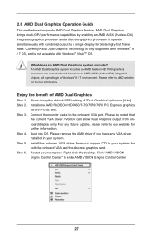
...Control Center" to AMD website for further information. An AMD Dual Graphics system includes an AMD Radeon HD 7000 graphics processor and a motherboard based on [Auto]. Step 4. Boot into OS. Please remove the AMD driver if you have any future update, please refer to ...operate simultaneously with Windows® VistaTM OS. Right-click the desktop. 2.6 AMD Dual Graphics Operation Guide This motherboard supports AMD Dual Graphics feature. Step 2. AMD Dual Graphics brings multi-GPU performance capabilities by enabling an AMD A85X (Hudson-D4) integrated...
...Control Center" to AMD website for further information. An AMD Dual Graphics system includes an AMD Radeon HD 7000 graphics processor and a motherboard based on [Auto]. Step 4. Boot into OS. Please remove the AMD driver if you have any future update, please refer to ...operate simultaneously with Windows® VistaTM OS. Right-click the desktop. 2.6 AMD Dual Graphics Operation Guide This motherboard supports AMD Dual Graphics feature. Step 2. AMD Dual Graphics brings multi-GPU performance capabilities by enabling an AMD A85X (Hudson-D4) integrated...

User Manual
Page 29
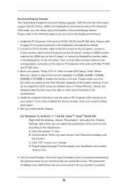
This motherboard also provides independent display controllers for DVI-D, D-Sub, HDMI and DisplayPort to the DVI port only. 4. Connect DVI-D monitor cable to DVI-D port on the I/O ... the benefits of them. 2. When PCIE2 slot is occupied, the DisplayPort cannot be used. 29 2.7 Multi Monitor and Surround Display Features Multi Monitor Feature This motherboard supports multi monitor feature. With the internal VGA output support (DVI-D, D-Sub, HDMI and DisplayPort), you playback HDCP-protected video from our support CD to...
This motherboard also provides independent display controllers for DVI-D, D-Sub, HDMI and DisplayPort to the DVI port only. 4. Connect DVI-D monitor cable to DVI-D port on the I/O ... the benefits of them. 2. When PCIE2 slot is occupied, the DisplayPort cannot be used. 29 2.7 Multi Monitor and Surround Display Features Multi Monitor Feature This motherboard supports multi monitor feature. With the internal VGA output support (DVI-D, D-Sub, HDMI and DisplayPort), you playback HDCP-protected video from our support CD to...
User Manual
Page 30
...3. Set up a surround display environment: 1. A. D. The placement of the multi-monitor according to nine. 6. Surround Display Feature This motherboard supports surround display upgrade. Please refer to page 21 for proper expansion card installation procedures for the display icon identified by the number three ...Install the onboard VGA driver and the add-on PCI Express VGA cards, you select is my main monitor" and "Extend the desktop onto this motherboard. 4. Enter "Share Memory" option to adjust the memory capability to [32MB], [64MB], [128MB], [256MB] or [512MB] to this monitor...
...3. Set up a surround display environment: 1. A. D. The placement of the multi-monitor according to nine. 6. Surround Display Feature This motherboard supports surround display upgrade. Please refer to page 21 for proper expansion card installation procedures for the display icon identified by the number three ...Install the onboard VGA driver and the add-on PCI Express VGA cards, you select is my main monitor" and "Extend the desktop onto this motherboard. 4. Enter "Share Memory" option to adjust the memory capability to [32MB], [64MB], [128MB], [256MB] or [512MB] to this monitor...

User Manual
Page 31
... content as it is highly recommended that the HDTV or LCD monitor you purchase is compatible. 31 HDCP Function HDCP function is supported on this motherboard, you need to adopt the monitor that supports HDCP function as well. such as a computer, DVD player or set -top-boxes, as well as a monitor...
... content as it is highly recommended that the HDTV or LCD monitor you purchase is compatible. 31 HDCP Function HDCP function is supported on this motherboard, you need to adopt the monitor that supports HDCP function as well. such as a computer, DVD player or set -top-boxes, as well as a monitor...
User Manual
Page 32
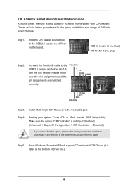
Press or to the USB 2.0 header on ASRock motherboard. Step5. Step1. Find the CIR header located next to enter BIOS Setup Utility. USB 2.0 header ... header. Step4. Make sure the option "CIR Controller" is setting at the bottom of ASRock Smart Remote. Enter Windows. 2.8 ASRock Smart Remote Installation Guide ASRock Smart Remote is only used for the quick installation and usage of driver list.) 32 Execute... Multi-Angle CIR Receiver to the USB 2.0 header (as below procedures for ASRock motherboard with CIR header. Please refer to the front USB port.
Press or to the USB 2.0 header on ASRock motherboard. Step5. Step1. Find the CIR header located next to enter BIOS Setup Utility. USB 2.0 header ... header. Step4. Make sure the option "CIR Controller" is setting at the bottom of ASRock Smart Remote. Enter Windows. 2.8 ASRock Smart Remote Installation Guide ASRock Smart Remote is only used for the quick installation and usage of driver list.) 32 Execute... Multi-Angle CIR Receiver to the USB 2.0 header (as below procedures for ASRock motherboard with CIR header. Please refer to the front USB port.

User Manual
Page 33
... CIR Receiver is only supported by some of ASRock motherboards. Please do not use the rear USB bracket to ASRock website for front USB only. Please refer to connect it before you boot the system. * ASRock Smart Remote is used for the motherboard support list: http://www.asrock.com 33 The Multi-Angle CIR Receiver does...
... CIR Receiver is only supported by some of ASRock motherboards. Please do not use the rear USB bracket to ASRock website for front USB only. Please refer to connect it before you boot the system. * ASRock Smart Remote is used for the motherboard support list: http://www.asrock.com 33 The Multi-Angle CIR Receiver does...


