
User Manual
Page 5
... the configuration guide to BIOS setup and information of the motherboard and stepby-step guide to the hardware installation. www.asrock.com/support/index.asp 1.1 Package Contents ASRock FM2A85X Extreme6 Motherboard (ATX Form Factor) ASRock FM2A85X Extreme6 Quick Installation Guide ASRock FM2A85X Extreme6 Support CD 4 x Serial ATA (SATA) Data Cables (Optional) 1 x I/O Panel Shield ASRock Reminds You... It delivers excellent performance with robust design conforming...
... the configuration guide to BIOS setup and information of the motherboard and stepby-step guide to the hardware installation. www.asrock.com/support/index.asp 1.1 Package Contents ASRock FM2A85X Extreme6 Motherboard (ATX Form Factor) ASRock FM2A85X Extreme6 Quick Installation Guide ASRock FM2A85X Extreme6 Support CD 4 x Serial ATA (SATA) Data Cables (Optional) 1 x I/O Panel Shield ASRock Reminds You... It delivers excellent performance with robust design conforming...
User Manual
Page 14
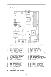
1.4 Motherboard Layout USB 3.0 Ps2 T: USB1 Keyboard B: USB2 /Mouse 1 ATX12V1 23 4 56 ...BASS LINE IN REAR SPK FRONT XFast LAN Top: Center: Bottom: MIC IN 41 CHA_FAN2 40 PCIE1 FM2A85X Extreme6 Front USB 3.0 39 PCIE2 LAN DX11 CMOS Dual Graphics 38 PCIE3 BATTERY AMD A85X 11 37 Super ...pin DDR3 DIMM Slots (Dual Channel A: DDR3_A1, DDR3_B1) 8 2 x 240-pin DDR3 DIMM Slots (Dual Channel B: DDR3_A2, DDR3_B2) 9 ATX Power Connector (ATXPWR1) 10 USB 3.0 Header (USB3_5_6) 11 Southbridge Controller 12 SATA3 Connectors (SATA3_1_2) 13 SATA3 Connectors (SATA3_3_4) 14 SATA3 Connectors...
1.4 Motherboard Layout USB 3.0 Ps2 T: USB1 Keyboard B: USB2 /Mouse 1 ATX12V1 23 4 56 ...BASS LINE IN REAR SPK FRONT XFast LAN Top: Center: Bottom: MIC IN 41 CHA_FAN2 40 PCIE1 FM2A85X Extreme6 Front USB 3.0 39 PCIE2 LAN DX11 CMOS Dual Graphics 38 PCIE3 BATTERY AMD A85X 11 37 Super ...pin DDR3 DIMM Slots (Dual Channel A: DDR3_A1, DDR3_B1) 8 2 x 240-pin DDR3 DIMM Slots (Dual Channel B: DDR3_A2, DDR3_B2) 9 ATX Power Connector (ATXPWR1) 10 USB 3.0 Header (USB3_5_6) 11 Southbridge Controller 12 SATA3 Connectors (SATA3_1_2) 13 SATA3 Connectors (SATA3_3_4) 14 SATA3 Connectors...

User Manual
Page 17
... wall socket before touching any motherboard settings. Pre-installation Precautions Take note of your motherboard directly on a grounded antistatic pad or in the bag that the power is switched off or the power cord is an ATX form factor motherboard. Whenever you handle components. ...3. 2. To avoid damaging the motherboard components due to static electricity, NEVER place your chassis to ensure that the motherboard fits into the screw holes to secure the motherboard to use a grounded wrist...
... wall socket before touching any motherboard settings. Pre-installation Precautions Take note of your motherboard directly on a grounded antistatic pad or in the bag that the power is switched off or the power cord is an ATX form factor motherboard. Whenever you handle components. ...3. 2. To avoid damaging the motherboard components due to static electricity, NEVER place your chassis to ensure that the motherboard fits into the screw holes to secure the motherboard to use a grounded wrist...
User Manual
Page 32
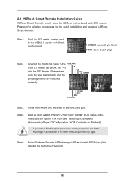
... make sure the wire assignments and the USB_PWR PP+ GND DUMMY pin assignments are matched correctly. 1 23 45 GND IRTX IRRX ATX+5VSB Step3. Step4. Execute ASRock support CD and install CIR Driver. (It is listed at [Enabled]. (Advanced -> Super IO Configuration -> CIR Controller -> [... up your system and install Multi-Angle CIR Receiver to the USB 2.0 header (as below procedures for ASRock motherboard with CIR header. 2.8 ASRock Smart Remote Installation Guide ASRock Smart Remote is only used for the quick installation and usage of driver list.) 32 Please refer to the...
... make sure the wire assignments and the USB_PWR PP+ GND DUMMY pin assignments are matched correctly. 1 23 45 GND IRTX IRRX ATX+5VSB Step3. Step4. Execute ASRock support CD and install CIR Driver. (It is listed at [Enabled]. (Advanced -> Super IO Configuration -> CIR Controller -> [... up your system and install Multi-Angle CIR Receiver to the USB 2.0 header (as below procedures for ASRock motherboard with CIR header. 2.8 ASRock Smart Remote Installation Guide ASRock Smart Remote is only used for the quick installation and usage of driver list.) 32 Please refer to the...

User Manual
Page 38
... connect the 3-Pin CPU fan to the CPU fan connector on this motherboard, please connect it can still work successfully even without the fan speed control function. CHA_FAN1/2/3 fan speed can work if you adopt a traditional 20-pin ATX power supply. Pin 1-3 Connected 3-Pin Fan Installation (3-pin CPU_FAN2) (... supply, please plug your power supply along with Pin 1 and Pin 13. 20-Pin ATX Power Supply Installation 1 13 38 Though this motherboard provides 4-Pin CPU fan (Quiet Fan) support, the 3-Pin CPU fan still can be controlled through UEFI or AXTU. (3-pin CHA_FAN3) (see p.14...
... connect the 3-Pin CPU fan to the CPU fan connector on this motherboard, please connect it can still work successfully even without the fan speed control function. CHA_FAN1/2/3 fan speed can work if you adopt a traditional 20-pin ATX power supply. Pin 1-3 Connected 3-Pin Fan Installation (3-pin CPU_FAN2) (... supply, please plug your power supply along with Pin 1 and Pin 13. 20-Pin ATX Power Supply Installation 1 13 38 Though this motherboard provides 4-Pin CPU fan (Quiet Fan) support, the 3-Pin CPU fan still can be controlled through UEFI or AXTU. (3-pin CHA_FAN3) (see p.14...

User Manual
Page 39
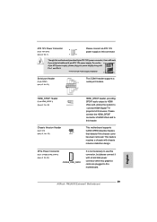
...p.14 No. 42) CROSS_FIRE_PWR1 It is not necessary to use the 4 8 4-pin ATX power supply, please plug your power supply along with chassis intrusion detection design. Though this motherboard. 39 Please connect the HDMI_SPDIF connector of HDMI VGA card to this connector. HDMI_SPDIF Header...connect it with a hard disk power connecor when two graphics cards are plugged to this motherboard provides 8-pin ATX 12V power connector, it can still work if you adopt a traditional 4-pin ATX 12V power supply. ATX 12V Power Connector 4 8 (8-pin ATX12V1) (see p.14 No. 1) 1 5...
...p.14 No. 42) CROSS_FIRE_PWR1 It is not necessary to use the 4 8 4-pin ATX power supply, please plug your power supply along with chassis intrusion detection design. Though this motherboard. 39 Please connect the HDMI_SPDIF connector of HDMI VGA card to this connector. HDMI_SPDIF Header...connect it with a hard disk power connecor when two graphics cards are plugged to this motherboard provides 8-pin ATX 12V power connector, it can still work if you adopt a traditional 4-pin ATX 12V power supply. ATX 12V Power Connector 4 8 (8-pin ATX12V1) (see p.14 No. 1) 1 5...
Quick Installation Guide
Page 2
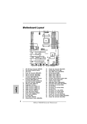
... (CPU_FAN1) 6 CPU Fan Connector (CPU_FAN2) 7 2 x 240-pin DDR3 DIMM Slots (Dual Channel A: DDR3_A1, DDR3_B1) 8 2 x 240-pin DDR3 DIMM Slots (Dual Channel B: DDR3_A2, DDR3_B2) 9 ATX Power Connector (ATXPWR1) 10 USB 3.0 Header (USB3_5_6) 11 Southbridge Controller 12 SATA3 Connectors (SATA3_1_2) 13 SATA3 Connectors (SATA3_3_4) 14 SATA3 Connectors (SATA3_7_8) 15 SATA3 Connector...2.0 x16 Slot (PCIE2) 40 PCI Express 2.0 x1 Slot (PCIE1) 41 Chassis Fan Connector (CHA_FAN2) 42 XFire Power Connector (CROSS_FIRE_PWR1) 43 Chassis Fan Connector (CHA_FAN3) 2 ASRock FM2A85X Extreme6 Motherboard English
... (CPU_FAN1) 6 CPU Fan Connector (CPU_FAN2) 7 2 x 240-pin DDR3 DIMM Slots (Dual Channel A: DDR3_A1, DDR3_B1) 8 2 x 240-pin DDR3 DIMM Slots (Dual Channel B: DDR3_A2, DDR3_B2) 9 ATX Power Connector (ATXPWR1) 10 USB 3.0 Header (USB3_5_6) 11 Southbridge Controller 12 SATA3 Connectors (SATA3_1_2) 13 SATA3 Connectors (SATA3_3_4) 14 SATA3 Connectors (SATA3_7_8) 15 SATA3 Connector...2.0 x16 Slot (PCIE2) 40 PCI Express 2.0 x1 Slot (PCIE1) 41 Chassis Fan Connector (CHA_FAN2) 42 XFire Power Connector (CROSS_FIRE_PWR1) 43 Chassis Fan Connector (CHA_FAN3) 2 ASRock FM2A85X Extreme6 Motherboard English

Quick Installation Guide
Page 5
... ASRock FM2A85X Extreme6 motherboard, a reliable motherboard produced under ASRock's consistently stringent quality control. Because the motherboard specifications and the BIOS software might be available on ASRock website as well. This Quick Installation Guide contains introduction of this motherboard, please visit our website for details. 5 ASRock FM2A85X Extreme6 Motherboard English www.asrock.com/support/index.asp 1.1 Package Contents ASRock FM2A85X Extreme6 Motherboard (ATX Form Factor) ASRock FM2A85X Extreme6 Quick Installation Guide ASRock FM2A85X Extreme6...
... ASRock FM2A85X Extreme6 motherboard, a reliable motherboard produced under ASRock's consistently stringent quality control. Because the motherboard specifications and the BIOS software might be available on ASRock website as well. This Quick Installation Guide contains introduction of this motherboard, please visit our website for details. 5 ASRock FM2A85X Extreme6 Motherboard English www.asrock.com/support/index.asp 1.1 Package Contents ASRock FM2A85X Extreme6 Motherboard (ATX Form Factor) ASRock FM2A85X Extreme6 Quick Installation Guide ASRock FM2A85X Extreme6...

Quick Installation Guide
Page 6
...- 2 x PCI Express 2.0 x1 slots - 2 x PCI slots - resolution up to 1920x1200 @ 60Hz - resolution up to 1920x1600 @ 60Hz - Supports DP++ 6 ASRock FM2A85X Extreme6 Motherboard English Digi Power Design - 8 + 2 Power Phase Design - Max. Supports AMD Memory Profile (AMP) - 3 x PCI Express 2.0 x16 slots (PCIE2/... two DIMMs - resolution up to 4096x2160 @ 30Hz - 1.2 Specifications Platform CPU Chipset Memory Expansion Slot Graphics - ATX Form Factor - Premium Gold Capacitor design (100% Japan-made high-quality Conductive Polymer Capacitors) - Support for Socket FM2 100W...
...- 2 x PCI Express 2.0 x1 slots - 2 x PCI slots - resolution up to 1920x1200 @ 60Hz - resolution up to 1920x1600 @ 60Hz - Supports DP++ 6 ASRock FM2A85X Extreme6 Motherboard English Digi Power Design - 8 + 2 Power Phase Design - Max. Supports AMD Memory Profile (AMP) - 3 x PCI Express 2.0 x16 slots (PCIE2/... two DIMMs - resolution up to 4096x2160 @ 30Hz - 1.2 Specifications Platform CPU Chipset Memory Expansion Slot Graphics - ATX Form Factor - Premium Gold Capacitor design (100% Japan-made high-quality Conductive Polymer Capacitors) - Support for Socket FM2 100W...

Quick Installation Guide
Page 8
...with LED - 64Mb AMI UEFI Legal BIOS with GUI support - Explorer, AMD Fusion, CyberLink MediaEspresso 6.5 Trial, ASRock MAGIX Multimedia Suite - CPU Quiet Fan - Voltage Monitoring: +12V, +5V, +3.3V, Vcore ASRock FM2A85X Extreme6 Motherboard Supports "Plug and Play" - Drivers, Utilities, AntiVirus Software (Trial Version), AMD Live! CPU Temperature Sensing -... - 1 x Chassis Intrusion header - 2 x CPU Fan connectors (1 x 4-pin, 1 x 3-pin) - 3 x Chassis Fan connectors (1 x 4-pin, 2 x 3-pin) - 1 x Power Fan connector (3-pin) - 24 pin ATX power connector - 8 pin 12V power connector -
...with LED - 64Mb AMI UEFI Legal BIOS with GUI support - Explorer, AMD Fusion, CyberLink MediaEspresso 6.5 Trial, ASRock MAGIX Multimedia Suite - CPU Quiet Fan - Voltage Monitoring: +12V, +5V, +3.3V, Vcore ASRock FM2A85X Extreme6 Motherboard Supports "Plug and Play" - Drivers, Utilities, AntiVirus Software (Trial Version), AMD Live! CPU Temperature Sensing -... - 1 x Chassis Intrusion header - 2 x CPU Fan connectors (1 x 4-pin, 1 x 3-pin) - 3 x Chassis Fan connectors (1 x 4-pin, 2 x 3-pin) - 1 x Power Fan connector (3-pin) - 24 pin ATX power connector - 8 pin 12V power connector -

Quick Installation Guide
Page 14
...it . Doing so may cause severe damage to do so may damage the motherboard. 14 ASRock FM2A85X Extreme6 Motherboard English Failure to the motherboard, peripherals, and/or components. 1. Pre-installation Precautions Take note of your motherboard directly on a grounded antistatic pad or in the bag that comes with ... handle components. 3. 2. To avoid damaging the motherboard components due to static electricity, NEVER place your chassis to ensure that the power is switched off or the power cord is an ATX form factor motherboard. Hold components by the edges and do not over...
...it . Doing so may cause severe damage to do so may damage the motherboard. 14 ASRock FM2A85X Extreme6 Motherboard English Failure to the motherboard, peripherals, and/or components. 1. Pre-installation Precautions Take note of your motherboard directly on a grounded antistatic pad or in the bag that comes with ... handle components. 3. 2. To avoid damaging the motherboard components due to static electricity, NEVER place your chassis to ensure that the power is switched off or the power cord is an ATX form factor motherboard. Hold components by the edges and do not over...

Quick Installation Guide
Page 28
... work successfully even without the fan speed control function. To use the 20-pin ATX power supply, please plug your power supply along with Pin 1 and Pin 13. 20-Pin ATX Power Supply Installation 1 13 English 28 ASRock FM2A85X Extreme6 Motherboard Though this motherboard, please connect it to Pin 1-3. Pin 1-3 Connected 3-Pin Fan Installation (3-pin CPU_FAN2) (see...
... work successfully even without the fan speed control function. To use the 20-pin ATX power supply, please plug your power supply along with Pin 1 and Pin 13. 20-Pin ATX Power Supply Installation 1 13 English 28 ASRock FM2A85X Extreme6 Motherboard Though this motherboard, please connect it to Pin 1-3. Pin 1-3 Connected 3-Pin Fan Installation (3-pin CPU_FAN2) (see...
Quick Installation Guide
Page 29
... power connecor when two graphics cards are plugged to this connector. English 29 ASRock FM2A85X Extreme6 Motherboard HDMI_SPDIF Header (2-pin HDMI_SPDIF1) (see p.2 No. 32) Chassis Intrusion Header (2-pin CI1) (see p.2 No. 1) 4 8 1 5 Please connect an ATX 12V power supply to this motherboard. This motherboard supports CASE OPEN detection feature that detects if the chassis cover has been removed...
... power connecor when two graphics cards are plugged to this connector. English 29 ASRock FM2A85X Extreme6 Motherboard HDMI_SPDIF Header (2-pin HDMI_SPDIF1) (see p.2 No. 32) Chassis Intrusion Header (2-pin CI1) (see p.2 No. 1) 4 8 1 5 Please connect an ATX 12V power supply to this motherboard. This motherboard supports CASE OPEN detection feature that detects if the chassis cover has been removed...

Quick Installation Guide
Page 129
...AMD Live! CPU 계 - Explorer, AMD Fusion, CyberLink MediaEspresso 6.5 ASRock MAGIX Multimedia Suite - CPU - FCC, CE, WHQL - ACPI 1.1 ...ATX - 8 핀 ATX 12V - LED 1 개 BIOS - 64Mb GUI AMI UEFI 적합형 BIOS - LED 1 개 - CPU 12V,+5V,+3.3V,Vcore OS Windows® 8/8 64 비트 /7/7 64 비트 /VistaTM/ VistaTM 64 인증서 - ErP/EuP 지원 (ErP/EuP http://www.asrock.com 한 국 어 129 ASRock FM2A85X Extreme6 Motherboard...
...AMD Live! CPU 계 - Explorer, AMD Fusion, CyberLink MediaEspresso 6.5 ASRock MAGIX Multimedia Suite - CPU - FCC, CE, WHQL - ACPI 1.1 ...ATX - 8 핀 ATX 12V - LED 1 개 BIOS - 64Mb GUI AMI UEFI 적합형 BIOS - LED 1 개 - CPU 12V,+5V,+3.3V,Vcore OS Windows® 8/8 64 비트 /7/7 64 비트 /VistaTM/ VistaTM 64 인증서 - ErP/EuP 지원 (ErP/EuP http://www.asrock.com 한 국 어 129 ASRock FM2A85X Extreme6 Motherboard...

Quick Installation Guide
Page 134
... GND PWR_FAN_SPEED CPU (4 핀 CPU_FAN1) (2 5 FAN_SPEED_CONTROL CPU_FAN_SPEED +12V GND CPU 1 2 3 4 4 핀 CPU 3 핀 CPU CPU 3 핀 CPU 1-3 1-3 3 (3 핀 CPU_FAN2) (2 6 GND +12V CPU_FAN_SPEED 한 국 어 ATX (24 핀 ATXPWR1) (2 9 12 24 ATX 1 13 24 핀 ATX 12 24 종래의 20 핀 ATX 20 핀 ATX Pin 1 과 Pin 13 20 핀 ATX 1 13 134 ASRock FM2A85X Extreme6 Motherboard
... GND PWR_FAN_SPEED CPU (4 핀 CPU_FAN1) (2 5 FAN_SPEED_CONTROL CPU_FAN_SPEED +12V GND CPU 1 2 3 4 4 핀 CPU 3 핀 CPU CPU 3 핀 CPU 1-3 1-3 3 (3 핀 CPU_FAN2) (2 6 GND +12V CPU_FAN_SPEED 한 국 어 ATX (24 핀 ATXPWR1) (2 9 12 24 ATX 1 13 24 핀 ATX 12 24 종래의 20 핀 ATX 20 핀 ATX Pin 1 과 Pin 13 20 핀 ATX 1 13 134 ASRock FM2A85X Extreme6 Motherboard

Quick Installation Guide
Page 135
ATX 12V (8 핀 ATX12V1) (2 1 4 8 1 5 ATX 12V 8- 핀 ATX 12V 4- 핀 ATX 12V 용하여 4- 핀 ATX 1 과 핀 5 4 8 4- 핀 ATX 12V 1 5 (9 핀 COM1) (2 31 HDMI_SPDIF 헤더 (2 핀 HDMI_SPDIF1) (2 32 (2 핀 CI1) (2 30 1 GND Signal HDMI VGA 카드에 SPDIF HDMI_SPDIF HDMI 디지털 TV LCD HDMI VGA 카드의 HDMI_SPDIF 한국어 135 ASRock FM2A85X Extreme6 Motherboard
ATX 12V (8 핀 ATX12V1) (2 1 4 8 1 5 ATX 12V 8- 핀 ATX 12V 4- 핀 ATX 12V 용하여 4- 핀 ATX 1 과 핀 5 4 8 4- 핀 ATX 12V 1 5 (9 핀 COM1) (2 31 HDMI_SPDIF 헤더 (2 핀 HDMI_SPDIF1) (2 32 (2 핀 CI1) (2 30 1 GND Signal HDMI VGA 카드에 SPDIF HDMI_SPDIF HDMI 디지털 TV LCD HDMI VGA 카드의 HDMI_SPDIF 한국어 135 ASRock FM2A85X Extreme6 Motherboard

Quick Installation Guide
Page 139
...-Streaming 12bpc)、xvYCC、HBR(High Bit Rate HDMI (HDMI 139 ASRock FM2A85X Extreme6 Motherboard 日本語 DDR3 2600+(OC)/2400(OC)/2133(OC)/1866/1600/1333/ 1066/800 non-ECC, un-buffered 32GB - ATX 100 Socket FM2 100W Processors 8 + 2 AMD 社 Cool 'n' QuietTM UMI-Link GEN2 - AMD A85X (Hudson...
...-Streaming 12bpc)、xvYCC、HBR(High Bit Rate HDMI (HDMI 139 ASRock FM2A85X Extreme6 Motherboard 日本語 DDR3 2600+(OC)/2400(OC)/2133(OC)/1866/1600/1333/ 1066/800 non-ECC, un-buffered 32GB - ATX 100 Socket FM2 100W Processors 8 + 2 AMD 社 Cool 'n' QuietTM UMI-Link GEN2 - AMD A85X (Hudson...

Quick Installation Guide
Page 147
...;照 4 8 1 5 CPU に Vcore ATX 12V 8-pin ATX 12V 4-pin ATX 12V 4-pin ATX Pin 1 と Pin 5 4 8 4-Pin ATX 12V 1 5 9 ピン COM1 31 を参照 この COM1 日本語 HDMI_SPDIF ヘッダ (2- ピン HDMI_SPDIF1 32 を参照 HDMI_SPDIF SPDIF HDMI VGA HDMI TV LCD HDMI VGA HDMI_SPDIF 147 ASRock FM2A85X Extreme6 Motherboard
...;照 4 8 1 5 CPU に Vcore ATX 12V 8-pin ATX 12V 4-pin ATX 12V 4-pin ATX Pin 1 と Pin 5 4 8 4-Pin ATX 12V 1 5 9 ピン COM1 31 を参照 この COM1 日本語 HDMI_SPDIF ヘッダ (2- ピン HDMI_SPDIF1 32 を参照 HDMI_SPDIF SPDIF HDMI VGA HDMI TV LCD HDMI VGA HDMI_SPDIF 147 ASRock FM2A85X Extreme6 Motherboard

Quick Installation Guide
Page 150
1 FM2A85X Extreme6 BIOS CPU http://www.asrock.com www.asrock.com/support/index.asp 1.1 華擎 FM2A85X Extreme6 主板 (ATX FM2A85X Extreme6 FM2A85X Extreme6 Serial ATA(SATA I/O 擋板 ASRock 為了在 Windows® 8 / 8 64-bit / 7 / 7 64-bit / VistaTM / VistaTM 64bit BIOS中將Storage Configuration AHCI BIOS User Manual 150 ASRock FM2A85X Extreme6 Motherboard 簡體中文
1 FM2A85X Extreme6 BIOS CPU http://www.asrock.com www.asrock.com/support/index.asp 1.1 華擎 FM2A85X Extreme6 主板 (ATX FM2A85X Extreme6 FM2A85X Extreme6 Serial ATA(SATA I/O 擋板 ASRock 為了在 Windows® 8 / 8 64-bit / 7 / 7 64-bit / VistaTM / VistaTM 64bit BIOS中將Storage Configuration AHCI BIOS User Manual 150 ASRock FM2A85X Extreme6 Motherboard 簡體中文

Quick Installation Guide
Page 153
...;欄 - FCC, CE, WHQL - 支持 ErP/EuP ErP/EuP http://www.asrock.com 簡體中文 153 ASRock FM2A85X Extreme6 Motherboard CPU 12V、+5V、+3.3V 操作系統 - AMI UEFI Legal BIOS,... Dr. Debug (7 段調試 LED) - 1 個帶 LED - 1 個帶 LED BIOS - 64Mb AMI BIOS - - 1 x 3 針 ) - 24 針 ATX - 8 針 12V - DRAM、APU PCIE VDDP、CPU 和 CPU NB/GFX 支持光盤 AMD Live! CPU - CPU -
...;欄 - FCC, CE, WHQL - 支持 ErP/EuP ErP/EuP http://www.asrock.com 簡體中文 153 ASRock FM2A85X Extreme6 Motherboard CPU 12V、+5V、+3.3V 操作系統 - AMI UEFI Legal BIOS,... Dr. Debug (7 段調試 LED) - 1 個帶 LED - 1 個帶 LED BIOS - 64Mb AMI BIOS - - 1 x 3 針 ) - 24 針 ATX - 8 針 12V - DRAM、APU PCIE VDDP、CPU 和 CPU NB/GFX 支持光盤 AMD Live! CPU - CPU -

