User Manual
Page 2
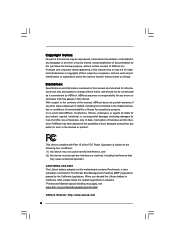
... means, except duplication of documentation by the purchaser for backup purpose, without written consent of ASRock Inc. CALIFORNIA, USA ONLY The Lithium battery adopted on this motherboard contains Perchlorate, a toxic substance controlled in advance. Products and corporate names appearing in this ...the manual or product. Disclaimer: Specifications and information contained in this manual are used only for a particular purpose. ASRock assumes no event shall ASRock, its directors, officers, employees, or agents be registered trademarks or copyrights of their respective companies, and are ...
... means, except duplication of documentation by the purchaser for backup purpose, without written consent of ASRock Inc. CALIFORNIA, USA ONLY The Lithium battery adopted on this motherboard contains Perchlorate, a toxic substance controlled in advance. Products and corporate names appearing in this ...the manual or product. Disclaimer: Specifications and information contained in this manual are used only for a particular purpose. ASRock assumes no event shall ASRock, its directors, officers, employees, or agents be registered trademarks or copyrights of their respective companies, and are ...

User Manual
Page 3
... 5 1.1 Package Contents 5 1.2 Specifications 6 1.3 Minimum Hardware Requirement Table for Windows® VistaTM Premium 2007 and Basic Logo 9 1.4 Motherboard Layout 10 1.5 HD 8CH I/O 11 2 Installation 12 2.1 Screw Holes 12 2.2 Pre-installation Precautions 12 2.3 CPU Installation 13 2.4 Installation...and CPU fan 15 2.5 Installation of Memory Modules (DIMM 16 2.6 Expansion Slots (PCI, HDMR, and PCI Express Slots) ....... 18 2.7 DVI Graphics-HDCP Card Installation Guide 19 2.8 Jumpers Setup 21 2.9 Onboard Headers and Connectors 22 2.10 SATAII Hard Disk Setup Guide 26 2.11 Serial...
... 5 1.1 Package Contents 5 1.2 Specifications 6 1.3 Minimum Hardware Requirement Table for Windows® VistaTM Premium 2007 and Basic Logo 9 1.4 Motherboard Layout 10 1.5 HD 8CH I/O 11 2 Installation 12 2.1 Screw Holes 12 2.2 Pre-installation Precautions 12 2.3 CPU Installation 13 2.4 Installation...and CPU fan 15 2.5 Installation of Memory Modules (DIMM 16 2.6 Expansion Slots (PCI, HDMR, and PCI Express Slots) ....... 18 2.7 DVI Graphics-HDCP Card Installation Guide 19 2.8 Jumpers Setup 21 2.9 Onboard Headers and Connectors 22 2.10 SATAII Hard Disk Setup Guide 26 2.11 Serial...

User Manual
Page 5
... guide to change without further notice. ASRock website http://www.asrock.com 1.1 Package Contents ASRock ConRoe1333-DVI/H Motherboard (Micro ATX Form Factor: 9.6-in x 9.6-in, 24.4 cm x 24.4 cm) ASRock ConRoe1333-DVI/H Quick Installation Guide ASRock ConRoe1333-DVI/H Support CD One 80-conductor Ultra ATA 66/100 IDE Ribbon Cable One Ribbon Cable for purchasing ASRock ConRoe1333-DVI/H motherboard, a reliable motherboard produced under ASRock's consistently stringent quality control. In...
... guide to change without further notice. ASRock website http://www.asrock.com 1.1 Package Contents ASRock ConRoe1333-DVI/H Motherboard (Micro ATX Form Factor: 9.6-in x 9.6-in, 24.4 cm x 24.4 cm) ASRock ConRoe1333-DVI/H Quick Installation Guide ASRock ConRoe1333-DVI/H Support CD One 80-conductor Ultra ATA 66/100 IDE Ribbon Cable One Ribbon Cable for purchasing ASRock ConRoe1333-DVI/H motherboard, a reliable motherboard produced under ASRock's consistently stringent quality control. In...
User Manual
Page 8
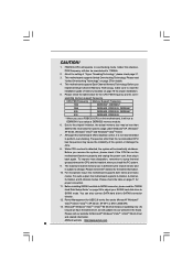
...16 for details. 4. Before you implement Dual Channel Memory Technology, make sure to read "Untied Overclocking Technology" on this motherboard, it is detected, the system will operate in the future. While CPU overheat is not recommended to 115MHz. 2. Please...11. Although this situation, PCIE frequency will update it back again. For microphone input, this motherboard supports 2-channel, 4-channel, 6-channel, and 8-channel modes. ASRock website http://www.asrock.com 8 CAUTION! 1. Frequencies other than the recommended CPU bus frequencies may be overclocked to...
...16 for details. 4. Before you implement Dual Channel Memory Technology, make sure to read "Untied Overclocking Technology" on this motherboard, it is detected, the system will operate in the future. While CPU overheat is not recommended to 115MHz. 2. Please...11. Although this situation, PCIE frequency will update it back again. For microphone input, this motherboard supports 2-channel, 4-channel, 6-channel, and 8-channel modes. ASRock website http://www.asrock.com 8 CAUTION! 1. Frequencies other than the recommended CPU bus frequencies may be overclocked to...
User Manual
Page 9
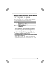
...174; VistaTM Premium 2007 and Basic Logo For system integrators and users who purchase this motherboard, please refer to Premium Discrete requirement at http://www.asrock.com * If the onboard VGA supports DVI, it must also support HDCP function to qualify for Windows® VistaTM Premium 2007 logo...Dual Channel (Premium) 512MB Single Channel (Basic) 256MB x 2 Dual Channel (Basic) DX9.0 with VDDM Driver DVI with HDCP * If you plan to use external graphics card on this motherboard and plan to submit Windows® VistaTM Premium 2007 and Basic logo, please follow below table for Windows®...
...174; VistaTM Premium 2007 and Basic Logo For system integrators and users who purchase this motherboard, please refer to Premium Discrete requirement at http://www.asrock.com * If the onboard VGA supports DVI, it must also support HDCP function to qualify for Windows® VistaTM Premium 2007 logo...Dual Channel (Premium) 512MB Single Channel (Basic) 256MB x 2 Dual Channel (Basic) DX9.0 with VDDM Driver DVI with HDCP * If you plan to use external graphics card on this motherboard and plan to submit Windows® VistaTM Premium 2007 and Basic logo, please follow below table for Windows®...

User Manual
Page 10
...Yellow) 22 Front Panel Audio Header (HD_AUDIO1) 8 2 x 240-pin DDRII DIMM Slots 23 PCI Slots (PCI1- 2) (Dual Channel B: DDRII_2, DDRII_4; 1.4 Motherboard Layout 1 23 PS2 Mouse 1 PS2_USB_PWR1 CPU_FAN1 PS2 Keyboard ATX12V1 4 24.4cm (9.6 in) 5 67 8 CLRCMOS1 CMOS Battery PARALLEL PORT DDRII_4 (64/72 bit,...1 USB6_7 SATAII_3 SATAII_1 USB2.0 CHA_FAN1 SATAII_4 SATAII_2 SPEAKER1 1 PANEL 1 PLED PWRBTN 1 HDLED RESET Dual Core CPU Dual Channel ConRoe1333-DVI/H 22 21 20 19 18 17 161514 13 DDRII667 24.4cm (9.6 in) 9 10 11 12 1 PS2_USB_PWR1 Jumper 15 Third SATAII Connector (SATAII_3...
...Yellow) 22 Front Panel Audio Header (HD_AUDIO1) 8 2 x 240-pin DDRII DIMM Slots 23 PCI Slots (PCI1- 2) (Dual Channel B: DDRII_2, DDRII_4; 1.4 Motherboard Layout 1 23 PS2 Mouse 1 PS2_USB_PWR1 CPU_FAN1 PS2 Keyboard ATX12V1 4 24.4cm (9.6 in) 5 67 8 CLRCMOS1 CMOS Battery PARALLEL PORT DDRII_4 (64/72 bit,...1 USB6_7 SATAII_3 SATAII_1 USB2.0 CHA_FAN1 SATAII_4 SATAII_2 SPEAKER1 1 PANEL 1 PLED PWRBTN 1 HDLED RESET Dual Core CPU Dual Channel ConRoe1333-DVI/H 22 21 20 19 18 17 161514 13 DDRII667 24.4cm (9.6 in) 9 10 11 12 1 PS2_USB_PWR1 Jumper 15 Third SATAII Connector (SATAII_3...

User Manual
Page 12
...ConRoe1333-DVI/H is detached from the wall socket before touching any component, ensure that the power is switched off or the power cord is a Micro ATX form factor (9.6" x 9.6", 24.4 x 24.4 cm) motherboard. Also remember to use a grounded wrist strap or touch a safety grounded object before you and damages to motherboard... the ICs. 4. Before you uninstall any motherboard settings. 1. To avoid damaging the motherboard components due to static electricity, NEVER place your chassis to unplug the power cord before you install motherboard components or change any component, place it ...
...ConRoe1333-DVI/H is detached from the wall socket before touching any component, ensure that the power is switched off or the power cord is a Micro ATX form factor (9.6" x 9.6", 24.4 x 24.4 cm) motherboard. Also remember to use a grounded wrist strap or touch a safety grounded object before you and damages to motherboard... the ICs. 4. Before you uninstall any motherboard settings. 1. To avoid damaging the motherboard components due to static electricity, NEVER place your chassis to unplug the power cord before you install motherboard components or change any component, place it ...
User Manual
Page 14
... thumb and peel the cap from the socket while pressing on load plate, engage the load lever. This cap must be placed if returning the motherboard for after service. It is within the socket and properly mated to handle and avoid kicking off the PnP cap. 2. Close the socket: Step 4-1. Step...
... thumb and peel the cap from the socket while pressing on load plate, engage the load lever. This cap must be placed if returning the motherboard for after service. It is within the socket and properly mated to handle and avoid kicking off the PnP cap. 2. Close the socket: Step 4-1. Step...
User Manual
Page 15
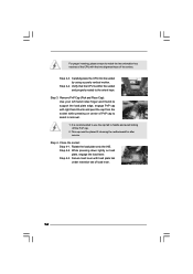
... with fan operation or contact other . Repeat with Intel 775-LAND CPU to dissipate heat. 2.4 Installation of CPU Fan and Heatsink This motherboard is an example to illustrate the installation of your CPU fan and heatsink. Step 3. Step 6. If you need to spray thermal interface ...the socket surface. Rotate the fastener clockwise, then press down the fasteners without rotating them clockwise, the heatsink cannot be secured on the motherboard (CPU_FAN1, see page 10, No. 3). Ensure that supports Intel 775-LAND CPU. Apply thermal interface material onto center of heatsink and...
... with fan operation or contact other . Repeat with Intel 775-LAND CPU to dissipate heat. 2.4 Installation of CPU Fan and Heatsink This motherboard is an example to illustrate the installation of your CPU fan and heatsink. Step 3. Step 6. If you need to spray thermal interface ...the socket surface. Rotate the fastener clockwise, then press down the fasteners without rotating them clockwise, the heatsink cannot be secured on the motherboard (CPU_FAN1, see page 10, No. 3). Ensure that supports Intel 775-LAND CPU. Apply thermal interface material onto center of heatsink and...

User Manual
Page 16
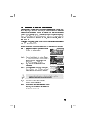
... have to install a DDR memory module into DDRII slot; 2.5 Installation of orange slots (DDRII_2 and DDRII_4). 2. Orange slots; otherwise, this motherboard, it is not allowed to install identical DDRII DIMM pair in all four slots. 1. In other words, install them in Dual Channel B ...(Orange Slot) (1) Populated - If only one memory module or three memory modules are installed in the set of Memory Modules (DIMM) ConRoe1333-DVI/H motherboard provides four 240-pin DDRII (Double Data Rate II) DIMM slots, and supports Dual Channel Memory Technology. It is recommended to install two ...
... have to install a DDR memory module into DDRII slot; 2.5 Installation of orange slots (DDRII_2 and DDRII_4). 2. Orange slots; otherwise, this motherboard, it is not allowed to install identical DDRII DIMM pair in all four slots. 1. In other words, install them in Dual Channel B ...(Orange Slot) (1) Populated - If only one memory module or three memory modules are installed in the set of Memory Modules (DIMM) ConRoe1333-DVI/H motherboard provides four 240-pin DDRII (Double Data Rate II) DIMM slots, and supports Dual Channel Memory Technology. It is recommended to install two ...
User Manual
Page 17
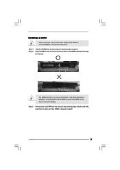
... the DIMM is properly seated. 17 Step 2. Unlock a DIMM slot by pressing the retaining clips outward. Step 1. Step 3. Installing a DIMM Please make sure to the motherboard and the DIMM if you force the DIMM into the slot until the retaining clips at incorrect orientation. It will cause permanent damage to disconnect...
... the DIMM is properly seated. 17 Step 2. Unlock a DIMM slot by pressing the retaining clips outward. Step 1. Step 3. Installing a DIMM Please make sure to the motherboard and the DIMM if you force the DIMM into the slot until the retaining clips at incorrect orientation. It will cause permanent damage to disconnect...

User Manual
Page 18
... There are used to insert a HDMR card with screws. 18 If you start the installation. You can only choose either PCI Express VGA card or DVI Graphics-HDCP card to install to the chassis with v.92 Modem functionality. Keep the screws for the card before you install the add-on this... motherboard. Step 3. Step 4. Please read the documentation of the expansion card and make sure that the power supply is switched off or the power cord is...
... There are used to insert a HDMR card with screws. 18 If you start the installation. You can only choose either PCI Express VGA card or DVI Graphics-HDCP card to install to the chassis with v.92 Modem functionality. Keep the screws for the card before you install the add-on this... motherboard. Step 3. Step 4. Please read the documentation of the expansion card and make sure that the power supply is switched off or the power cord is...
User Manual
Page 19
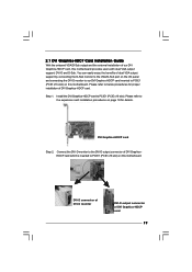
...DVI-D connector of DVI-D monitor DVI-D output connector of our DVI Graphics-HDCP card, this motherboard provides users with dual VGA output support: DVI-D and D-Sub. 2.7 DVI Graphics-HDCP Card Installation Guide With the onboard VGA/D-Sub output and the external installation of DVI Graphics-HDCP card 19 DVI Graphics-HDCP DVI Graphics-HDCP card Step 2. Install the DVI...installation of DVI Graphics-HDCP card. You can easily enjoy the benefits of DVI GraphicsHDCP card which is inserted to PCIE1 (PCIE x16 slot) on this motherboard. Connect the DVI-D monitor to the DVI-D output ...
...DVI-D connector of DVI-D monitor DVI-D output connector of our DVI Graphics-HDCP card, this motherboard provides users with dual VGA output support: DVI-D and D-Sub. 2.7 DVI Graphics-HDCP Card Installation Guide With the onboard VGA/D-Sub output and the external installation of DVI Graphics-HDCP card 19 DVI Graphics-HDCP DVI Graphics-HDCP card Step 2. Install the DVI...installation of DVI Graphics-HDCP card. You can easily enjoy the benefits of DVI GraphicsHDCP card which is inserted to PCIE1 (PCIE x16 slot) on this motherboard. Connect the DVI-D monitor to the DVI-D output ...
User Manual
Page 20
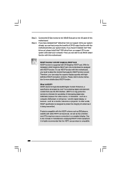
...® VGA driver yet, please install Intel® VGA driver from our support CD to eliminate the possibility of DVI-D output function with this motherboard after your computer. Therefore, you purchase is a copy protection scheme to your system already, you have installed Intel&#.... Step 4. such as a monitor, television or projector. Products compatible with HDCP function. What is being transmitted. To use DVI-D output function with this motherboard. In other words, HDCP specification is equipped with the HDCP scheme such as DVD players, satellite and cable HDTV set -top...
...® VGA driver yet, please install Intel® VGA driver from our support CD to eliminate the possibility of DVI-D output function with this motherboard after your computer. Therefore, you purchase is a copy protection scheme to your system already, you have installed Intel&#.... Step 4. such as a monitor, television or projector. Products compatible with HDCP function. What is being transmitted. To use DVI-D output function with this motherboard. In other words, HDCP specification is equipped with the HDCP scheme such as DVD players, satellite and cable HDTV set -top...
User Manual
Page 22
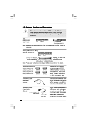
...-striped side of the cable is plugged into Pin1 side of the motherboard! Serial ATA (SATA) Power Cable (Optional) connect to the SATA HDD power connector connect to the power ...connector on the motherboard. FDD connector (33-pin FLOPPY1) (see p.10, No. 13) SATAII_1 SATAII_4 SATAII_2 These Serial... IDE1, see p.10 No. 10) PIN1 IDE1 connect the blue end connect the black end to the motherboard to the IDE devices 80-conductor ATA 66/100 cable Note: Please refer to the instruction of SATA power...
...-striped side of the cable is plugged into Pin1 side of the motherboard! Serial ATA (SATA) Power Cable (Optional) connect to the SATA HDD power connector connect to the power ...connector on the motherboard. FDD connector (33-pin FLOPPY1) (see p.10, No. 13) SATAII_1 SATAII_4 SATAII_2 These Serial... IDE1, see p.10 No. 10) PIN1 IDE1 connect the blue end connect the black end to the motherboard to the IDE devices 80-conductor ATA 66/100 cable Note: Please refer to the instruction of SATA power...
User Manual
Page 23
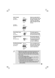
Connect Audio_R (RIN) to OUT2_R and Audio_L (LIN) to MIC2_L. MIC_RET and OUT_RET are two USB 2.0 headers on this motherboard. Connect Mic_IN (MIC) to OUT2_L. Enter BIOS Setup Utility. Enter Advanced Settings, and then select Chipset Configuration. Please follow the instruction in our manual and ...
Connect Audio_R (RIN) to OUT2_R and Audio_L (LIN) to MIC2_L. MIC_RET and OUT_RET are two USB 2.0 headers on this motherboard. Connect Mic_IN (MIC) to OUT2_L. Enter BIOS Setup Utility. Enter Advanced Settings, and then select Chipset Configuration. Please follow the instruction in our manual and ...
User Manual
Page 24
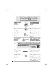
...CHA_FAN1) (see p.10 No. 17) GND +12V CHA_FAN_SPEED Please connect a chassis fan cable to this connector and match the black wire to this motherboard provides 4-Pin CPU fan (Quiet Fan) support, the 3-Pin CPU fan still can provides sufficient power. Pin 1-3 Connected 3-Pin Fan Installation ATX Power...GND 1 DUMMY RESET# GND HDLEDHDLED+ 1 SPEAKER DUMMY DUMMY +5V This header accommodates several system front panel functions. Click the icon on this motherboard, please connect it to this header. Failing to do so will cause the failure to enter Realtek HD Audio Manager. If you plan to ...
...CHA_FAN1) (see p.10 No. 17) GND +12V CHA_FAN_SPEED Please connect a chassis fan cable to this connector and match the black wire to this motherboard provides 4-Pin CPU fan (Quiet Fan) support, the 3-Pin CPU fan still can provides sufficient power. Pin 1-3 Connected 3-Pin Fan Installation ATX Power...GND 1 DUMMY RESET# GND HDLEDHDLED+ 1 SPEAKER DUMMY DUMMY +5V This header accommodates several system front panel functions. Click the icon on this motherboard, please connect it to this header. Failing to do so will cause the failure to enter Realtek HD Audio Manager. If you plan to ...

User Manual
Page 27
...those required drivers. Please follow the order from up to bottom side to your system can be auto-detected and listed on this motherboard, please follow the steps below then. 1. Reboot your optical drive first. This section will guide you apply Untied Overclocking Technology. ...27 STEP 4: Connect the other end of the SATA data cable to your system. 2.14 Untied Overclocking Technology This motherboard supports Untied Overclocking Technology, which means during overclocking, but in the fixed mode so that supports Serial ATA (SATA) / Serial ATAII (...
...those required drivers. Please follow the order from up to bottom side to your system can be auto-detected and listed on this motherboard, please follow the steps below then. 1. Reboot your optical drive first. This section will guide you apply Untied Overclocking Technology. ...27 STEP 4: Connect the other end of the SATA data cable to your system. 2.14 Untied Overclocking Technology This motherboard supports Untied Overclocking Technology, which means during overclocking, but in the fixed mode so that supports Serial ATA (SATA) / Serial ATAII (...
User Manual
Page 28
... SETUP UTILITY when you see on . The BIOS FWH chip on the system chassis. You may also restart by pressing the reset button on the motherboard stores the BIOS SETUP UTILITY. Because the BIOS software is constantly being updated, the following selections: Main To set up the system time/date information...
... SETUP UTILITY when you see on . The BIOS FWH chip on the system chassis. You may also restart by pressing the reset button on the motherboard stores the BIOS SETUP UTILITY. Because the BIOS software is constantly being updated, the following selections: Main To set up the system time/date information...
User Manual
Page 31
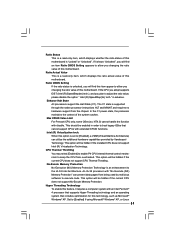
...pages from the chipset. If the CPU you adopt supports EIST (Intel (R) SpeedStep(tm) tech.), and you changing the ratio value of this motherboard. Enhance Halt State All processors support the Halt State (C1). The C1 state is supported through the native processor instructions HLT and MWAIT and requires... Throttling. This option will be hidden if the installed CPU does not support Intel (R) Virtualization Technology. Hyper Threading Technology To enable this motherboard is "Locked" or "Unlocked". This option will find this item appear to allow you changing the ratio value of this...
...pages from the chipset. If the CPU you adopt supports EIST (Intel (R) SpeedStep(tm) tech.), and you changing the ratio value of this motherboard. Enhance Halt State All processors support the Halt State (C1). The C1 state is supported through the native processor instructions HLT and MWAIT and requires... Throttling. This option will be hidden if the installed CPU does not support Intel (R) Virtualization Technology. Hyper Threading Technology To enable this motherboard is "Locked" or "Unlocked". This option will find this item appear to allow you changing the ratio value of this...

