User Manual
Page 3
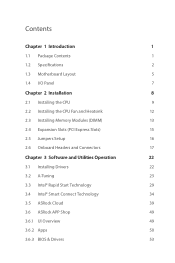
...1 1.2 Specifications 2 1.3 Motherboard Layout 5 1.4 I/O Panel 7 Chapter 2 Installation 8 2.1 Installing the CPU 9 2.2 Installing the CPU Fan and Heatsink 12 2.3 Installing Memory Modules (DIMM) 13 2.4 Expansion Slots (PCI Express Slots) 15 2.5 Jumpers Setup 16 2.6 Onboard Headers and Connectors 17 Chapter 3 Software and Utilities Operation 22 3.1 Installing Drivers 22 3.2 A-Tuning 23 3.3 Intel® Rapid Start Technology 29 3.4 Intel® Smart Connect Technology 34 3.5 ASRock Cloud 39 3.6 ASRock APP Shop 49 3.6.1 UI Overview 49 3.6.2 Apps 50 3.6.3 BIOS...
...1 1.2 Specifications 2 1.3 Motherboard Layout 5 1.4 I/O Panel 7 Chapter 2 Installation 8 2.1 Installing the CPU 9 2.2 Installing the CPU Fan and Heatsink 12 2.3 Installing Memory Modules (DIMM) 13 2.4 Expansion Slots (PCI Express Slots) 15 2.5 Jumpers Setup 16 2.6 Onboard Headers and Connectors 17 Chapter 3 Software and Utilities Operation 22 3.1 Installing Drivers 22 3.2 A-Tuning 23 3.3 Intel® Rapid Start Technology 29 3.4 Intel® Smart Connect Technology 34 3.5 ASRock Cloud 39 3.6 ASRock APP Shop 49 3.6.1 UI Overview 49 3.6.2 Apps 50 3.6.3 BIOS...

User Manual
Page 5
.... In case any modifications of this documentation occur, the updated version will be available on ASRock's website as well. Chapter 4 contains the configuration guide of the software and utilities. ASRock website http://www.asrock.com. 1.1 Package Contents • ASRock B85M-DGS Motherboard (Micro ATX Form Factor) • ASRock B85M-DGS Quick Installation Guide • ASRock B85M-DGS Support CD • 2 x Serial ATA (SATA) Data Cables (Optional) • 1 x I/O Panel Shield 1 English Chapter 3 contains the operation guide of the BIOS setup. If you are using...
.... In case any modifications of this documentation occur, the updated version will be available on ASRock's website as well. Chapter 4 contains the configuration guide of the software and utilities. ASRock website http://www.asrock.com. 1.1 Package Contents • ASRock B85M-DGS Motherboard (Micro ATX Form Factor) • ASRock B85M-DGS Quick Installation Guide • ASRock B85M-DGS Support CD • 2 x Serial ATA (SATA) Data Cables (Optional) • 1 x I/O Panel Shield 1 English Chapter 3 contains the operation guide of the BIOS setup. If you are using...

User Manual
Page 7
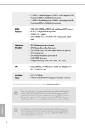
...; 2 x USB 3.0 Ports (Supports ESD Protection (ASRock Full Spike Protection)) • 1 x RJ-45 LAN Port with LED (ACT/LINK LED and SPEED LED) • HD Audio Jacks: Line in / Front Speaker / Microphone Storage • 4 x SATA3 6.0 Gb/s Connectors, support NCQ, AHCI and Hot Plug Connector • 1 x Print Port Header • 1 x COM Port Header • 1 x Chassis Intrusion Header • 1 x TPM Header • 1 x CPU Fan Connector (4-pin) • 1 x Chassis Fan Connector (4-pin) • 1 x Power Fan Connector (3-pin) • 1 x 24 pin ATX Power Connector • 1 x 4 pin 12V Power...
...; 2 x USB 3.0 Ports (Supports ESD Protection (ASRock Full Spike Protection)) • 1 x RJ-45 LAN Port with LED (ACT/LINK LED and SPEED LED) • HD Audio Jacks: Line in / Front Speaker / Microphone Storage • 4 x SATA3 6.0 Gb/s Connectors, support NCQ, AHCI and Hot Plug Connector • 1 x Print Port Header • 1 x COM Port Header • 1 x Chassis Intrusion Header • 1 x TPM Header • 1 x CPU Fan Connector (4-pin) • 1 x Chassis Fan Connector (4-pin) • 1 x Power Fan Connector (3-pin) • 1 x 24 pin ATX Power Connector • 1 x 4 pin 12V Power...
User Manual
Page 8
...; 1 x USB 3.0 Header (Supports 2 USB 3.0 ports) (Supports ESD Protection (ASRock Full Spike Protection)) • 32Mb AMI UEFI Legal BIOS with overclocking, including adjusting the setting in the BIOS, applying Untied Overclocking Technology, or using thirdparty overclocking tools. It should be less than 4GB for the reservation for possible damage caused by CPU temperature) • CPU/Chassis Fan multi-speed control • CASE OPEN detection • Voltage monitoring: +12V, +5V, +3.3V, CPU Vcore • Microsoft® Windows® 8.1 32-bit / 8.1 64-bit...
...; 1 x USB 3.0 Header (Supports 2 USB 3.0 ports) (Supports ESD Protection (ASRock Full Spike Protection)) • 32Mb AMI UEFI Legal BIOS with overclocking, including adjusting the setting in the BIOS, applying Untied Overclocking Technology, or using thirdparty overclocking tools. It should be less than 4GB for the reservation for possible damage caused by CPU temperature) • CPU/Chassis Fan multi-speed control • CASE OPEN detection • Voltage monitoring: +12V, +5V, +3.3V, CPU Vcore • Microsoft® Windows® 8.1 32-bit / 8.1 64-bit...
User Manual
Page 19
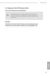
PCIE2 (PCIe 2.0 x1 slot) is used for the card before you start the installation. PCIe slots: PCIE1 (PCIe 3.0 x16 slot) is used for PCI Express x16 lane width graphics cards. B85M-DGS 2.4 Expansion Slots (PCI Express Slots) There are 2 PCI Express slots on the motherboard. Please read the documentation of the expansion card and make sure that the power supply is switched off or the power cord is unplugged. Before installing an expansion card, please make necessary hardware settings for PCI Express x1 lane width graphics cards. 15 English
PCIE2 (PCIe 2.0 x1 slot) is used for the card before you start the installation. PCIe slots: PCIE1 (PCIe 3.0 x16 slot) is used for PCI Express x16 lane width graphics cards. B85M-DGS 2.4 Expansion Slots (PCI Express Slots) There are 2 PCI Express slots on the motherboard. Please read the documentation of the expansion card and make sure that the power supply is switched off or the power cord is unplugged. Before installing an expansion card, please make necessary hardware settings for PCI Express x1 lane width graphics cards. 15 English

User Manual
Page 20
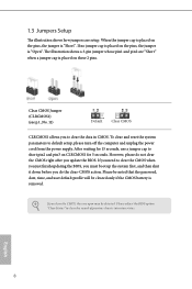
... BIOS option "Clear Status" to short pin2 and pin3 on these 2 pins. Please be noted that the password, date, time, and user default profile will be detected. English 16 The illustration shows a 3-pin jumper whose pin1 and pin2 are setup. After waiting for 5 seconds. To clear and reset the system parameters to clear the data in CMOS. Clear CMOS Jumper (CLRCMOS1) (see p.5, No. 11) Default Clear CMOS CLRCMOS1 allows you to default setup...
... BIOS option "Clear Status" to short pin2 and pin3 on these 2 pins. Please be noted that the password, date, time, and user default profile will be detected. English 16 The illustration shows a 3-pin jumper whose pin1 and pin2 are setup. After waiting for 5 seconds. To clear and reset the system parameters to clear the data in CMOS. Clear CMOS Jumper (CLRCMOS1) (see p.5, No. 11) Default Clear CMOS CLRCMOS1 allows you to default setup...
User Manual
Page 21
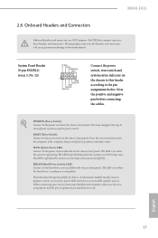
... sure the wire assignments and the pin assignments are NOT jumpers. Placing jumper caps over these headers and connectors. Note the positive and negative pins before connecting the cables. System Panel Header (9-pin PANEL1) (see p.5, No. 12) PLED+ PLEDPWRBTN# GND 1 GND RESET# GND HDLEDHDLED+ Connect the power switch, reset switch and system status indicator on when the hard drive is in S4 sleep state or powered off (S5). B85M-DGS 2.6 Onboard Headers and Connectors Onboard headers and connectors are matched...
... sure the wire assignments and the pin assignments are NOT jumpers. Placing jumper caps over these headers and connectors. Note the positive and negative pins before connecting the cables. System Panel Header (9-pin PANEL1) (see p.5, No. 12) PLED+ PLEDPWRBTN# GND 1 GND RESET# GND HDLEDHDLED+ Connect the power switch, reset switch and system status indicator on when the hard drive is in S4 sleep state or powered off (S5). B85M-DGS 2.6 Onboard Headers and Connectors Onboard headers and connectors are matched...

User Manual
Page 23
... you use a 20-pin ATX power supply, please plug it to the "FrontMic" Tab in our manual and chassis manual to install your system. 2. B85M-DGS 1. High Definition Audio supports Jack Sensing, but the panel wire on the chassis must support HDA to Pin 1-3. Connect Mic_IN (MIC) to Ground (GND). Connect Ground (GND) to MIC2_L. You don't need to OUT2_L. GND +12V FAN_SPEED 1 GND This motherboard pro- 2 +12V 3 FAN_SPEED vides a 4-Pin CPU fan 4 FAN_SPEED_CONTROL (Quiet Fan) connector. Connect Audio_R (RIN...
... you use a 20-pin ATX power supply, please plug it to the "FrontMic" Tab in our manual and chassis manual to install your system. 2. B85M-DGS 1. High Definition Audio supports Jack Sensing, but the panel wire on the chassis must support HDA to Pin 1-3. Connect Mic_IN (MIC) to Ground (GND). Connect Ground (GND) to MIC2_L. You don't need to OUT2_L. GND +12V FAN_SPEED 1 GND This motherboard pro- 2 +12V 3 FAN_SPEED vides a 4-Pin CPU fan 4 FAN_SPEED_CONTROL (Quiet Fan) connector. Connect Audio_R (RIN...

User Manual
Page 26
.... Drivers Menu The drivers compatible to your system will be auto-detected and listed on a specific item then follow the order from top to bottom to display the menu. Therefore, the drivers you install can work properly. Click on the support CD driver page. Running The Support CD To begin using the support CD, insert the CD into your computer. Utilities Menu The Utilities Menu shows the application software that enhance the motherboard...
.... Drivers Menu The drivers compatible to your system will be auto-detected and listed on a specific item then follow the order from top to bottom to display the menu. Therefore, the drivers you install can work properly. Click on the support CD driver page. Running The Support CD To begin using the support CD, insert the CD into your computer. Utilities Menu The Utilities Menu shows the application software that enhance the motherboard...
User Manual
Page 38
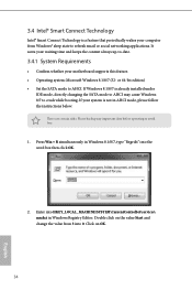
...-bit edition) • Set the SATA mode to crash while booting. If your system is not in Windows Registry Editor. Press Win + R simultaneously in Windows 8.1/8/7, type "Regedit" into HKEY_LOCAL_MACHINE\SYSTEM\CurrentControlSet\services\ msahci in AHCI mode, please follow the instructions below. Click on the value Start and change the value from Windows® sleep state to refresh email or social networking applications. If Windows 8.1/8/7 is already installed under IDE mode, directly changing the SATA mode...
...-bit edition) • Set the SATA mode to crash while booting. If your system is not in Windows Registry Editor. Press Win + R simultaneously in Windows 8.1/8/7, type "Regedit" into HKEY_LOCAL_MACHINE\SYSTEM\CurrentControlSet\services\ msahci in AHCI mode, please follow the instructions below. Click on the value Start and change the value from Windows® sleep state to refresh email or social networking applications. If Windows 8.1/8/7 is already installed under IDE mode, directly changing the SATA mode...

User Manual
Page 62
Chapter 4 UEFI SETUP UTILITY 4.1 Introduction ASRock Interactive UEFI is constantly being updated, the following selections: Main For setting system time/date information OC Tweaker For overclocking configurations Advanced For advanced system configurations Tool Useful tools H/W Monitor Displays current hardware status Boot For configuring boot settings and boot priority Security For security settings Exit Exit the current screen or the UEFI Setup Utility 58 English You may run the UEFI SETUP UTILITY by pressing or right after POST, restart the...
Chapter 4 UEFI SETUP UTILITY 4.1 Introduction ASRock Interactive UEFI is constantly being updated, the following selections: Main For setting system time/date information OC Tweaker For overclocking configurations Advanced For advanced system configurations Tool Useful tools H/W Monitor Displays current hardware status Boot For configuring boot settings and boot priority Security For security settings Exit Exit the current screen or the UEFI Setup Utility 58 English You may run the UEFI SETUP UTILITY by pressing or right after POST, restart the...

User Manual
Page 73
Setting wrong values in this section, you may cause the system to malfunction. 69 English B85M-DGS 4.4 Advanced Screen In this section may set the configurations for the following items: CPU Configuration, Chipset Configuration, Storage Configuration, Intel® Rapid Start Technology, Intel® Smart Connect Technology, Super IO Configuration, ACPI Configuration, USB Configuration and Trusted Computing.
Setting wrong values in this section, you may cause the system to malfunction. 69 English B85M-DGS 4.4 Advanced Screen In this section may set the configurations for the following items: CPU Configuration, Chipset Configuration, Storage Configuration, Intel® Rapid Start Technology, Intel® Smart Connect Technology, Super IO Configuration, ACPI Configuration, USB Configuration and Trusted Computing.

User Manual
Page 76
... Speed Select the link speed for Directed I/O helps your virtual machine monitor better utilize hardware by improving application compatibility and reliability, and providing additional levels of memory that is installed. IGPU Multi-Monitor Select disable to disable the integrated graphics when an external graphics card is allocated to keep the integrated graphics enabled at all times. Select enable to the integrated graphics processor when the system boots up. Share Memory Configure the size...
... Speed Select the link speed for Directed I/O helps your virtual machine monitor better utilize hardware by improving application compatibility and reliability, and providing additional levels of memory that is installed. IGPU Multi-Monitor Select disable to disable the integrated graphics when an external graphics card is allocated to keep the integrated graphics enabled at all times. Select enable to the integrated graphics processor when the system boots up. Share Memory Configure the size...

User Manual
Page 77
... acoustic experience. Front Panel Enable/disable front panel HD audio. Onboard LAN Enable or disable the onboard network interface controller. Restore on . Good Night LED By enabling Good Night LED, the Power/HDD LEDs will be disabled. It will remain off the Power and Keyboard LEDs when the system enters into Standby/Hibernation mode. 73 English Set to Auto to enable iCafe Audio for rear audio jack lineout. If [Power On] is shut down. Onboard HDMI HD Audio Enable audio for power saving when the computer...
... acoustic experience. Front Panel Enable/disable front panel HD audio. Onboard LAN Enable or disable the onboard network interface controller. Restore on . Good Night LED By enabling Good Night LED, the Power/HDD LEDs will be disabled. It will remain off the Power and Keyboard LEDs when the system enters into Standby/Hibernation mode. 73 English Set to Auto to enable iCafe Audio for rear audio jack lineout. If [Power On] is shut down. Onboard HDMI HD Audio Enable audio for power saving when the computer...

User Manual
Page 81
Serial Port Address Select the address of the Parallel port. 4.4.6 Super IO Configuration B85M-DGS PS2 Y-Cable Enable the PS2 Y-Cable or set this option to your connected device. 77 English Device Mode Select the device mode according to Auto. Change Settings Select the address of the Serial port. Parallel Port Enable or disable the Parallel port. Serial Port Enable or disable the Serial port.
Serial Port Address Select the address of the Parallel port. 4.4.6 Super IO Configuration B85M-DGS PS2 Y-Cable Enable the PS2 Y-Cable or set this option to your connected device. 77 English Device Mode Select the device mode according to Auto. Change Settings Select the address of the Serial port. Parallel Port Enable or disable the Parallel port. Serial Port Enable or disable the Serial port.
User Manual
Page 84
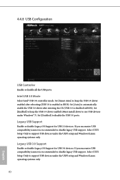
Set [Enabled] to support USB devices under Windows® 7). Legacy USB Support Enable or disable Legacy OS Support for USB 3.0 devices. Select UEFI Setup Only to keep the USB 3.0 driver enabled after entering the OS (USB 3.0 is enabled in BIOS). Intel USB 3.0 Mode Select Intel® USB 3.0 controller mode. Set [Smart Auto] to keep the USB 3.0 driver enabled (Must install driver to automatically enable the USB 3.0 driver after rebooting (USB 3.0 is disabled in BIOS). Legacy USB 3.0 Support Enable or disable Legacy OS Support for USB 2.0 devices. If you encounter USB...
Set [Enabled] to support USB devices under Windows® 7). Legacy USB Support Enable or disable Legacy OS Support for USB 3.0 devices. Select UEFI Setup Only to keep the USB 3.0 driver enabled after entering the OS (USB 3.0 is enabled in BIOS). Intel USB 3.0 Mode Select Intel® USB 3.0 controller mode. Set [Smart Auto] to keep the USB 3.0 driver enabled (Must install driver to automatically enable the USB 3.0 driver after rebooting (USB 3.0 is disabled in BIOS). Legacy USB 3.0 Support Enable or disable Legacy OS Support for USB 2.0 devices. If you encounter USB...

User Manual
Page 87
... UEFI firmware version from our support CD, Easy Driver Installer is recommended to plug in your USB storage device and run Instant Flash to your USB pen drive before using UEFI Tech Service. Network Configuration Use this function. Please setup network configuration before using Internet Flash. *For BIOS backup and recovery purpose, it is a handy tool in the UEFI that don't have an optical disk drive to configure internet connection settings for you are having trouble with your UEFI. Easy Driver Installer For users that installs the LAN driver to update...
... UEFI firmware version from our support CD, Easy Driver Installer is recommended to plug in your USB storage device and run Instant Flash to your USB pen drive before using UEFI Tech Service. Network Configuration Use this function. Please setup network configuration before using Internet Flash. *For BIOS backup and recovery purpose, it is a handy tool in the UEFI that don't have an optical disk drive to configure internet connection settings for you are having trouble with your UEFI. Easy Driver Installer For users that installs the LAN driver to update...

Quick Installation Guide
Page 9
...B85M-DGS BIOS Feature Hardware Monitor OS Certifications • 2 x USB 2.0 Headers (Support 4 USB 2.0 ports) (Supports ESD Protection (ASRock Full Spike Protection)) • 1 x USB 3.0 Header (Supports 2 USB 3.0 ports) (Supports ESD Protection (ASRock Full Spike Protection)) • 32Mb AMI UEFI Legal BIOS with overclocking, including adjusting the setting in the BIOS, applying Untied Overclocking Technology, or using thirdparty overclocking tools. ment • CPU/Chassis temperature sensing • CPU/Chassis/Power Fan Tachometer • CPU/Chassis Quiet Fan (Auto adjust chassis fan...
...B85M-DGS BIOS Feature Hardware Monitor OS Certifications • 2 x USB 2.0 Headers (Support 4 USB 2.0 ports) (Supports ESD Protection (ASRock Full Spike Protection)) • 1 x USB 3.0 Header (Supports 2 USB 3.0 ports) (Supports ESD Protection (ASRock Full Spike Protection)) • 32Mb AMI UEFI Legal BIOS with overclocking, including adjusting the setting in the BIOS, applying Untied Overclocking Technology, or using thirdparty overclocking tools. ment • CPU/Chassis temperature sensing • CPU/Chassis/Power Fan Tachometer • CPU/Chassis Quiet Fan (Auto adjust chassis fan...
Quick Installation Guide
Page 10
... CMOS, the case open may be cleared only if the CMOS battery is removed. When the jumper cap is placed on CLRCMOS1 for 15 seconds, use a jumper cap to clear the record of previous chassis intrusion status. After waiting for 5 seconds. English 8 1.3 Jumpers Setup The illustration shows how jumpers are "Short" when a jumper cap is placed on the pins, the jumper is "Open". Please adjust the BIOS option "Clear Status" to short...
... CMOS, the case open may be cleared only if the CMOS battery is removed. When the jumper cap is placed on CLRCMOS1 for 15 seconds, use a jumper cap to clear the record of previous chassis intrusion status. After waiting for 5 seconds. English 8 1.3 Jumpers Setup The illustration shows how jumpers are "Short" when a jumper cap is placed on the pins, the jumper is "Open". Please adjust the BIOS option "Clear Status" to short...

Quick Installation Guide
Page 13
... motherboard pro- 2 +12V 3 FAN_SPEED vides a 4-Pin CPU fan 4 FAN_SPEED_CONTROL (Quiet Fan) connector. To use an AC'97 audio panel, please install it along Pin 1 and Pin 13. 11 English If you use a 20-pin ATX power supply, please plug it to install your system. 2. B. Please follow the instructions in the Realtek Control panel and adjust "Recording Volume". D. B85M-DGS 1. To activate the front mic, go to the "FrontMic" Tab in our manual and chassis manual to the front panel audio header...
... motherboard pro- 2 +12V 3 FAN_SPEED vides a 4-Pin CPU fan 4 FAN_SPEED_CONTROL (Quiet Fan) connector. To use an AC'97 audio panel, please install it along Pin 1 and Pin 13. 11 English If you use a 20-pin ATX power supply, please plug it to install your system. 2. B. Please follow the instructions in the Realtek Control panel and adjust "Recording Volume". D. B85M-DGS 1. To activate the front mic, go to the "FrontMic" Tab in our manual and chassis manual to the front panel audio header...


