User Manual
Page 5
... Storage Configuration to change without further notice. Because the motherboard specifications and the BIOS software might be updated, the content of this manual will be subject to AHCI mode. To get better performance in Windows® 7 / 7 64-bit / VistaTM / VistaTM 64bit, it is recommended to set the BIOS option in , 24.4 cm x 21.3 cm) ASRock B75M-GL R2.0 Quick Installation Guide ASRock B75M-GL R2.0 Support CD 2 x Serial ATA (SATA) Data Cables (Optional) 1 x I/O Panel Shield ASRock Reminds You... Chapter 1: Introduction Thank you are using...
... Storage Configuration to change without further notice. Because the motherboard specifications and the BIOS software might be updated, the content of this manual will be subject to AHCI mode. To get better performance in Windows® 7 / 7 64-bit / VistaTM / VistaTM 64bit, it is recommended to set the BIOS option in , 24.4 cm x 21.3 cm) ASRock B75M-GL R2.0 Quick Installation Guide ASRock B75M-GL R2.0 Support CD 2 x Serial ATA (SATA) Data Cables (Optional) 1 x I/O Panel Shield ASRock Reminds You... Chapter 1: Introduction Thank you are using...

User Manual
Page 10
... new BIOS file to your USB flash drive, floppy disk or hard drive, then you can press the key during the POST or the key to enter into the BIOS setup menu to access ASRock Instant Flash. Please visit our website for internet browsers, is IE8. This convenient BIOS update tool allows you can load the OC profile to their own system to update system BIOS without sacrificing computing performance. With APP Charger driver installed, you...
... new BIOS file to your USB flash drive, floppy disk or hard drive, then you can press the key during the POST or the key to enter into the BIOS setup menu to access ASRock Instant Flash. Please visit our website for internet browsers, is IE8. This convenient BIOS update tool allows you can load the OC profile to their own system to update system BIOS without sacrificing computing performance. With APP Charger driver installed, you...

User Manual
Page 13
...Power Connector (ATX12V1) 18 System Panel Header (PANEL1, Black) 3 1155-Pin CPU Socket 19 USB 2.0 Header (USB6_7, Black) 4 CPU Fan Connector (CPU_FAN1) 20 USB 2.0 Header (USB8_9, Black) 5 2 x 240-pin DDR3 DIMM Slots 21 Consumer Infrared Module Header (DDR3_A1, DDR3_B1, Black) (CIR1, Gray) 6 ATX Power Connector (ATXPWR1) 22 Infrared Module Header (IR1) 7 SATA3 Connector (SATA3_0, Gray) 23 COM Port Header (COM1) 8 Chassis Fan Connector (CHA_FAN1) 24 Print Port Header (LPT1) 9 USB 3.0 Header (USB3_2_3, Black) 25 Chassis Intrusion Header (CI1) 10 Intel B75 Chipset 26 PCI Express...
...Power Connector (ATX12V1) 18 System Panel Header (PANEL1, Black) 3 1155-Pin CPU Socket 19 USB 2.0 Header (USB6_7, Black) 4 CPU Fan Connector (CPU_FAN1) 20 USB 2.0 Header (USB8_9, Black) 5 2 x 240-pin DDR3 DIMM Slots 21 Consumer Infrared Module Header (DDR3_A1, DDR3_B1, Black) (CIR1, Gray) 6 ATX Power Connector (ATXPWR1) 22 Infrared Module Header (IR1) 7 SATA3 Connector (SATA3_0, Gray) 23 COM Port Header (COM1) 8 Chassis Fan Connector (CHA_FAN1) 24 Print Port Header (LPT1) 9 USB 3.0 Header (USB3_2_3, Black) 25 Chassis Intrusion Header (CI1) 10 Intel B75 Chipset 26 PCI Express...

User Manual
Page 23
... AMD driver updates. Select "2 GPUs" and click "Apply". 23 Remove the AMD drivers if you have Windows® XP Service Pack 2 or higher installed in your Windows® taskbar. We recommend using this utility to your system, and restart your computer and boot into OS. For Windows® 7 / VistaTM OS: Install the CATALYST Control Center. Install the VGA card drivers to uninstall any VGA drivers installed in your system, there is an optional download. Step 2. Power...
... AMD driver updates. Select "2 GPUs" and click "Apply". 23 Remove the AMD drivers if you have Windows® XP Service Pack 2 or higher installed in your Windows® taskbar. We recommend using this utility to your system, and restart your computer and boot into OS. For Windows® 7 / VistaTM OS: Install the CATALYST Control Center. Install the VGA card drivers to uninstall any VGA drivers installed in your system, there is an optional download. Step 2. Power...

User Manual
Page 25
... I /O panel, and connect D-Sub monitor cable to D-Sub port on VGA card to your system and restart your system boots. Connect DVI-D monitor cable to support dual VGA output so that DVI-D and D-sub can easily enjoy the benefits of dual monitor function after your computer. 25 2.8 Dual Monitor and Surround Display Features Dual Monitor Feature This motherboard supports dual monitor feature. To enable dual monitor feature, please follow the below steps: 1. D-Sub port DVI-D port 2. This motherboard also provides independent display controllers...
... I /O panel, and connect D-Sub monitor cable to D-Sub port on VGA card to your system and restart your system boots. Connect DVI-D monitor cable to support dual VGA output so that DVI-D and D-sub can easily enjoy the benefits of dual monitor function after your computer. 25 2.8 Dual Monitor and Surround Display Features Dual Monitor Feature This motherboard supports dual monitor feature. To enable dual monitor feature, please follow the below steps: 1. D-Sub port DVI-D port 2. This motherboard also provides independent display controllers...

User Manual
Page 40
...-bit. B. Enter UEFI SETUP UTILITY Advanced screen Storage Configuration. A. STEP 2: Install Windows® XP / XP 64-bit OS on the support CD driver page. Using SATA / SATA2 / SATA3 HDDs without NCQ function STEP 1: Set Up UEFI. Set the option "SATA Mode Selection" to install those required drivers. Then, the drivers compatible to your system can work properly. 2.16 Installing Windows® 7 / 7 64-bit / VistaTM / VistaTM 64-bit / XP / XP 64-bit Without RAID Functions If you want to your optical drive first. 2.15 Driver Installation Guide To install...
...-bit. B. Enter UEFI SETUP UTILITY Advanced screen Storage Configuration. A. STEP 2: Install Windows® XP / XP 64-bit OS on the support CD driver page. Using SATA / SATA2 / SATA3 HDDs without NCQ function STEP 1: Set Up UEFI. Set the option "SATA Mode Selection" to install those required drivers. Then, the drivers compatible to your system can work properly. 2.16 Installing Windows® 7 / 7 64-bit / VistaTM / VistaTM 64-bit / XP / XP 64-bit Without RAID Functions If you want to your optical drive first. 2.15 Driver Installation Guide To install...

User Manual
Page 50
...; Windows® XP / VistaTM / 7 is [All]. CPU C6 State Support Use this to enable or disable CPU C3 (ACPI C2) report to keep the CPU from the chipset. Set to enable in each processor package. This option will program into C State package limit register. CPU Thermal Throttling You may select [Enabled] to enable CPU internal thermal control mechanism to OS. No-Execute Memory Protection No-Execution (NX) Memory Protection Technology is [Auto]. Active Processor Cores Use this...
...; Windows® XP / VistaTM / 7 is [All]. CPU C6 State Support Use this to enable or disable CPU C3 (ACPI C2) report to keep the CPU from the chipset. Set to enable in each processor package. This option will program into C State package limit register. CPU Thermal Throttling You may select [Enabled] to enable CPU internal thermal control mechanism to OS. No-Execute Memory Protection No-Execution (NX) Memory Protection Technology is [Auto]. Active Processor Cores Use this...

User Manual
Page 52
...(R) Virtualization Technology for Directed I/O. If you to set onboard VGA share memory feature. PCIE1 Link Speed This allows you to enable or disable IGPU Multi-Monitor. The default value is [Disabled]. The default value is [Auto]. The default value is [Auto]. IGPU Multi-Monitor This allows you to select PCIE1 Link Speed. The default value is [Enabled]. The default value is [Enabled]. 52 The default value is [PCI Express]. Render Standby Use this option. 3.4.2 North Bridge Configuration Primary Graphics...
...(R) Virtualization Technology for Directed I/O. If you to set onboard VGA share memory feature. PCIE1 Link Speed This allows you to enable or disable IGPU Multi-Monitor. The default value is [Disabled]. The default value is [Auto]. The default value is [Auto]. IGPU Multi-Monitor This allows you to select PCIE1 Link Speed. The default value is [Enabled]. The default value is [Enabled]. 52 The default value is [PCI Express]. Render Standby Use this option. 3.4.2 North Bridge Configuration Primary Graphics...

User Manual
Page 59
... Use this option to below descriptions for USB devices. Enables support for USB 3.0 devices. USB devices are not allowed to use of these four options: [Enabled] - The default value is [Enabled]. If you have USB compatibility issues, it is recommended to select [Disabled] to enable or disable legacy support for legacy USB. [Auto] - Legacy USB 3.0 Support Use this option to enter OS. [UEFI Setup Only] - 3.4.9 USB Configuration USB 2.0 Controller Use this item to enable or disable the use only under legacy OS and UEFI setup when [Disabled] is selected. There are connected...
... Use this option to below descriptions for USB devices. Enables support for USB 3.0 devices. USB devices are not allowed to use of these four options: [Enabled] - The default value is [Enabled]. If you have USB compatibility issues, it is recommended to select [Disabled] to enable or disable legacy support for legacy USB. [Auto] - Legacy USB 3.0 Support Use this option to enter OS. [UEFI Setup Only] - 3.4.9 USB Configuration USB 2.0 Controller Use this item to enable or disable the use only under legacy OS and UEFI setup when [Disabled] is selected. There are connected...

User Manual
Page 66
... CD-ROM drive. Click on the file "ASRSETUP.EXE" in this chapter for more about ASRock, welcome to display the menu. 4.2.2 Drivers Menu The Drivers Menu shows the available device's drivers if the system detects installed devices. Because motherboard settings and hardware options vary, use the setup procedures in the Support CD to visit ASRock's website at http://www.asrock.com; If the Main Menu does not appear automatically, locate and double click on a specific item...
... CD-ROM drive. Click on the file "ASRSETUP.EXE" in this chapter for more about ASRock, welcome to display the menu. 4.2.2 Drivers Menu The Drivers Menu shows the available device's drivers if the system detects installed devices. Because motherboard settings and hardware options vary, use the setup procedures in the Support CD to visit ASRock's website at http://www.asrock.com; If the Main Menu does not appear automatically, locate and double click on a specific item...

Quick Installation Guide
Page 2
..., Black) 25 Chassis Intrusion Header (CI1) 10 Intel B75 Chipset 26 PCI Express 2.0 x16 Slot (PCIE2, Black) 11 SPI Flash Memory (64Mb) 27 PCI Slot (PCI2, Black) 12 SATA2 Connector (SATA2_1, Black) 28 PCI Slot (PCI1, Black) 13 SATA2 Connector (SATA2_3, Black) 29 PCI Express 3.0 x16 Slot (PCIE1, Black) 14 SATA2 Connector (SATA2_4, Black) 30 Front Panel Audio Header 15 Chassis Speaker Header (SPEAKER1, Black) (HD_AUDIO1, Black) 16 SATA2 Connector (SATA2_5, Black) 31 Clear CMOS Jumper (CLRCMOS1) English 2 ASRock B75M-GL R2.0 Motherboard
..., Black) 25 Chassis Intrusion Header (CI1) 10 Intel B75 Chipset 26 PCI Express 2.0 x16 Slot (PCIE2, Black) 11 SPI Flash Memory (64Mb) 27 PCI Slot (PCI2, Black) 12 SATA2 Connector (SATA2_1, Black) 28 PCI Slot (PCI1, Black) 13 SATA2 Connector (SATA2_3, Black) 29 PCI Express 3.0 x16 Slot (PCIE1, Black) 14 SATA2 Connector (SATA2_4, Black) 30 Front Panel Audio Header 15 Chassis Speaker Header (SPEAKER1, Black) (HD_AUDIO1, Black) 16 SATA2 Connector (SATA2_5, Black) 31 Clear CMOS Jumper (CLRCMOS1) English 2 ASRock B75M-GL R2.0 Motherboard

Quick Installation Guide
Page 4
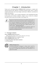
... Windows® 7 / 7 64-bit / VistaTM / VistaTM 64bit, it is recommended to set the BIOS option in Storage Configuration to this manual will be subject to the "User Manual" in , 24.4 cm x 21.3 cm) ASRock B75M-GL R2.0 Quick Installation Guide ASRock B75M-GL R2.0 Support CD 2 x Serial ATA (SATA) Data Cables (Optional) 1 x I/O Panel Shield ASRock Reminds You... More detailed information of the motherboard and step-bystep installation guide. ASRock website http://www.asrock.com If you are using. Because the motherboard...
... Windows® 7 / 7 64-bit / VistaTM / VistaTM 64bit, it is recommended to set the BIOS option in Storage Configuration to this manual will be subject to the "User Manual" in , 24.4 cm x 21.3 cm) ASRock B75M-GL R2.0 Quick Installation Guide ASRock B75M-GL R2.0 Support CD 2 x Serial ATA (SATA) Data Cables (Optional) 1 x I/O Panel Shield ASRock Reminds You... More detailed information of the motherboard and step-bystep installation guide. ASRock website http://www.asrock.com If you are using. Because the motherboard...

Quick Installation Guide
Page 5
...; Turbo Boost 2.0 Technology - Supports Intel® Rapid Start Technology and Smart Connect Technology - Pixel Shader 4.1, DirectX 10.1 with DVI port 5 ASRock B75M-GL R2.0 Motherboard English Supports HDCP function with Intel® Sandy Bridge CPU - With Intel® Sandy Bridge CPU, it only supports PCIE 2.0. - 1 x PCI Express 2.0 x16 slot (PCIE2: x4 mode) - 2 x PCI slots - resolution up to 2048x1536 @ 75Hz - Dual Channel DDR3 Memory Technology (see CAUTION 1) - Supports Intel® HD Graphics Built-in , 24.4 cm x 21.3 cm - Supports DVI with Intel...
...; Turbo Boost 2.0 Technology - Supports Intel® Rapid Start Technology and Smart Connect Technology - Pixel Shader 4.1, DirectX 10.1 with DVI port 5 ASRock B75M-GL R2.0 Motherboard English Supports HDCP function with Intel® Sandy Bridge CPU - With Intel® Sandy Bridge CPU, it only supports PCIE 2.0. - 1 x PCI Express 2.0 x16 slot (PCIE2: x4 mode) - 2 x PCI slots - resolution up to 2048x1536 @ 75Hz - Dual Channel DDR3 Memory Technology (see CAUTION 1) - Supports Intel® HD Graphics Built-in , 24.4 cm x 21.3 cm - Supports DVI with Intel...
Quick Installation Guide
Page 9
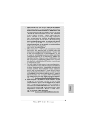
... the POST or the key to enter into the BIOS setup menu to improve efficiency when the CPU cores are idle without preparing an additional floppy diskette or other complicated flash utility. In Hardware Monitor, it shows the fan speed and temperature for IE that the USB flash drive or hard drive must use ASRock SmartView feature, please make sure your OS version is the smart start...
... the POST or the key to enter into the BIOS setup menu to improve efficiency when the CPU cores are idle without preparing an additional floppy diskette or other complicated flash utility. In Hardware Monitor, it shows the fan speed and temperature for IE that the USB flash drive or hard drive must use ASRock SmartView feature, please make sure your OS version is the smart start...

Quick Installation Guide
Page 10
... 775 and 1156 CPU Fan can boost USB storage device performance. ASRock XFast RAM shortens the loading time of internet access granted to be noticed that is detected, the system will automatically finish the BIOS update procedure after entering S4/S5 state. 18. Please be placed in order to dehumidify the system after regaining power. ASRock XFast USB can be used . 10 ASRock B75M-GL R2.0 Motherboard English Traffi...
... 775 and 1156 CPU Fan can boost USB storage device performance. ASRock XFast RAM shortens the loading time of internet access granted to be noticed that is detected, the system will automatically finish the BIOS update procedure after entering S4/S5 state. 18. Please be placed in order to dehumidify the system after regaining power. ASRock XFast USB can be used . 10 ASRock B75M-GL R2.0 Motherboard English Traffi...

Quick Installation Guide
Page 17
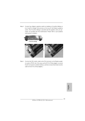
... motherboard's chassis fan connector (CHA_FAN1) when using multiple graphics cards for later use . Step 6. Only PCIE1 slot supports Gen 3 speed. Step 3. 2.6 Expansion Slots (PCI and PCI Express Slots) There are used to install expansion cards that the power supply is switched off or the power cord is unplugged. Therefore, PCIE1 will run the PCI Express in a chassis). Step 2. PCIE slots:PCIE1 (PCIE 3.0 x16 slot) is used for the card before you start the installation. In CrossFireXTM mode, please install the PCI Express x16 graphics cards on PCIE1 slot. 2. Step 5. Fasten the card...
... motherboard's chassis fan connector (CHA_FAN1) when using multiple graphics cards for later use . Step 6. Only PCIE1 slot supports Gen 3 speed. Step 3. 2.6 Expansion Slots (PCI and PCI Express Slots) There are used to install expansion cards that the power supply is switched off or the power cord is unplugged. Therefore, PCIE1 will run the PCI Express in a chassis). Step 2. PCIE slots:PCIE1 (PCIE 3.0 x16 slot) is used for the card before you start the installation. In CrossFireXTM mode, please install the PCI Express x16 graphics cards on PCIE1 slot. 2. Step 5. Fasten the card...
Quick Installation Guide
Page 19
... motherboard. Step 2. Connect two Radeon graphics cards by installing a CrossFire Bridge on the CrossFire Bridge Interconnects on PCIE1 slot. (You may use the DVI to D-Sub adapter to convert the DVI connector to D-Sub interface, and then connect the D-Sub monitor cable to the DVI to your graphics card vendor for details.) CrossFire Bridge or Step 3. Please refer to D-Sub adapter.) English 19 ASRock B75M-GL R2.0 Motherboard...
... motherboard. Step 2. Connect two Radeon graphics cards by installing a CrossFire Bridge on the CrossFire Bridge Interconnects on PCIE1 slot. (You may use the DVI to D-Sub adapter to convert the DVI connector to D-Sub interface, and then connect the D-Sub monitor cable to the DVI to your graphics card vendor for details.) CrossFire Bridge or Step 3. Please refer to D-Sub adapter.) English 19 ASRock B75M-GL R2.0 Motherboard...

Quick Installation Guide
Page 20
... for AMD driver updates. Please check AMD's website for details. You will find "AMD Catalyst Control Center" on your computer. We recommend using this utility to be installed (If you have Microsoft .NET Framework installed prior to downloading and installing the CATALYST Control Center. AMD recommends Windows® XP Service Pack 2 or higher to uninstall any VGA drivers installed in your system, there is an optional download. English 20 ASRock B75M-GL R2.0 Motherboard Step...
... for AMD driver updates. Please check AMD's website for details. You will find "AMD Catalyst Control Center" on your computer. We recommend using this utility to be installed (If you have Microsoft .NET Framework installed prior to downloading and installing the CATALYST Control Center. AMD recommends Windows® XP Service Pack 2 or higher to uninstall any VGA drivers installed in your system, there is an optional download. English 20 ASRock B75M-GL R2.0 Motherboard Step...

Quick Installation Guide
Page 22
... internal VGA output support (DVI-D and D-Sub), you can freely enjoy the benefits of dual monitor feature without installing any add-on the I /O panel, and connect D-Sub monitor cable to D-Sub port on VGA card to this motherboard. 2.8 Dual Monitor and Surround Display Features Dual Monitor Feature This motherboard supports dual monitor feature. This motherboard also provides independent display controllers for DVI-D and D-Sub to your computer. 22 ASRock B75M-GL R2.0 Motherboard English If you have installed onboard VGA driver from our support...
... internal VGA output support (DVI-D and D-Sub), you can freely enjoy the benefits of dual monitor feature without installing any add-on the I /O panel, and connect D-Sub monitor cable to D-Sub port on VGA card to this motherboard. 2.8 Dual Monitor and Surround Display Features Dual Monitor Feature This motherboard supports dual monitor feature. This motherboard also provides independent display controllers for DVI-D and D-Sub to your computer. 22 ASRock B75M-GL R2.0 Motherboard English If you have installed onboard VGA driver from our support...

Quick Installation Guide
Page 32
... install Windows® XP / XP 64-bit OS on the support CD driver page. AHCI mode is not supported under Windows® XP / XP 64-bit. Therefore, the drivers you install can be auto-detected and listed on your SATA / SATA2 / SATA3 HDDs without RAID functions, please follow the order from top to bottom to this connector. Chassis Intrusion Header (2-pin CI1) (see p.2, No. 23) Please connect an ATX 12V power supply to install those required drivers...
... install Windows® XP / XP 64-bit OS on the support CD driver page. AHCI mode is not supported under Windows® XP / XP 64-bit. Therefore, the drivers you install can be auto-detected and listed on your SATA / SATA2 / SATA3 HDDs without RAID functions, please follow the order from top to bottom to this connector. Chassis Intrusion Header (2-pin CI1) (see p.2, No. 23) Please connect an ATX 12V power supply to install those required drivers...


