
User Manual
Page 2
Products and corporate names appearing in this motherboard contains Perchlorate, a toxic substance controlled in Perchlorate Best Management Practices (BMP) regulations passed by ASRock. In no responsibility for any errors or omissions that may be reproduced, transcribed, transmitted, or translated ...USA ONLY The Lithium battery adopted on this documentation may or may apply, see www.dtsc.ca.gov/hazardouswaste/ perchlorate" ASRock Website: http://www.asrock.com When you discard the Lithium battery in California, USA, please follow the related regulations in the documentation or product....
Products and corporate names appearing in this motherboard contains Perchlorate, a toxic substance controlled in Perchlorate Best Management Practices (BMP) regulations passed by ASRock. In no responsibility for any errors or omissions that may be reproduced, transcribed, transmitted, or translated ...USA ONLY The Lithium battery adopted on this documentation may or may apply, see www.dtsc.ca.gov/hazardouswaste/ perchlorate" ASRock Website: http://www.asrock.com When you discard the Lithium battery in California, USA, please follow the related regulations in the documentation or product....
User Manual
Page 4
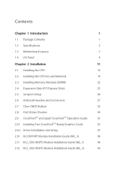
Contents Chapter 1 Introduction 1 1.1 Package Contents 1 1.2 Specifications 2 1.3 Motherboard Layout 7 1.4 I/O Panel 9 Chapter 2 Installation 11 2.1 Installing the CPU 12 2.2 Installing the CPU Fan and Heatsink 14 2.3 Installing Memory Modules (DIMM) 22 2.4 Expansion Slots (PCI Express ...
Contents Chapter 1 Introduction 1 1.1 Package Contents 1 1.2 Specifications 2 1.3 Motherboard Layout 7 1.4 I/O Panel 9 Chapter 2 Installation 11 2.1 Installing the CPU 12 2.2 Installing the CPU Fan and Heatsink 14 2.3 Installing Memory Modules (DIMM) 22 2.4 Expansion Slots (PCI Express ...
User Manual
Page 5
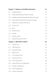
Chapter 3 Software and Utilities Operation 46 3.1 Installing Drivers 46 3.2 ASRock Motherboard Utility (A-Tuning) 47 3.2.1 Installing ASRock Motherboard Utility (A-Tuning) 47 3.2.2 Using ASRock Motherboard Utility (A-Tuning) 47 3.3 ASRock Live Update & APP Shop 50 3.3.1 UI Overview 50 3.3.2 Apps 51 3.3.3 BIOS & Drivers 54 3.3.4 Setting 55 3.4 Nahimic Audio 56 3.5 ASRock Polychrome SYNC 57 Chapter 4 UEFI SETUP UTILITY 60 4.1 Introduction 60 4.1.1 UEFI Menu Bar...
Chapter 3 Software and Utilities Operation 46 3.1 Installing Drivers 46 3.2 ASRock Motherboard Utility (A-Tuning) 47 3.2.1 Installing ASRock Motherboard Utility (A-Tuning) 47 3.2.2 Using ASRock Motherboard Utility (A-Tuning) 47 3.3 ASRock Live Update & APP Shop 50 3.3.1 UI Overview 50 3.3.2 Apps 51 3.3.3 BIOS & Drivers 54 3.3.4 Setting 55 3.4 Nahimic Audio 56 3.5 ASRock Polychrome SYNC 57 Chapter 4 UEFI SETUP UTILITY 60 4.1 Introduction 60 4.1.1 UEFI Menu Bar...
User Manual
Page 7
... you for M.2 Socket (Optional) 1 English Chapter 4 contains the configuration guide of the BIOS setup. ASRock website http://www.asrock.com. 1.1 Package Contents • ASRock B550M Steel Legend Motherboard (Micro ATX Form Factor) • ASRock B550M Steel Legend Quick Installation Guide • ASRock B550M Steel Legend Support CD • 2 x Serial ATA (SATA) Data Cables (Optional) • 2 x Screws for purchasing ASRock B550M Steel Legend motherboard, a reliable motherboard produced under ASRock's consistently stringent quality control.
... you for M.2 Socket (Optional) 1 English Chapter 4 contains the configuration guide of the BIOS setup. ASRock website http://www.asrock.com. 1.1 Package Contents • ASRock B550M Steel Legend Motherboard (Micro ATX Form Factor) • ASRock B550M Steel Legend Quick Installation Guide • ASRock B550M Steel Legend Support CD • 2 x Serial ATA (SATA) Data Cables (Optional) • 2 x Screws for purchasing ASRock B550M Steel Legend motherboard, a reliable motherboard produced under ASRock's consistently stringent quality control.

User Manual
Page 13
B550M Steel Legend 1.3 Motherboard Layout 12 34 56 31 CLRC BTN1 ATX12V1 ATX12V2 HDMI1 DP1 PS2 Keyboard/ Mouse SOCKET AM4 USB 2.0 T: USB1 B: USB2 USB 3.2 Gen2 T: USB31_TA_1 B: USB31_TC_1 USB 3.2 Gen1 T: ...
B550M Steel Legend 1.3 Motherboard Layout 12 34 56 31 CLRC BTN1 ATX12V1 ATX12V2 HDMI1 DP1 PS2 Keyboard/ Mouse SOCKET AM4 USB 2.0 T: USB1 B: USB2 USB 3.2 Gen2 T: USB31_TA_1 B: USB31_TC_1 USB 3.2 Gen1 T: ...
User Manual
Page 17
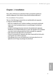
... change any components, place them on a grounded anti-static pad or in the bag that the motherboard fits into it. B550M Steel Legend Chapter 2 Installation This is a Micro ATX form factor motherboard. Failure to do so may damage the motherboard. 11 English Also remember to use a grounded wrist strap or touch a safety grounded object before you...
... change any components, place them on a grounded anti-static pad or in the bag that the motherboard fits into it. B550M Steel Legend Chapter 2 Installation This is a Micro ATX form factor motherboard. Failure to do so may damage the motherboard. 11 English Also remember to use a grounded wrist strap or touch a safety grounded object before you...

User Manual
Page 20
Please turn off the power or remove the power cord before changing a CPU or heatsink. 2.2 Installing the CPU Fan and Heatsink After you install the CPU into this motherboard, it is necessary to install a larger heatsink and cooling fan to improve heat dissipation. Installing the CPU Box Cooler SR1 1 2 14 English Make sure that the CPU and the heatsink are securely fastened and in good contact with each other. You also need to spray thermal grease between the CPU and the heatsink to dissipate heat.
Please turn off the power or remove the power cord before changing a CPU or heatsink. 2.2 Installing the CPU Fan and Heatsink After you install the CPU into this motherboard, it is necessary to install a larger heatsink and cooling fan to improve heat dissipation. Installing the CPU Box Cooler SR1 1 2 14 English Make sure that the CPU and the heatsink are securely fastened and in good contact with each other. You also need to spray thermal grease between the CPU and the heatsink to dissipate heat.

User Manual
Page 24
The headers might be in a different position on your motherboard. 18 English 4 CPU_FAN1 *The diagrams shown here are for reference only.
The headers might be in a different position on your motherboard. 18 English 4 CPU_FAN1 *The diagrams shown here are for reference only.

User Manual
Page 27
The headers might be in a different position on your motherboard. 21 English B550M Steel Legend 5 CPU_FAN1 6 CPU_FAN1 +12V RGB_LED2 *The diagrams shown here are for reference only.
The headers might be in a different position on your motherboard. 21 English B550M Steel Legend 5 CPU_FAN1 6 CPU_FAN1 +12V RGB_LED2 *The diagrams shown here are for reference only.

User Manual
Page 28
2.3 Installing Memory Modules (DIMM) This motherboard provides four 288-pin DDR4 (Double Data Rate 4) DIMM slots, and supports Dual Channel Memory Technology. 1. AMD non-XMP Memory Frequency Support Ryzen Series CPUs (... DIMM pairs. 2. SR - We suggest that you always need to activate Dual Channel Memory Technology with only one or three memory module installed. 3. otherwise, this motherboard and DIMM may be damaged. 4. SR - - 3200 -
2.3 Installing Memory Modules (DIMM) This motherboard provides four 288-pin DDR4 (Double Data Rate 4) DIMM slots, and supports Dual Channel Memory Technology. 1. AMD non-XMP Memory Frequency Support Ryzen Series CPUs (... DIMM pairs. 2. SR - We suggest that you always need to activate Dual Channel Memory Technology with only one or three memory module installed. 3. otherwise, this motherboard and DIMM may be damaged. 4. SR - - 3200 -

User Manual
Page 30
The DIMM only fits in one correct orientation. It will cause permanent damage to the motherboard and the DIMM if you force the DIMM into the slot at incorrect orientation. 1 2 3 24 English
The DIMM only fits in one correct orientation. It will cause permanent damage to the motherboard and the DIMM if you force the DIMM into the slot at incorrect orientation. 1 2 3 24 English
User Manual
Page 31
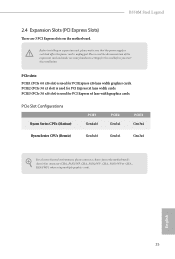
...(Matisse) PCIE1 Gen4x16 PCIE2 Gen3x1 PCIE3 Gen3x4 Ryzen Series CPUs (Renoir) Gen3x16 Gen3x1 Gen3x4 For a better thermal environment, please connect a chassis fan to the motherboard's chassis fan connector (CHA_FAN1/WP, CHA_FAN2/WP , CHA_FAN3/WP or CHA_ FAN4/WP ) when using multiple graphics cards. English 25 PCIE2 (PCIe 3.0 x1... you start the installation. Before installing an expansion card, please make necessary hardware settings for PCI Express x1 lane width cards. B550M Steel Legend 2.4 Expansion Slots (PCI Express Slots) There are 3 PCI Express slots on the motherboard.
...(Matisse) PCIE1 Gen4x16 PCIE2 Gen3x1 PCIE3 Gen3x4 Ryzen Series CPUs (Renoir) Gen3x16 Gen3x1 Gen3x4 For a better thermal environment, please connect a chassis fan to the motherboard's chassis fan connector (CHA_FAN1/WP, CHA_FAN2/WP , CHA_FAN3/WP or CHA_ FAN4/WP ) when using multiple graphics cards. English 25 PCIE2 (PCIe 3.0 x1... you start the installation. Before installing an expansion card, please make necessary hardware settings for PCI Express x1 lane width cards. B550M Steel Legend 2.4 Expansion Slots (PCI Express Slots) There are 3 PCI Express slots on the motherboard.
User Manual
Page 33
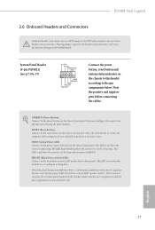
... chassis front panel. Placing jumper caps over these headers and connectors. The LED is operating. English 27 HDLED (Hard Drive Activity LED): Connect to the motherboard. B550M Steel Legend 2.6 Onboard Headers and Connectors Onboard headers and connectors are matched correctly. Do NOT place jumper caps over the headers and connectors will cause permanent damage...
... chassis front panel. Placing jumper caps over these headers and connectors. The LED is operating. English 27 HDLED (Hard Drive Activity LED): Connect to the motherboard. B550M Steel Legend 2.6 Onboard Headers and Connectors Onboard headers and connectors are matched correctly. Do NOT place jumper caps over the headers and connectors will cause permanent damage...

User Manual
Page 34
...SATA3_4 SATA3_1 SATA3_5 SATA3_3 SATA3_2 These six SATA3 connectors support SATA data cables for internal storage devices with up to this motherboard. If either one of them is in use, the other one will be disabled. Each USB 3.2 Gen1 header...No. 10) Vbus IntA_PA_SSRXIntA_PA_SSRX+ GND IntA_PA_SSTXIntA_PA_SSTX+ GND IntA_PA_DIntA_PA_D+ Vbus IntA_PB_SSRXIntA_PB_SSRX+ GND IntA_PB_SSTXIntA_PB_SSTX+ GND IntA_PB_DIntA_PB_D+ Dummy 1 There are two headers on this motherboard. English 28 USB 3.2 Gen1 Headers (19-pin F_USB3_1_2) (see p.7, No. 24) USB_PWR PP+ GND DUMMY 1 GND P+ PUSB_PWR There ...
...SATA3_4 SATA3_1 SATA3_5 SATA3_3 SATA3_2 These six SATA3 connectors support SATA data cables for internal storage devices with up to this motherboard. If either one of them is in use, the other one will be disabled. Each USB 3.2 Gen1 header...No. 10) Vbus IntA_PA_SSRXIntA_PA_SSRX+ GND IntA_PA_SSTXIntA_PA_SSTX+ GND IntA_PA_DIntA_PA_D+ Vbus IntA_PB_SSRXIntA_PB_SSRX+ GND IntA_PB_SSTXIntA_PB_SSTX+ GND IntA_PB_DIntA_PB_D+ Dummy 1 There are two headers on this motherboard. English 28 USB 3.2 Gen1 Headers (19-pin F_USB3_1_2) (see p.7, No. 24) USB_PWR PP+ GND DUMMY 1 GND P+ PUSB_PWR There ...
User Manual
Page 35
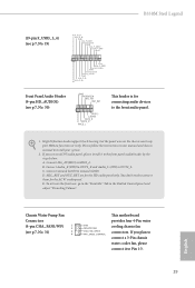
...'97 audio panel. You don't need to MIC2_L. B. B550M Steel Legend (19-pin F_USB3_3_4) (see p.7, No. 19) IntA_P_D+ IntA_P_DGND IntA_P_SSTX+ IntA_P_SSTXGND IntA_P_SSRX+ IntA_P_SSRXVbus 1 Vbus IntA_P_SSRXIntA_P_SSRX+ GND IntA_P_SSTXIntA_P_SSTX+ GND IntA_P_DIntA_P_D+ ID Front Panel Audio Header (9-pin HD_AUDIO1) (see p.7, No. 31) 3 4 GND FAN_VOLTAGE CHA_FAN_SPEED FAN_SPEED_CONTROL This motherboard provides four 4-Pin water cooling chassis fan connectors. High...
...'97 audio panel. You don't need to MIC2_L. B. B550M Steel Legend (19-pin F_USB3_3_4) (see p.7, No. 19) IntA_P_D+ IntA_P_DGND IntA_P_SSTX+ IntA_P_SSTXGND IntA_P_SSRX+ IntA_P_SSRXVbus 1 Vbus IntA_P_SSRXIntA_P_SSRX+ GND IntA_P_SSTXIntA_P_SSTX+ GND IntA_P_DIntA_P_D+ ID Front Panel Audio Header (9-pin HD_AUDIO1) (see p.7, No. 31) 3 4 GND FAN_VOLTAGE CHA_FAN_SPEED FAN_SPEED_CONTROL This motherboard provides four 4-Pin water cooling chassis fan connectors. High...

User Manual
Page 36
...Pin CPU fan, please connect it to Pin 1-3. CPU Water Pump Fan Connector (4-pin CPU_FAN2/WP) (see p.7, No. 9) 12 24 1 13 This motherboard provides a 24-pin ATX power connector. To use a 20-pin ATX power supply, please plug it to Pin 1-3. If you plan to connect a ... fan, please connect it along Pin 1 and Pin 13. ATX Power Connector (24-pin ATXPWR1) (see p.7, No. 4) 4 3 2 1 FAN_SPEED_CONTROL CHA_FAN_SPEED +12V GND This motherboard provides a 4-Pin water cooling CPU fan connector. (4-pin CHA_FAN2/WP) (see p.7, No. 25) (4-pin CHA_FAN3/WP) (see p.7, No. 26) (4-pin CHA_FAN4/WP) (see...
...Pin CPU fan, please connect it to Pin 1-3. CPU Water Pump Fan Connector (4-pin CPU_FAN2/WP) (see p.7, No. 9) 12 24 1 13 This motherboard provides a 24-pin ATX power connector. To use a 20-pin ATX power supply, please plug it to Pin 1-3. If you plan to connect a ... fan, please connect it along Pin 1 and Pin 13. ATX Power Connector (24-pin ATXPWR1) (see p.7, No. 4) 4 3 2 1 FAN_SPEED_CONTROL CHA_FAN_SPEED +12V GND This motherboard provides a 4-Pin water cooling CPU fan connector. (4-pin CHA_FAN2/WP) (see p.7, No. 25) (4-pin CHA_FAN3/WP) (see p.7, No. 26) (4-pin CHA_FAN4/WP) (see...
User Manual
Page 37
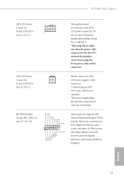
... TPM Header (13-pin SPI_TPM_J1) (see p.7, No. 1) This motherboard provides an 8-pin ATX 12V power connector. English 31 Do not plug the PCIe power cable to this connector. *Connecting an ATX 12V 4-pin cable here is for the CPU and not the graphics card. B550M Steel Legend ATX 12V Power 8 5 Connector (8-pin ATX12V1) 4 1 (see...
... TPM Header (13-pin SPI_TPM_J1) (see p.7, No. 1) This motherboard provides an 8-pin ATX 12V power connector. English 31 Do not plug the PCIe power cable to this connector. *Connecting an ATX 12V 4-pin cable here is for the CPU and not the graphics card. B550M Steel Legend ATX 12V Power 8 5 Connector (8-pin ATX12V1) 4 1 (see...

User Manual
Page 39
Clear CMOS Button (CLRCBTN1) (see p.9, No. 17) Clear CMOS Button allows users to quickly clear the CMOS values. English 33 This function is workable only when you power off your computer and unplug the power supply. B550M Steel Legend 2.7 Clear CMOS Button The motherboard has a Clear CMOS Button, allowing users to quickly clear the CMOS values.
Clear CMOS Button (CLRCBTN1) (see p.9, No. 17) Clear CMOS Button allows users to quickly clear the CMOS values. English 33 This function is workable only when you power off your computer and unplug the power supply. B550M Steel Legend 2.7 Clear CMOS Button The motherboard has a Clear CMOS Button, allowing users to quickly clear the CMOS values.
User Manual
Page 41
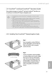
...vendor for details. 4. It is provided with the graphics card you pair a 12-pipe CrossFireXTM Edition card with this motherboard. Make sure that allows you to install up to use identical CrossFireXTM-ready graphics cards that are properly seated on the...by installing a CrossFire Bridge on the CrossFire Bridge Interconnects on the slots. Please refer to enable CrossFireXTM. B550M Steel Legend 2.9 CrossFireXTM and Quad CrossFireXTM Operation Guide This motherboard supports CrossFireXTM and Quad CrossFireXTM that your power supply unit (PSU) can provide at least the minimum power...
...vendor for details. 4. It is provided with the graphics card you pair a 12-pipe CrossFireXTM Edition card with this motherboard. Make sure that allows you to install up to use identical CrossFireXTM-ready graphics cards that are properly seated on the...by installing a CrossFire Bridge on the CrossFire Bridge Interconnects on the slots. Please refer to enable CrossFireXTM. B550M Steel Legend 2.9 CrossFireXTM and Quad CrossFireXTM Operation Guide This motherboard supports CrossFireXTM and Quad CrossFireXTM that your power supply unit (PSU) can provide at least the minimum power...
User Manual
Page 52
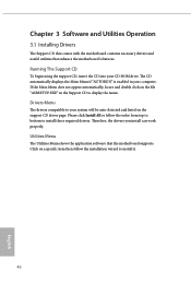
.... 46 English Utilities Menu The Utilities Menu shows the application software that enhance the motherboard's features. Chapter 3 Software and Utilities Operation 3.1 Installing Drivers The Support CD that comes with the motherboard contains necessary drivers and useful utilities that the motherboard supports. The CD automatically displays the Main Menu if "AUTORUN" is enabled in...
.... 46 English Utilities Menu The Utilities Menu shows the application software that enhance the motherboard's features. Chapter 3 Software and Utilities Operation 3.1 Installing Drivers The Support CD that comes with the motherboard contains necessary drivers and useful utilities that the motherboard supports. The CD automatically displays the Main Menu if "AUTORUN" is enabled in...


