

User Manual
Page 4
...I/O Panel 8 Chapter 2 Installation 10 2.1 Installing the CPU 11 2.2 Installing the CPU Fan and Heatsink 14 2.3 Installing Memory Modules (DIMM) 15 2.4 Expansion Slots (PCI Express Slots) 17 2.5 Jumpers Setup 18 2.6 Onboard Headers and Connectors 19 2.7 CrossFireXTM and Quad CrossFireXTM Operation Guide 23 2.7.1 Installing Two CrossFireXTM-Ready Graphics Cards 23 2.7.2 Driver Installation and Setup 25 Chapter 3 Software and Utilities Operation 26 3.1 Installing Drivers 26 3.2 ASRock Live Update & APP Shop 27 3.2.1 UI Overview 27 3.2.2 Apps 28 3.2.3 BIOS & Drivers...
...I/O Panel 8 Chapter 2 Installation 10 2.1 Installing the CPU 11 2.2 Installing the CPU Fan and Heatsink 14 2.3 Installing Memory Modules (DIMM) 15 2.4 Expansion Slots (PCI Express Slots) 17 2.5 Jumpers Setup 18 2.6 Onboard Headers and Connectors 19 2.7 CrossFireXTM and Quad CrossFireXTM Operation Guide 23 2.7.1 Installing Two CrossFireXTM-Ready Graphics Cards 23 2.7.2 Driver Installation and Setup 25 Chapter 3 Software and Utilities Operation 26 3.1 Installing Drivers 26 3.2 ASRock Live Update & APP Shop 27 3.2.1 UI Overview 27 3.2.2 Apps 28 3.2.3 BIOS & Drivers...
User Manual
Page 6
...; ASRock B150M Pro4S Motherboard (Micro ATX Form Factor) • ASRock B150M Pro4S Quick Installation Guide • ASRock B150M Pro4S Support CD • 2 x Serial ATA (SATA) Data Cables (Optional) • 1 x I/O Panel Shield 1 English In this documentation, Chapter 1 and 2 contains the introduction of the sotware and utilities. In case any modiications of this documentation occur, the updated version will be available on ASRock's website as well. If you are using. You may ind the latest VGA cards and CPU support list on ASRock...
...; ASRock B150M Pro4S Motherboard (Micro ATX Form Factor) • ASRock B150M Pro4S Quick Installation Guide • ASRock B150M Pro4S Support CD • 2 x Serial ATA (SATA) Data Cables (Optional) • 1 x I/O Panel Shield 1 English In this documentation, Chapter 1 and 2 contains the introduction of the sotware and utilities. In case any modiications of this documentation occur, the updated version will be available on ASRock's website as well. If you are using. You may ind the latest VGA cards and CPU support list on ASRock...
User Manual
Page 8
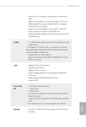
B150M Pro4S • Supports DVI-D with LED (ACT/LINK LED and SPEED LED) • HD Audio Jacks: Line in / Front Speaker / Microphone Storage • 6 x SATA3 6.0 Gb/s Connectors, support NCQ, AHCI and Hot Plug 3 English resolution up to 1920x1200 @ 60Hz • Supports Auto Lip Sync, Deep Color (12bpc), xvYCC and HBR (High Bit Rate Audio) with HDMI Port (Compliant HDMI monitor is required) • Supports Accelerated Media Codecs: HEVC, VP8, VP9 • Supports HDCP with DVI-D and...
B150M Pro4S • Supports DVI-D with LED (ACT/LINK LED and SPEED LED) • HD Audio Jacks: Line in / Front Speaker / Microphone Storage • 6 x SATA3 6.0 Gb/s Connectors, support NCQ, AHCI and Hot Plug 3 English resolution up to 1920x1200 @ 60Hz • Supports Auto Lip Sync, Deep Color (12bpc), xvYCC and HBR (High Bit Rate Audio) with HDMI Port (Compliant HDMI monitor is required) • Supports Accelerated Media Codecs: HEVC, VP8, VP9 • Supports HDCP with DVI-D and...

User Manual
Page 9
..., DRAM, VPPM, PCH 1.0V, VCCIO, VCCSA OS • Microsot® Windows® 10 64-bit / 8.1 64-bit / 7 32-bit / 7 64- Connector • 1 x Print Port Header • 1 x COM Port Header • 1 x TPM Header • 1 x Chassis Intrusion and Speaker Header • 1 x CPU Fan Connector (4-pin) (Smart Fan Speed Control) • 2 x Chassis Fan Connectors (4-pin) (Smart Fan Speed Control) • 1 x 24 pin ATX Power Connector • 1 x 8 pin 12V Power Connector • 1 x Front Panel Audio Connector • 1 x USB 2.0 Header (Supports 2 USB 2.0 ports) (Supports ESD Protection (ASRock...
..., DRAM, VPPM, PCH 1.0V, VCCIO, VCCSA OS • Microsot® Windows® 10 64-bit / 8.1 64-bit / 7 32-bit / 7 64- Connector • 1 x Print Port Header • 1 x COM Port Header • 1 x TPM Header • 1 x Chassis Intrusion and Speaker Header • 1 x CPU Fan Connector (4-pin) (Smart Fan Speed Control) • 2 x Chassis Fan Connectors (4-pin) (Smart Fan Speed Control) • 1 x 24 pin ATX Power Connector • 1 x 8 pin 12V Power Connector • 1 x Front Panel Audio Connector • 1 x USB 2.0 Header (Supports 2 USB 2.0 ports) (Supports ESD Protection (ASRock...

User Manual
Page 22
... (PCIe 3.0 x1 slot) is unplugged. PCIe Slot Conigurations Single Graphics Card PCIE1 x16 PCIE4 N/A Two Graphics Cards in CrossFireXTM Mode x16 x4 For a better thermal environment, please connect a chassis fan to the motherboard's chassis fan connector (CHA_FAN1 or CHA_FAN2) when using multiple graphics cards. Before installing an expansion card, please make necessary hardware settings for the card before you start the installation. Please read the documentation of the expansion card and make sure that the power supply is switched...
... (PCIe 3.0 x1 slot) is unplugged. PCIe Slot Conigurations Single Graphics Card PCIE1 x16 PCIE4 N/A Two Graphics Cards in CrossFireXTM Mode x16 x4 For a better thermal environment, please connect a chassis fan to the motherboard's chassis fan connector (CHA_FAN1 or CHA_FAN2) when using multiple graphics cards. Before installing an expansion card, please make necessary hardware settings for the card before you start the installation. Please read the documentation of the expansion card and make sure that the power supply is switched...

User Manual
Page 23
... 15 seconds, use a jumper cap to short pin2 and pin3 on the pins, the jumper is "Open". Please be noted that the password, date, time, and user default proile will be detected. Please adjust the BIOS option "Clear Status" to default setup, please turn of previous chassis intrusion status. Clear CMOS Jumper (CLRMOS1) (see p.6, No. 16) Default Clear CMOS CLRMOS1 allows you update the BIOS. To clear and reset the system parameters to clear the record...
... 15 seconds, use a jumper cap to short pin2 and pin3 on the pins, the jumper is "Open". Please be noted that the password, date, time, and user default proile will be detected. Please adjust the BIOS option "Clear Status" to default setup, please turn of previous chassis intrusion status. Clear CMOS Jumper (CLRMOS1) (see p.6, No. 16) Default Clear CMOS CLRMOS1 allows you update the BIOS. To clear and reset the system parameters to clear the record...

User Manual
Page 24
... your chassis front panel module to this header according to this header, make sure the wire assignments and the pin assignments are NOT jumpers. English 19 B150M Pro4S 2.6 Onboard Headers and Connectors Onboard headers and connectors are matched correctly. RESET (Reset Switch): Connect to perform a normal restart. HDLED (Hard Drive Activity LED): Connect to the power switch on the chassis to the pin assignments below. System Panel Header (9-pin PANEL1) (see p.6, No. 14) PLED+ PLEDPWRBTN# GND 1 GND RESET# GND HDLEDHDLED+ Connect the power switch, reset switch...
... your chassis front panel module to this header according to this header, make sure the wire assignments and the pin assignments are NOT jumpers. English 19 B150M Pro4S 2.6 Onboard Headers and Connectors Onboard headers and connectors are matched correctly. RESET (Reset Switch): Connect to perform a normal restart. HDLED (Hard Drive Activity LED): Connect to the power switch on the chassis to the pin assignments below. System Panel Header (9-pin PANEL1) (see p.6, No. 14) PLED+ PLEDPWRBTN# GND 1 GND RESET# GND HDLEDHDLED+ Connect the power switch, reset switch...
User Manual
Page 26
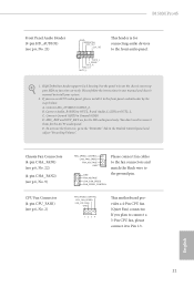
... J_SENSE OUT2_R MIC2_R MIC2_L his motherboard provides a 4-Pin CPU fan (Quiet Fan) connector. B150M Pro4S Front Panel Audio Header (9-pin HD_AUDIO1) (see p.6, No. 2) FAN_SPEED_CONTROL CHA_FAN_SPEED FAN_VOLTAGE GND GND FAN_VOLTAGE CHA_FAN_SPEED FAN_SPEED_CONTROL Please connect fan cables to the fan connectors and match the black wire to the ground pin. High Deinition Audio supports Jack Sensing, but the panel wire on the chassis must support HDA to MIC2_L. Please follow the instructions in the Realtek Control panel and adjust "Recording Volume...
... J_SENSE OUT2_R MIC2_R MIC2_L his motherboard provides a 4-Pin CPU fan (Quiet Fan) connector. B150M Pro4S Front Panel Audio Header (9-pin HD_AUDIO1) (see p.6, No. 2) FAN_SPEED_CONTROL CHA_FAN_SPEED FAN_VOLTAGE GND GND FAN_VOLTAGE CHA_FAN_SPEED FAN_SPEED_CONTROL Please connect fan cables to the fan connectors and match the black wire to the ground pin. High Deinition Audio supports Jack Sensing, but the panel wire on the chassis must support HDA to MIC2_L. Please follow the instructions in the Realtek Control panel and adjust "Recording Volume...
User Manual
Page 28
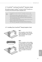
... your power supply unit (PSU) can provide at least the minimum power your graphics card driver supports AMD CrossFireXTM technology. Make sure that your system requires. B150M Pro4S 2.7 CrossFireXTM and Quad CrossFireXTM Operation Guide his motherboard supports CrossFireXTM and Quad CrossFireXTM that allows you to install up to enable CrossFireXTM. Please refer to AMD graphics card manuals for detailed installation guide. 2.7.1 Installing Two CrossFireXTM-Ready Graphics Cards Step 1 Insert one graphics card into PCIE1 slot and the other graphics card...
... your power supply unit (PSU) can provide at least the minimum power your graphics card driver supports AMD CrossFireXTM technology. Make sure that your system requires. B150M Pro4S 2.7 CrossFireXTM and Quad CrossFireXTM Operation Guide his motherboard supports CrossFireXTM and Quad CrossFireXTM that allows you to install up to enable CrossFireXTM. Please refer to AMD graphics card manuals for detailed installation guide. 2.7.1 Installing Two CrossFireXTM-Ready Graphics Cards Step 1 Insert one graphics card into PCIE1 slot and the other graphics card...
User Manual
Page 31
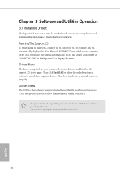
... Support CD to install it. herefore, the drivers you install can work properly. Running The Support CD To begin using the support CD, insert the CD into your computer. If the Main Menu does not appear automatically, locate and double click on the ile "ASRSETUP.EXE" in your CD-ROM drive. Please click Install All or follow the installation wizard to display the menu. To improve Windows 7 compatibility, please download...
... Support CD to install it. herefore, the drivers you install can work properly. Running The Support CD To begin using the support CD, insert the CD into your computer. If the Main Menu does not appear automatically, locate and double click on the ile "ASRSETUP.EXE" in your CD-ROM drive. Please click Install All or follow the installation wizard to display the menu. To improve Windows 7 compatibility, please download...
User Manual
Page 38
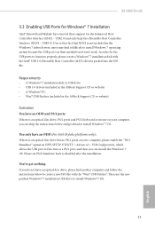
... use the new patched Windows® 7 installation USB drive to disabled ater the installation. USB2.0) and only kept the eXtensible Host Controller Interface (XHCI - You only have an ODD and PS/2 ports: If there is not included in UEFI SETUP UTILITY > Advanced > USB Coniguration, which allows the USB port to install Windows 7 operating system because the USB ports on your computer, please enable the "PS/2 Simulator" option in the Windows 7 inbox drivers, users may...
... use the new patched Windows® 7 installation USB drive to disabled ater the installation. USB2.0) and only kept the eXtensible Host Controller Interface (XHCI - You only have an ODD and PS/2 ports: If there is not included in UEFI SETUP UTILITY > Advanced > USB Coniguration, which allows the USB port to install Windows 7 operating system because the USB ports on your computer, please enable the "PS/2 Simulator" option in the Windows 7 inbox drivers, users may...
User Manual
Page 39
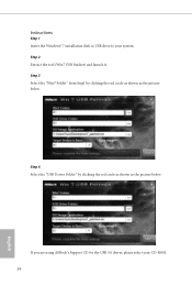
Step 2 Extract the tool (Win7 USB Patcher) and launch it. If you are using ASRock's Support CD for the USB 3.0 driver, please select your system. Instructions Step 1 Insert the Windows® 7 installation disk or USB drive to your CD-ROM. 34 English Step 3 Select the "Win7 Folder" from Step1 by clicking the red circle as shown as the picture below . Step 4 Select the "USB Driver Folder" by clicking the red circle as shown as the picture below .
Step 2 Extract the tool (Win7 USB Patcher) and launch it. If you are using ASRock's Support CD for the USB 3.0 driver, please select your system. Instructions Step 1 Insert the Windows® 7 installation disk or USB drive to your CD-ROM. 34 English Step 3 Select the "Win7 Folder" from Step1 by clicking the red circle as shown as the picture below . Step 4 Select the "USB Driver Folder" by clicking the red circle as shown as the picture below .

User Manual
Page 41
... being updated, the following selections: Main For setting system time/date information OC Tweaker For overclocking conigurations Advanced For advanced system conigurations Tool Useful tools H/W Monitor Displays current hardware status Boot For coniguring boot settings and boot priority Security For security settings Exit Exit the current screen or the UEFI Setup Utility English 36 Chapter 4 UEFI SETUP UTILITY 4.1 Introduction his section explains how to use the UEFI SETUP UTILITY to enter the UEFI SETUP UTILITY ater POST, restart...
... being updated, the following selections: Main For setting system time/date information OC Tweaker For overclocking conigurations Advanced For advanced system conigurations Tool Useful tools H/W Monitor Displays current hardware status Boot For coniguring boot settings and boot priority Security For security settings Exit Exit the current screen or the UEFI Setup Utility English 36 Chapter 4 UEFI SETUP UTILITY 4.1 Introduction his section explains how to use the UEFI SETUP UTILITY to enter the UEFI SETUP UTILITY ater POST, restart...

User Manual
Page 55
... PCIE devices. PCIE ASPM Support his option enables/disables the control of ASPM on CPU side of manageability, security, isolation, and I/O performance. PCIE1 Link Speed Select the link speed for Directed I/O helps your virtual machine monitor better utilize hardware by improving application compatibility and reliability, and providing additional levels of the DMI Link. 50 English DMI ASPM Support his option enables/disables the ASPM support for all CPU downstream devices. 4.4.2 Chipset Coniguration Primary Graphics...
... PCIE devices. PCIE ASPM Support his option enables/disables the control of ASPM on CPU side of manageability, security, isolation, and I/O performance. PCIE1 Link Speed Select the link speed for Directed I/O helps your virtual machine monitor better utilize hardware by improving application compatibility and reliability, and providing additional levels of the DMI Link. 50 English DMI ASPM Support his option enables/disables the ASPM support for all CPU downstream devices. 4.4.2 Chipset Coniguration Primary Graphics...

User Manual
Page 56
... audio and automatically disable it when a sound card is selected, the system will start to boot up . Set to Auto to disable the integrated graphics when an external graphics card is allocated to keep the integrated graphics enabled at all PCH DMI devices. Onboard Debug Port LED Enable/disable the onboard Dr. Debug LED. 51 English Share Memory Conigure the size of the Power and Keyboard LEDs when the system enters into Standby/Hibernation mode. B150M Pro4S PCH DMI ASPM Support his option enables/disables...
... audio and automatically disable it when a sound card is selected, the system will start to boot up . Set to Auto to disable the integrated graphics when an external graphics card is allocated to keep the integrated graphics enabled at all PCH DMI devices. Onboard Debug Port LED Enable/disable the onboard Dr. Debug LED. 51 English Share Memory Conigure the size of the Power and Keyboard LEDs when the system enters into Standby/Hibernation mode. B150M Pro4S PCH DMI ASPM Support his option enables/disables...

User Manual
Page 58
4.4.4 Super IO Coniguration B150M Pro4S Serial Port Enable or disable the Serial port. Serial Port Address Select the address of the Parallel port. PS2 Y-Cable Enable the PS2 Y-Cable or set this option to your connected device. Change Settings Select the address of the Serial port. Device Mode Select the device mode according to Auto. 53 English Parallel Port Enable or disable the Parallel port.
4.4.4 Super IO Coniguration B150M Pro4S Serial Port Enable or disable the Serial port. Serial Port Address Select the address of the Parallel port. PS2 Y-Cable Enable the PS2 Y-Cable or set this option to your connected device. Change Settings Select the address of the Serial port. Device Mode Select the device mode according to Auto. 53 English Parallel Port Enable or disable the Parallel port.

User Manual
Page 61
his should be enabled for the complete USB keyboard legacy support for USB 2.0 devices. Select UEFI Setup Only to disable legacy USB support. If you install Windows 7. 56 English Port 60/64 Emulation Enable the support of I/O port 60h/64h emulation. 4.4.6 USB Coniguration Legacy USB Support Enable or disable Legacy OS Support for non-USB aware OS. *Enable this option if you encounter USB compatibility issues it is recommended to support USB devices under the UEFI setup and Windows/Linux operating systems only.
his should be enabled for the complete USB keyboard legacy support for USB 2.0 devices. Select UEFI Setup Only to disable legacy USB support. If you install Windows 7. 56 English Port 60/64 Emulation Enable the support of I/O port 60h/64h emulation. 4.4.6 USB Coniguration Legacy USB Support Enable or disable Legacy OS Support for non-USB aware OS. *Enable this option if you encounter USB compatibility issues it is recommended to support USB devices under the UEFI setup and Windows/Linux operating systems only.

User Manual
Page 63
... tool in the UEFI that installs the LAN driver to modify the system time are required. Easy Driver Installer For users that don't have an optical disk drive to install the drivers from bypassing OMG, guest accounts without permission to your current PC and the devices connected. You may schedule the starting and ending hours of your system via OMG. Please setup network coniguration before using UEFI Tech Service.
... tool in the UEFI that installs the LAN driver to modify the system time are required. Easy Driver Installer For users that don't have an optical disk drive to install the drivers from bypassing OMG, guest accounts without permission to your current PC and the devices connected. You may schedule the starting and ending hours of your system via OMG. Please setup network coniguration before using UEFI Tech Service.

User Manual
Page 65
... Flash. *For BIOS backup and recovery purpose, it is enabled. Network Coniguration Use this function. he higher the value, the faster the fan speed. Internet Flash - Max: 255 Min: 1 Instant Flash Save UEFI iles in your USB storage device and run Instant Flash to update your USB pen drive before using this to the secondary lash ROM. Secure Backup UEFI Whenever one of the CPU fan while Dehumidiier is recommended to plug in your UEFI. Dehumidiier CPU Fan Setting...
... Flash. *For BIOS backup and recovery purpose, it is enabled. Network Coniguration Use this function. he higher the value, the faster the fan speed. Internet Flash - Max: 255 Min: 1 Instant Flash Save UEFI iles in your USB storage device and run Instant Flash to update your USB pen drive before using this to the secondary lash ROM. Secure Backup UEFI Whenever one of the CPU fan while Dehumidiier is recommended to plug in your UEFI. Dehumidiier CPU Fan Setting...

User Manual
Page 69
.... User Password Set or change the password for the user account. Intel(R) Platform Trust Technology Enable/disable Intel PTT in the UEFI Setup Utility. Leave it blank and press enter to remove the password. You may set or change the supervisor/user password for Windows 8.1 Secure Boot. Leave it blank and press enter to remove the password. Secure Boot Use this item to change the settings in the UEFI Setup Utility. Users are unable to enable or disable support for the system. Disable this option to change the settings...
.... User Password Set or change the password for the user account. Intel(R) Platform Trust Technology Enable/disable Intel PTT in the UEFI Setup Utility. Leave it blank and press enter to remove the password. You may set or change the supervisor/user password for Windows 8.1 Secure Boot. Leave it blank and press enter to remove the password. Secure Boot Use this item to change the settings in the UEFI Setup Utility. Users are unable to enable or disable support for the system. Disable this option to change the settings...


