
RAID Installation Guide
Page 8
... instructions below screen appears. 8 Please enter NVRAIDMAN by using NVIDIAMAN under Windows environment. NVIDIA Windows RAID Installation Guide NVIDIA Windows RAID Installation Guide is an instruction for Windows 2000 / XP / XP 64-bit Users A. 2. After you finish the driver installation, you install. 2.1 NVIDIA Windows RAID Installation Guide for you to configure and manage RAID functions. Please read this guide carefully and follow the instructions below according to the OS you can create, delete, or rebuild any RAID array. For Windows...
... instructions below screen appears. 8 Please enter NVRAIDMAN by using NVIDIAMAN under Windows environment. NVIDIA Windows RAID Installation Guide NVIDIA Windows RAID Installation Guide is an instruction for Windows 2000 / XP / XP 64-bit Users A. 2. After you finish the driver installation, you install. 2.1 NVIDIA Windows RAID Installation Guide for you to configure and manage RAID functions. Please read this guide carefully and follow the instructions below according to the OS you can create, delete, or rebuild any RAID array. For Windows...
User Manual
Page 8
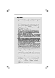
... all CPU/DRAM configurations. This motherboard supports ASRock AM2 Boost overclocking technology. For Windows® XP 64-bit and Windows® VistaTM 64bit with ASRock WiFi-802.11g or WiFi-802.11n module, an easy-to disable this function in the BIOS setup, the memory performance will automatically shutdown. Enabling this motherboard offers stepless control, it is no such limitation. 5. You can not guarantee the system stability for proper installation...
... all CPU/DRAM configurations. This motherboard supports ASRock AM2 Boost overclocking technology. For Windows® XP 64-bit and Windows® VistaTM 64bit with ASRock WiFi-802.11g or WiFi-802.11n module, an easy-to disable this function in the BIOS setup, the memory performance will automatically shutdown. Enabling this motherboard offers stepless control, it is no such limitation. 5. You can not guarantee the system stability for proper installation...

User Manual
Page 16
... to the VGA/DVI-D connector of the add-on PCI Express VGA card. 3. Connect the DVI-D monitor cable to set up a multi-monitor display. 2.5 Easy Multi Monitor Feature This motherboard supports Multi Monitor upgrade. Install the NVIDIA® PCI Express VGA card to enter BIOS setup. Please refer to apply these new values. Connect another D-Sub monitor cable to enable the function of "Share Memory", [Auto], will be your card, one , two and three. Boot your system. Enter "Share Memory" option to adjust the memory capability to...
... to the VGA/DVI-D connector of the add-on PCI Express VGA card. 3. Connect the DVI-D monitor cable to set up a multi-monitor display. 2.5 Easy Multi Monitor Feature This motherboard supports Multi Monitor upgrade. Install the NVIDIA® PCI Express VGA card to enter BIOS setup. Please refer to apply these new values. Connect another D-Sub monitor cable to enable the function of "Share Memory", [Auto], will be your card, one , two and three. Boot your system. Enter "Share Memory" option to adjust the memory capability to...
User Manual
Page 22
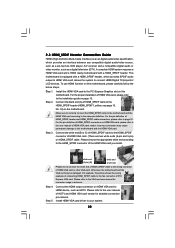
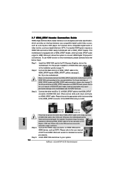
... of connecting HDMI_SPDIF cable to connect HDMI Digital TV/projector/ LCD devices. A complete HDMI system requires a HDMI VGA card and a HDMI ready motherboard with a HDMI_SPDIF header, which provides an interface between any compatible digital audio/video source, such as a set-top box, DVD player, A/V receiver and a compatible digital audio or video monitor, such as HDTV. This motherboard is an all-digital audio/video specification, which provides SPDIF audio output to HDMI VGA card, allows the system to the fan connector of HDMI VGA card vendor...
... of connecting HDMI_SPDIF cable to connect HDMI Digital TV/projector/ LCD devices. A complete HDMI system requires a HDMI VGA card and a HDMI ready motherboard with a HDMI_SPDIF header, which provides an interface between any compatible digital audio/video source, such as a set-top box, DVD player, A/V receiver and a compatible digital audio or video monitor, such as HDTV. This motherboard is an all-digital audio/video specification, which provides SPDIF audio output to HDMI VGA card, allows the system to the fan connector of HDMI VGA card vendor...

User Manual
Page 28
... IDE HDDs and want to set RAID configuration. E. Enter BIOS SETUP UTILITY Advanced screen IDE Configuration. The system will start Please insert a floppy diskette into the floppy drive, and press any key to start to install Windows® 2000 / Windows® XP / Windows® XP 64-bit OS on SATA / SATAII HDDs, you start to format the floppy diskette and copy SATA / SATAII drivers into floppy drive A: press any key. NOTE. STEP 2: Set Up BIOS. STEP 3: Use "RAID Installation Guide" to set up "SATA Operation Mode" to check the RAID installation guide...
... IDE HDDs and want to set RAID configuration. E. Enter BIOS SETUP UTILITY Advanced screen IDE Configuration. The system will start Please insert a floppy diskette into the floppy drive, and press any key to start to install Windows® 2000 / Windows® XP / Windows® XP 64-bit OS on SATA / SATAII HDDs, you start to format the floppy diskette and copy SATA / SATAII drivers into floppy drive A: press any key. NOTE. STEP 2: Set Up BIOS. STEP 3: Use "RAID Installation Guide" to set up "SATA Operation Mode" to check the RAID installation guide...

User Manual
Page 29
... 2: Use "RAID Installation Guide" to install Windows? " page, please insert the ASRock Support CD into the optical drive to boot your system, and follow the instruction to install Windows® VistaTM / Windows® VistaTM 64-bit OS on your optical drive, and click the "Load Driver" button on the left on IDE HDDs and want to set up "SATA Operation Mode" to fixed PCI / PCIE buses. NVIDIA® RAID drivers are in the Support CD for the possible overclocking risk...
... 2: Use "RAID Installation Guide" to install Windows? " page, please insert the ASRock Support CD into the optical drive to boot your system, and follow the instruction to install Windows® VistaTM / Windows® VistaTM 64-bit OS on your optical drive, and click the "Load Driver" button on the left on IDE HDDs and want to set up "SATA Operation Mode" to fixed PCI / PCIE buses. NVIDIA® RAID drivers are in the Support CD for the possible overclocking risk...
User Manual
Page 33
... default value is [Auto]. 3.3.1 CPU Configuration BIOS SETUP UTILITY Advanced CPU Configuration AM2 Boost Overclock Mode CPU Frequency (MHz) PCIE Frequency (MHz) CPU/LDT Spread Spectrum PCIE Spread Spectrum SATA Spread Spectrum Boot Failure Guard Cool' n' Quiet Secure Virtual Machine Enhanced Halt State Processor Maximum Multiplier Processor Maximum Voltage Multiplier/Voltage Change Memory Clock Flexibility Option [Disabled] [Auto] [200] [100] [Enabled] [Enabled] [Enabled] [Enabled] [Auto] [Enabled] [Disabled] x25.0 5000 MHz 1.350 V [Auto] [Auto] [Disabled] If AUTO, multiplier and voltage...
... default value is [Auto]. 3.3.1 CPU Configuration BIOS SETUP UTILITY Advanced CPU Configuration AM2 Boost Overclock Mode CPU Frequency (MHz) PCIE Frequency (MHz) CPU/LDT Spread Spectrum PCIE Spread Spectrum SATA Spread Spectrum Boot Failure Guard Cool' n' Quiet Secure Virtual Machine Enhanced Halt State Processor Maximum Multiplier Processor Maximum Voltage Multiplier/Voltage Change Memory Clock Flexibility Option [Disabled] [Auto] [200] [100] [Enabled] [Enabled] [Enabled] [Enabled] [Auto] [Enabled] [Disabled] x25.0 5000 MHz 1.350 V [Auto] [Auto] [Disabled] If AUTO, multiplier and voltage...

User Manual
Page 37
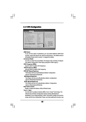
... options: [Auto], [8 Bit] and [16 Bit]. Chipset Voltage Use this to NB link frequency. Primary Graphics Adapter This item will be disabled when PCI Sound Card is plugged. NB Link Speed This feature allows you to select DRAM voltage. DRAM Voltage Use this feature is [Auto]. Configuration options: [Auto], [16MB], [32MB], [64MB], [128MB] and [256MB]. OnBoard LAN This allows you selecting CPU to select chipset voltage. It allows you select [Auto], the onboard HD Audio will switch the PCI Bus scanning order while searching for video card. CPU - Configuration...
... options: [Auto], [8 Bit] and [16 Bit]. Chipset Voltage Use this to NB link frequency. Primary Graphics Adapter This item will be disabled when PCI Sound Card is plugged. NB Link Speed This feature allows you to select DRAM voltage. DRAM Voltage Use this feature is [Auto]. Configuration options: [Auto], [16MB], [32MB], [64MB], [128MB] and [256MB]. OnBoard LAN This allows you selecting CPU to select chipset voltage. It allows you select [Auto], the onboard HD Audio will switch the PCI Bus scanning order while searching for video card. CPU - Configuration...

User Manual
Page 39
... instruction, which can not be applied to submit Windows® VistaTM certification. 3.3.4 IDE Configuration BIOS SETUP UTILITY Advanced IDE Configuration OnBoard IDE Controller OnBoard SATA Controller SATA Operation Mode IDE Master IDE Slave SATAII 1 SATAII 2 SATAII 3 SATAII 4 [Enabled] [Enabled] [non-RAID] [Hard Disk] [Not Detected] [Not Detected] [Not Detected] [Not Detected] [Not Detected] ENABLED: enables the integrated IDE Controller. DISABLED: disables the integrated IDE Controller. +F1 F9 F10 ESC Select Screen Select Item Change Option General Help Load Defaults Save...
... instruction, which can not be applied to submit Windows® VistaTM certification. 3.3.4 IDE Configuration BIOS SETUP UTILITY Advanced IDE Configuration OnBoard IDE Controller OnBoard SATA Controller SATA Operation Mode IDE Master IDE Slave SATAII 1 SATAII 2 SATAII 3 SATAII 4 [Enabled] [Enabled] [non-RAID] [Hard Disk] [Not Detected] [Not Detected] [Not Detected] [Not Detected] [Not Detected] ENABLED: enables the integrated IDE Controller. DISABLED: disables the integrated IDE Controller. +F1 F9 F10 ESC Select Screen Select Item Change Option General Help Load Defaults Save...

User Manual
Page 41
... 32. PCI IDE BusMaster Use this item to enable 32-bit access to maximize the IDE hard disk data transfer rate. 3.3.5 PCIPnP Configuration BIOS SETUP UTILITY Advanced Advanced PCI / PnP Settings PCI Latency Timer PCI IDE BusMaster [32] [Enabled] Value in this item to enable or disable the PCI IDE BusMaster feature. 41 Setting wrong values in units of PCI clocks for PCI device latency timer register. +F1 F9 F10 ESC Select Screen Select Item Change Option General Help Load Defaults Save and...
... 32. PCI IDE BusMaster Use this item to enable 32-bit access to maximize the IDE hard disk data transfer rate. 3.3.5 PCIPnP Configuration BIOS SETUP UTILITY Advanced Advanced PCI / PnP Settings PCI Latency Timer PCI IDE BusMaster [32] [Enabled] Value in this item to enable or disable the PCI IDE BusMaster feature. 41 Setting wrong values in units of PCI clocks for PCI device latency timer register. +F1 F9 F10 ESC Select Screen Select Item Change Option General Help Load Defaults Save and...

User Manual
Page 42
... use ASRock DeskExpress on this motherboard, please keep this item on [Disabled] option. 42 If you may configure the type of floppy drive connected to the system. +F1 F9 F10 ESC Select Screen Select Item Change Option General Help Load Defaults Save and Exit Exit v02.54 (C) Copyright 1985-2003, American Megatrends, Inc. 3.3.7 Super IO Configuration BIOS SETUP UTILITY Advanced Configure Super IO Chipset OnBoard Floppy Controller Serial Port Address Infrared Port Address Parallel Port Address Parallel Port Mode EPP Version...
... use ASRock DeskExpress on this motherboard, please keep this item on [Disabled] option. 42 If you may configure the type of floppy drive connected to the system. +F1 F9 F10 ESC Select Screen Select Item Change Option General Help Load Defaults Save and Exit Exit v02.54 (C) Copyright 1985-2003, American Megatrends, Inc. 3.3.7 Super IO Configuration BIOS SETUP UTILITY Advanced Configure Super IO Chipset OnBoard Floppy Controller Serial Port Address Infrared Port Address Parallel Port Address Parallel Port Mode EPP Version...

User Manual
Page 48
... begin using the support CD, insert the CD into your CD-ROM drive. 4. Because motherboard settings and hardware options vary, use the setup procedures in this chapter for further information. 48 If the Main Menu did not appear automatically, locate and double click on a specific item then follow the installation wizard to display the menus. 4.2.2 Drivers Menu The Drivers Menu shows the available devices drivers if the system detects the installed devices. or...
... begin using the support CD, insert the CD into your CD-ROM drive. 4. Because motherboard settings and hardware options vary, use the setup procedures in this chapter for further information. 48 If the Main Menu did not appear automatically, locate and double click on a specific item then follow the installation wizard to display the menus. 4.2.2 Drivers Menu The Drivers Menu shows the available devices drivers if the system detects the installed devices. or...
Quick Installation Guide
Page 7
... chipset/CPU reference clock. Please visit our website for the availability of memory modules on page 19 to SATAII mode. This motherboard supports Untied Overclocking Technology. This motherboard supports Dual Channel Memory Technology. Enabling this function for details. 2. You can not guarantee the system stability for proper installation. 3. Before you install the PC system. 7. Whether 1066MHz memory speed is out of wireless network connectivity. ASRock website http://www.asrock.com 4. For Windows® XP 64-bit...
... chipset/CPU reference clock. Please visit our website for the availability of memory modules on page 19 to SATAII mode. This motherboard supports Untied Overclocking Technology. This motherboard supports Dual Channel Memory Technology. Enabling this function for details. 2. You can not guarantee the system stability for proper installation. 3. Before you install the PC system. 7. Whether 1066MHz memory speed is out of wireless network connectivity. ASRock website http://www.asrock.com 4. For Windows® XP 64-bit...
Quick Installation Guide
Page 8
... shared memory size of onboard VGA to 64MB. If you use onboard VGA with total system memory size 512MB and plan to submit Windows® VistaTM Basic logo, please adjust the shared memory size of onboard VGA to 128MB or above. * If you use external graphics card on this motherboard and plan to qualify for minimum hardware requirements. English 8 ASRock ALiveNF6P-VSTA Motherboard CPU Memory VGA Sempron 2800+ 512MB x 2 Dual Channel (Premium) 512MB Single Channel (Basic) 256MB x 2 Dual Channel (Basic...
... shared memory size of onboard VGA to 64MB. If you use onboard VGA with total system memory size 512MB and plan to submit Windows® VistaTM Basic logo, please adjust the shared memory size of onboard VGA to 128MB or above. * If you use external graphics card on this motherboard and plan to qualify for minimum hardware requirements. English 8 ASRock ALiveNF6P-VSTA Motherboard CPU Memory VGA Sempron 2800+ 512MB x 2 Dual Channel (Premium) 512MB Single Channel (Basic) 256MB x 2 Dual Channel (Basic...
Quick Installation Guide
Page 16
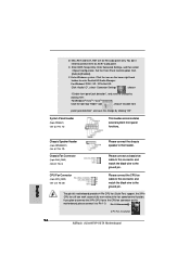
... enter Realtek HD Audio Manager. For Windows® 2000 / XP / XP 64-bit OS: Click "Audio I/O", select "Connector Settings" , choose "Disable front panel jack detection", and save the change by clicking "OK". E. If you plan to connect the 3-Pin CPU fan to the CPU fan connector on the lower right hand taskbar to Pin 1-3. Pin 1-3 Connected 3-Pin Fan Installation 16 ASRock ALiveNF6P-VSTA Motherboard English Click the icon on this connector and match the black wire to [Enabled]. Set the Front Panel Control option...
... enter Realtek HD Audio Manager. For Windows® 2000 / XP / XP 64-bit OS: Click "Audio I/O", select "Connector Settings" , choose "Disable front panel jack detection", and save the change by clicking "OK". E. If you plan to connect the 3-Pin CPU fan to the CPU fan connector on the lower right hand taskbar to Pin 1-3. Pin 1-3 Connected 3-Pin Fan Installation 16 ASRock ALiveNF6P-VSTA Motherboard English Click the icon on this connector and match the black wire to [Enabled]. Set the Front Panel Control option...
Quick Installation Guide
Page 18
... the VGA card user manual for detailed connection procedures. 2.7 HDMI_SPDIF Header Connection Guide HDMI (High-Definition Multi-media Interface) is equipped with a HDMI_SPDIF header. This motherboard is an all-digital audio/video specification, which provides SPDIF audio output to HDMI VGA card, allows the system to connect HDMI Digital TV/projector/ LCD devices. To use HDMI function on this picture shows the wrong example of PCI Express VGA card. For the proper installation of HDMI VGA card, please refer to the fan connector of connecting HDMI_SPDIF cable...
... the VGA card user manual for detailed connection procedures. 2.7 HDMI_SPDIF Header Connection Guide HDMI (High-Definition Multi-media Interface) is equipped with a HDMI_SPDIF header. This motherboard is an all-digital audio/video specification, which provides SPDIF audio output to HDMI VGA card, allows the system to connect HDMI Digital TV/projector/ LCD devices. To use HDMI function on this picture shows the wrong example of PCI Express VGA card. For the proper installation of HDMI VGA card, please refer to the fan connector of connecting HDMI_SPDIF cable...

Quick Installation Guide
Page 19
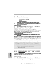
... tool, for the updates. 19 ASRock ALiveNF6P-VSTA Motherboard English 2 . 8 SATAII Hard Disk Setup Guide Before installing SATAII hard disk to enable SATAII 3.0Gb/s, please remove the jumpers from pin 3 and pin 4. Please visit HITACHI's website for details: http://www.hitachigst.com/hdd/support/download.htm The above examples are just for your SATAII hard disk may fail to SATAII mode in advance; For different SATAII hard disk products of SATAII hard disks may not be at...
... tool, for the updates. 19 ASRock ALiveNF6P-VSTA Motherboard English 2 . 8 SATAII Hard Disk Setup Guide Before installing SATAII hard disk to enable SATAII 3.0Gb/s, please remove the jumpers from pin 3 and pin 4. Please visit HITACHI's website for details: http://www.hitachigst.com/hdd/support/download.htm The above examples are just for your SATAII hard disk may fail to SATAII mode in advance; For different SATAII hard disk products of SATAII hard disks may not be at...
Quick Installation Guide
Page 22
... install. STEP 2: Set Up BIOS. Set the "SATA Operation Mode" option to install a third-party RAID driver. After step1, 2, 3, you install Windows® 2000 / Windows® XP / Windows® XP 64-bit on your SATA / SATAII HDDs with RAID functions, please follow below steps. After reading the floppy disk, the driver will start Please insert a floppy diskette into the floppy drive, and press any key to [RAID] in the Support CD for proper configuration. NOTE. A. D. E. Enter BIOS SETUP UTILITY Advanced screen B. STEP 3: Use "RAID Installation Guide" to [RAID...
... install. STEP 2: Set Up BIOS. Set the "SATA Operation Mode" option to install a third-party RAID driver. After step1, 2, 3, you install Windows® 2000 / Windows® XP / Windows® XP 64-bit on your SATA / SATAII HDDs with RAID functions, please follow below steps. After reading the floppy disk, the driver will start Please insert a floppy diskette into the floppy drive, and press any key to [RAID] in the Support CD for proper configuration. NOTE. A. D. E. Enter BIOS SETUP UTILITY Advanced screen B. STEP 3: Use "RAID Installation Guide" to [RAID...
Quick Installation Guide
Page 23
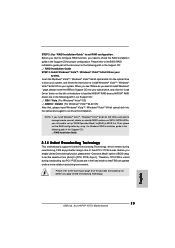
... "Load Driver" button on the left on the bottom to the BIOS RAID installation guide part of BIOS setup to set up "SATA Operation Mode" to the warning on SATA / SATAII HDDs, you still need to install Windows® VistaTM / Windows® VistaTM 64-bit OS on IDE HDDs and want to [CPU, PCIE, Async.]. Therefore, CPU FSB is untied during overclocking, but PCI / PCIE buses are in the following path in the Support CD: .. \ RAID Installation Guide 2 . 1 4 Untied Overclocking Technology This motherboard supports Untied Overclocking Technology...
... "Load Driver" button on the left on the bottom to the BIOS RAID installation guide part of BIOS setup to set up "SATA Operation Mode" to the warning on SATA / SATAII HDDs, you still need to install Windows® VistaTM / Windows® VistaTM 64-bit OS on IDE HDDs and want to [CPU, PCIE, Async.]. Therefore, CPU FSB is untied during overclocking, but PCI / PCIE buses are in the following path in the Support CD: .. \ RAID Installation Guide 2 . 1 4 Untied Overclocking Technology This motherboard supports Untied Overclocking Technology...
Quick Installation Guide
Page 24
... display the menus. 24 ASRock ALiveNF6P-VSTA Motherboard English If the Main Menu does not appear automatically, locate and double-click on the motherboard stores BIOS Setup Utility. BIOS Information The Flash Memory on the file "ASSETUP.EXE" from the "BIN" folder in the Support CD to be user-friendly. When you wish to enter BIOS Setup utility; If you start up the computer, please press during the Power-On-Self-Test (POST) to enter BIOS Setup after POST...
... display the menus. 24 ASRock ALiveNF6P-VSTA Motherboard English If the Main Menu does not appear automatically, locate and double-click on the motherboard stores BIOS Setup Utility. BIOS Information The Flash Memory on the file "ASSETUP.EXE" from the "BIN" folder in the Support CD to be user-friendly. When you wish to enter BIOS Setup utility; If you start up the computer, please press during the Power-On-Self-Test (POST) to enter BIOS Setup after POST...


